Week3 : Computer-Controlled Cutting
This week has three assignments:
1.Make lasercutter test part(s), varying cutting settings and slot dimensions.
2.Design, make, and document a parametric press-fit construction kit, accounting for the lasercutter kerf, which can be assembled in multiple ways.
3.Cut something on the vinylcutter
I used 2D design software which is CorelDraw to draw the patterns, and 3D design tool which is FreeCAD to do the parametric design. The cutting material is the remaining Acrylic which our lab used before.
1.Make lasercutter test part(s), varying cutting settings and slot dimensions.
In this section, the lasercuter I used is "Laser System DC-13090-N", made by 3AXLE Technology Company. the power of this lasercutter is 130W, so it is easy to cut anything besides metal. The thickness of the remaining acrylic I used was 3mm, so I drawed 22 slots which evenly distributed between 2.90mm to 3.20mm.
At the first, the cutting power I setted was 80% of 130W, and the speed of the cutter's movment was 20 mm/s, But it could not burn through well. So I reduced the cutter's movment to 15 mm/s, it could burn through well finally.
After finishing cutting, I obtained two the same slots tools. Than I tried to fit these two slots tools, I found that these two slots tools could fit well with the width 2.94mm of the slot. That means there has margin tolerance about 0.06mm with this lasercutter. So I follow the margin tolerance to design the following press-fit construction kit.
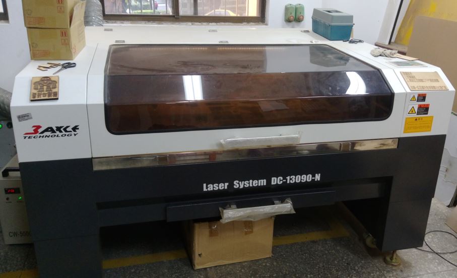
figure 1: "Laser System DC-13090-N", made by 3AXLE Technology Company.
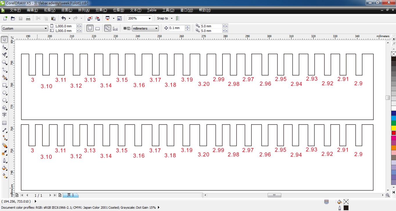
figure 2: Drawing 22 slots which evenly distributed between 2.90mm to 3.20mm on CorelDraw.
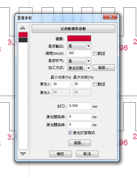
figure 3: Setting the speed of the cutter's movment and the cutting power.
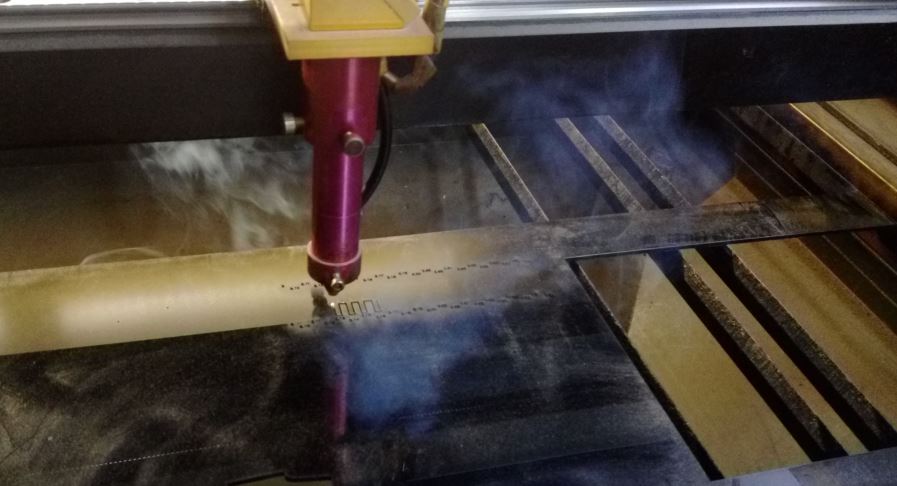
figure 4: Cutting the slots tools.
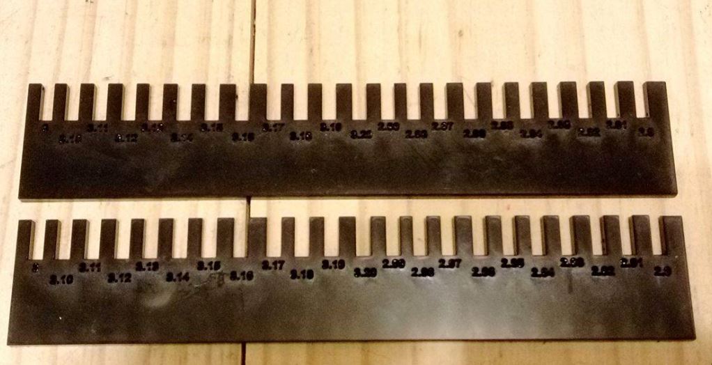
figure 5: Obtaining two the same slots tools.
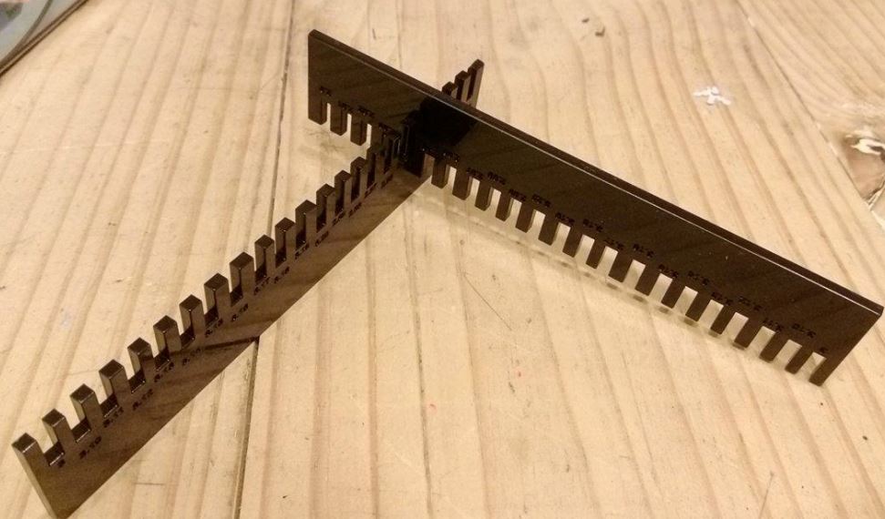
figure 6: These two slots tools could fit well with the width 2.94mm of the slot.
2.Design, make, and document a parametric press-fit construction kit, accounting for the lasercutter kerf, which can be assembled in multiple ways.
Although I used Rhino and Grasshopper to do the parametric design last week. I tried to use another modeling tool which was FreeCAD to realize parametric design this week.
First, I drawed a pentagon with had a 3X3mm square on the middle of each side. Than I cloned these five squares.
Second, I builded a Spreadsheet which had two parameters in it, height and length. Then I type "Spreadsheet.height" and "Spreadsheet.length" in the "Height" and "Length" fields respectively on the "Property" of the original square.
Third, I used the feature "BooleanDifference" to obtain the shape of the press-fit construction kit. Then I used another feature "Array" to obtain severial shapes. And I could easily change the height and length of the lasercutter kerf with all the shapes at the same time by only changing the values in the Spreadsheet.
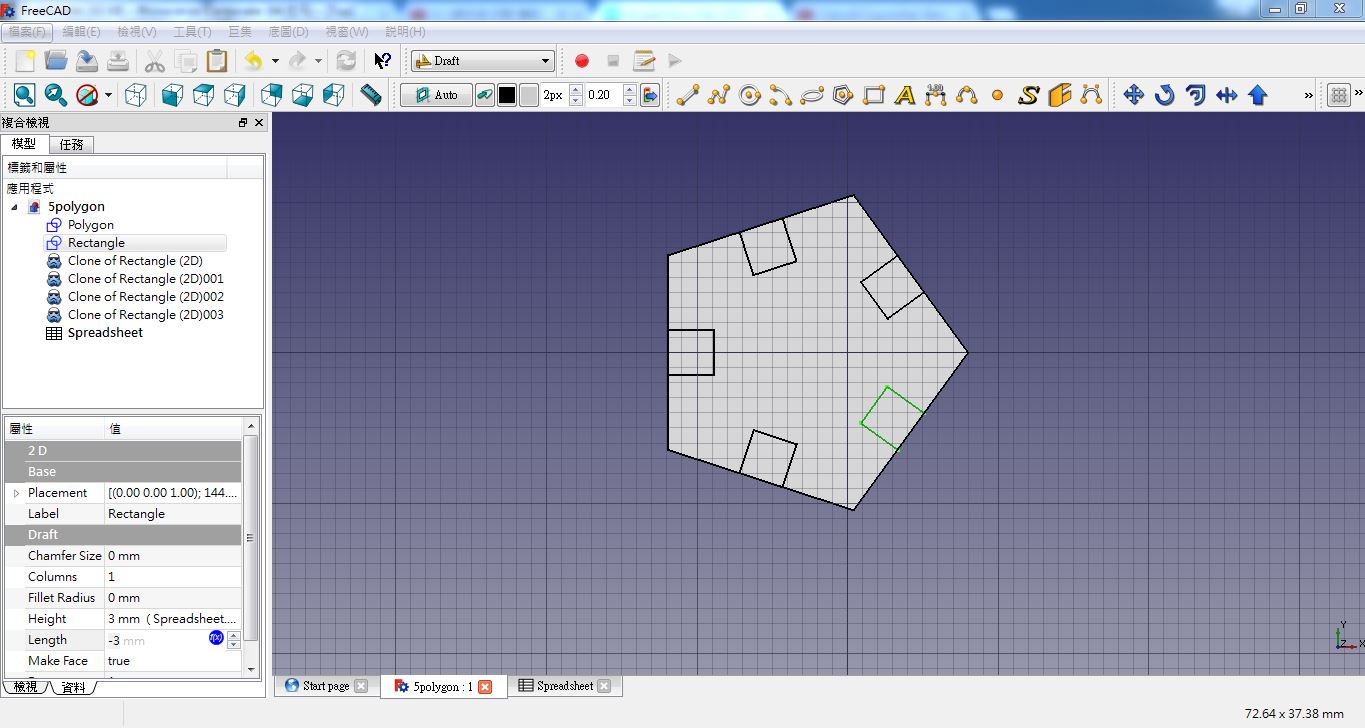
figure 7: Drawing a pentagon with had a 3X3mm square on the middle of each side, and
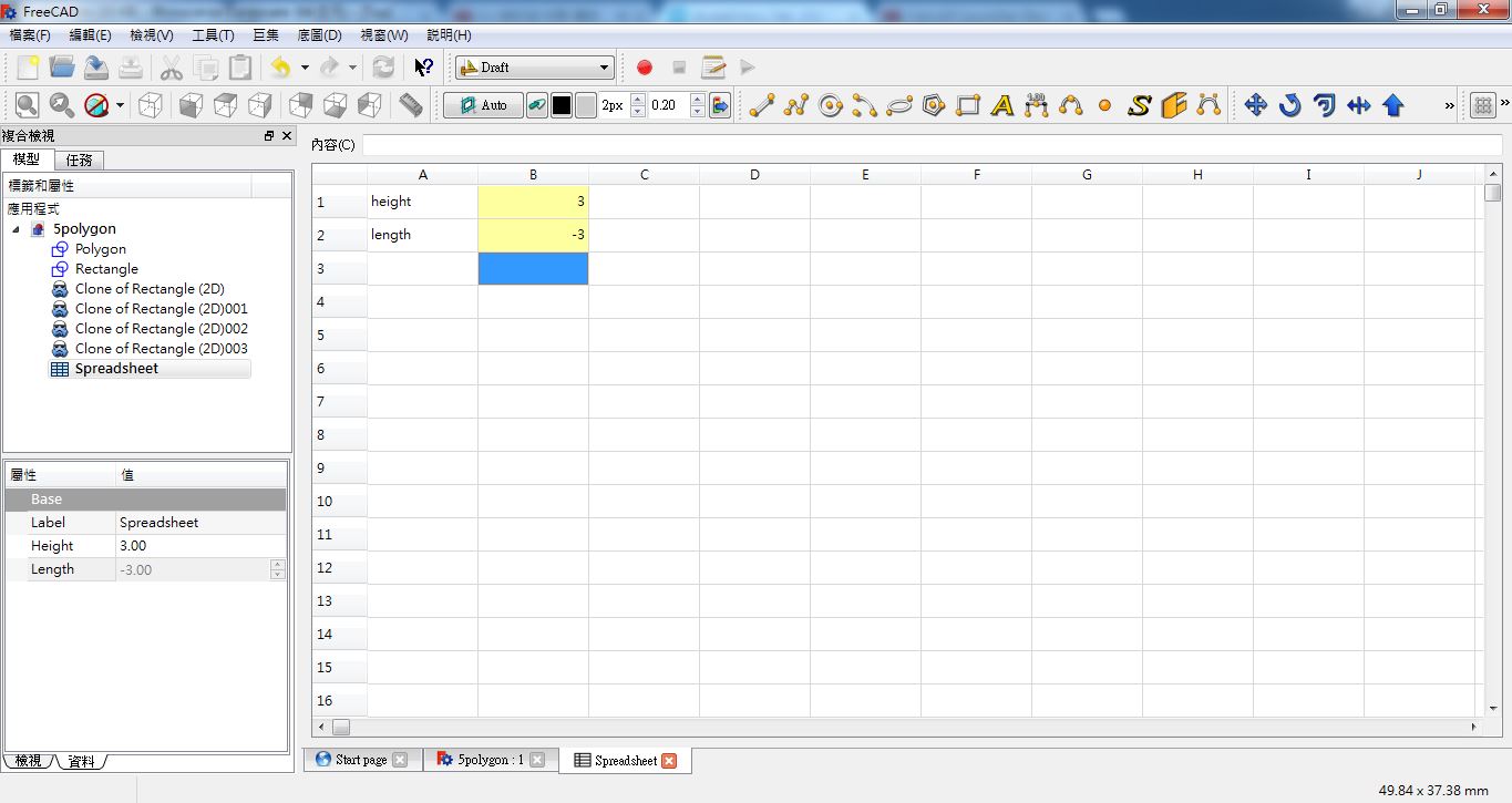
figure 8: Building a Spreadsheet which had two parameters in it, height and length.
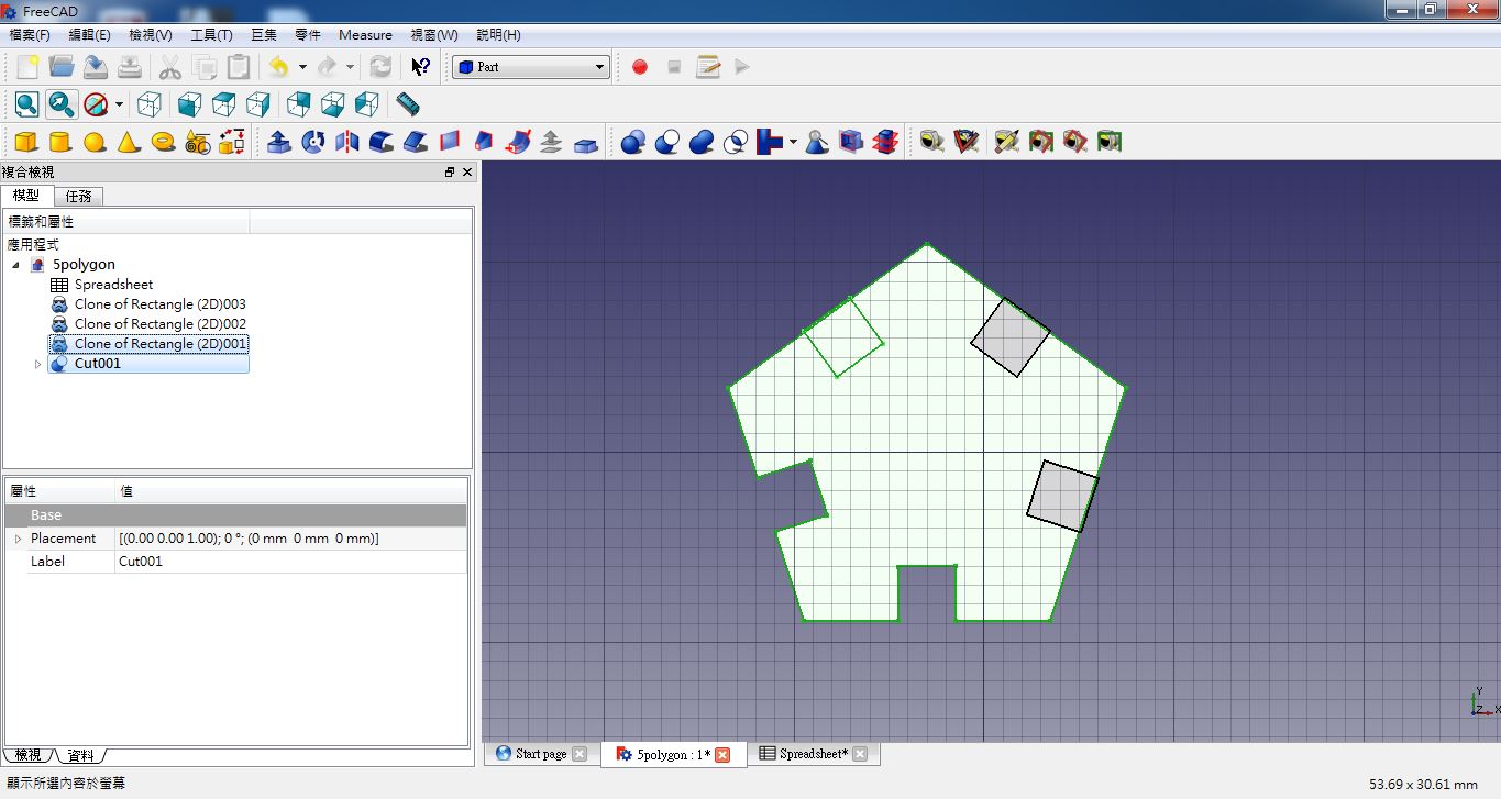
figure 9: Using the feature "BooleanDifference" to obtain the shape of the press-fit construction kit.
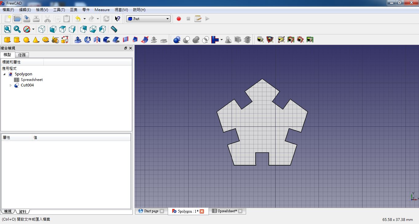
figure 10: The shape of the press-fit construction kit.
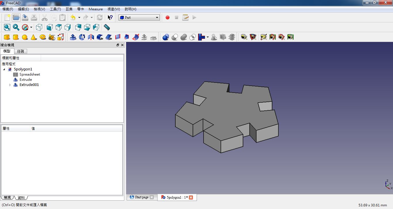
figure 11: The 3D shape of the press-fit construction kit.
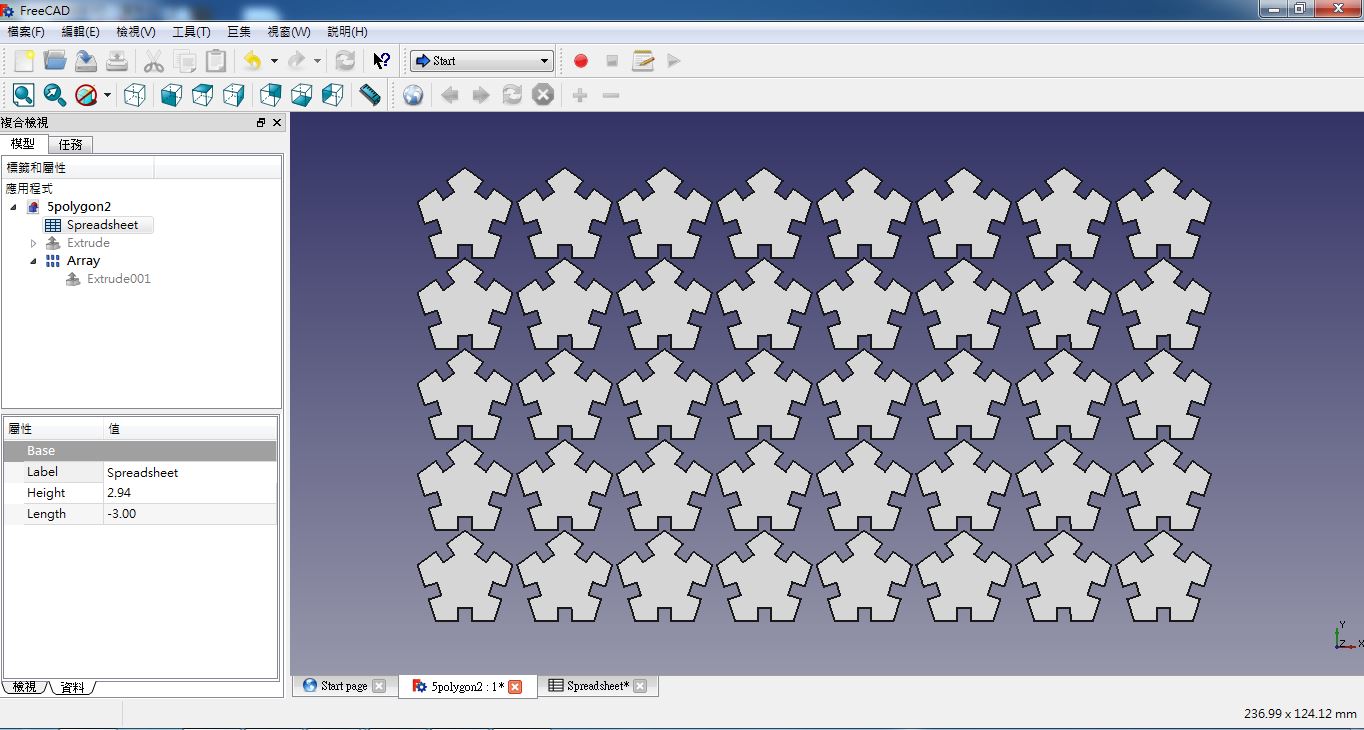
figure 12: Using another feature "Array" to obtain severial shapes.
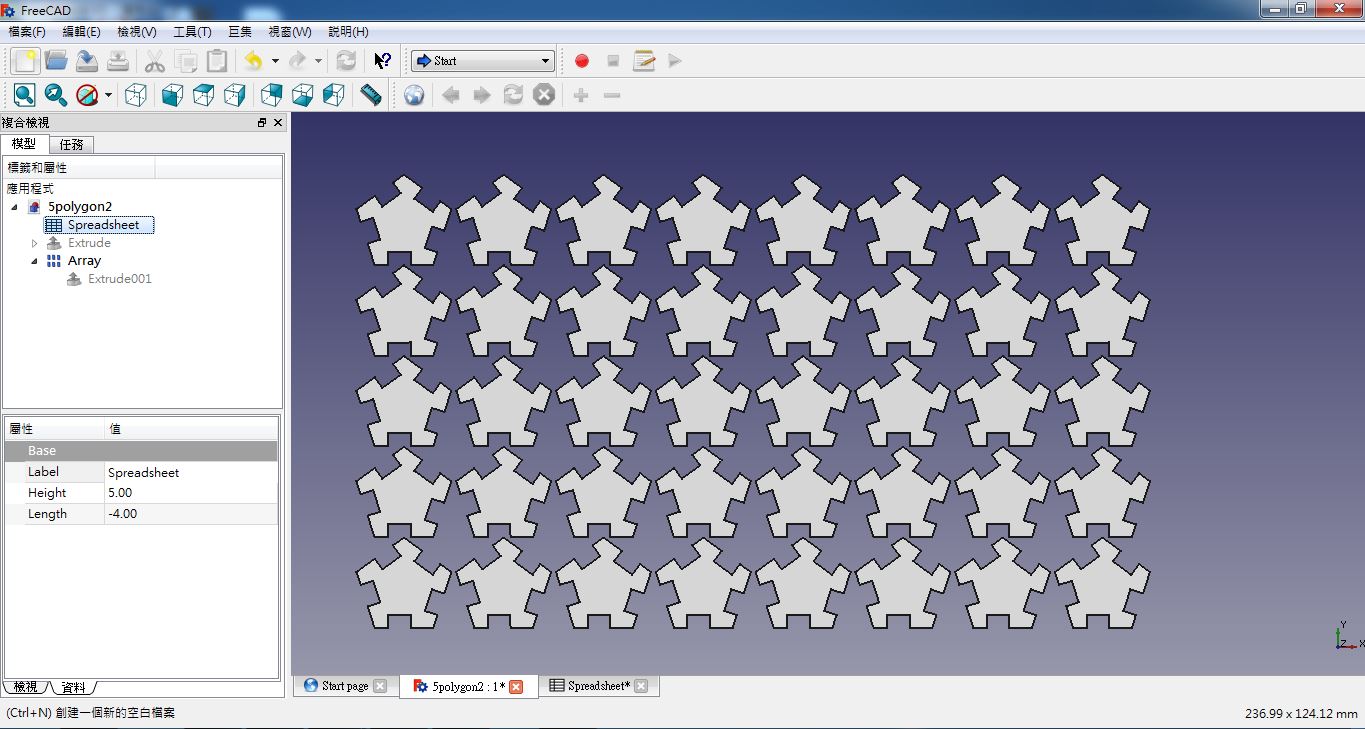
figure 13: I could easily change the height and length of the lasercutter kerf with all the shapes at the same time by only changing the values in the Spreadsheet.
But I cuted these press-fit construction kits with another lasercutter which located on Fablab taipei. So I needed to find the margin tolerance of this lasercutter, and this time I changed the remaining material to Middi board. After finishing the slots tool, I finded the margin tolerance was alse 0.06mm. Then I moved on the following cutting work.
After cutting, I obtained several press-fit construction kits. So I assembled these kits to a beast I imagined.
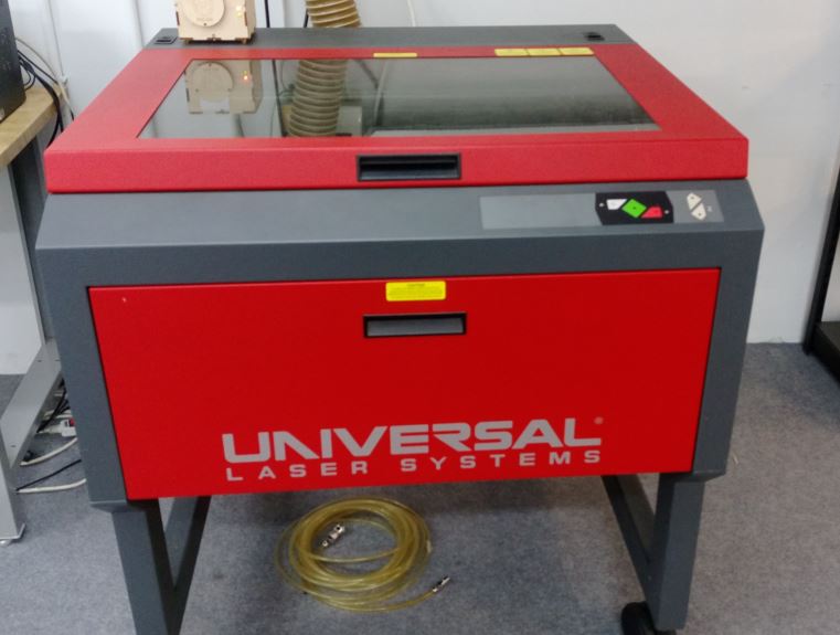
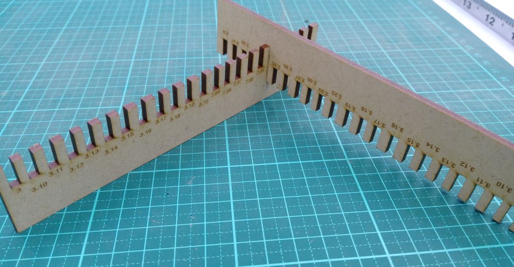
figure 14: The lasercutter in Fablab Taipei and the new slots toll.
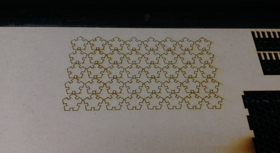
figure 15: After cutting, I obtained several press-fit construction kits.
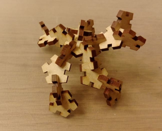
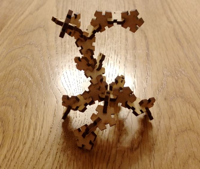
figure 16: I assembled these kits to a beast I imagined.
3.Cut something on the vinylcutter
I inputed the picture to the CorelDraw, then draw the contour of the picture. I could easily launch the "Cutting Master 3" with CorelDraw operating environment. I could easily communicate with vinylcutter via Cutting Master 3.
After Cutting the patterns, I stickied these patterns to my notebook. It is a wonerful experience.
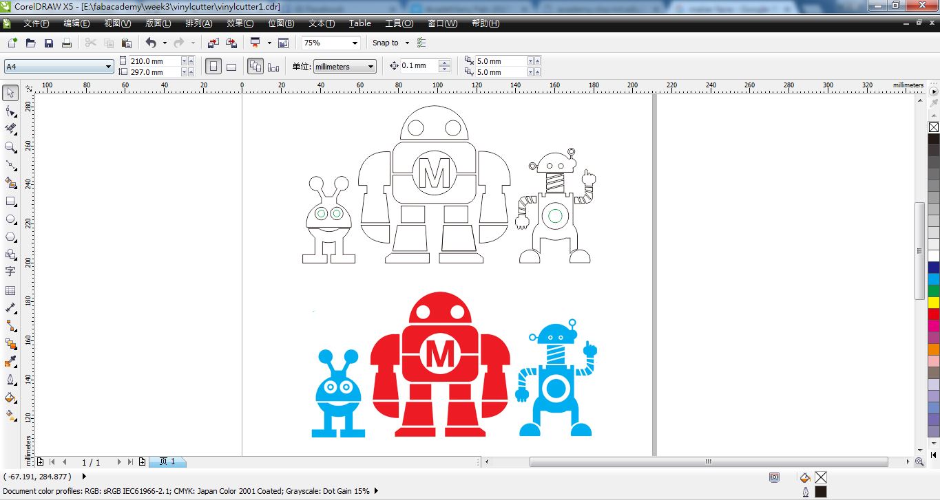
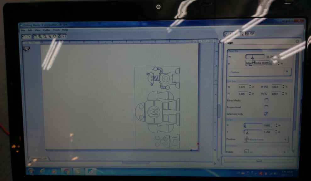
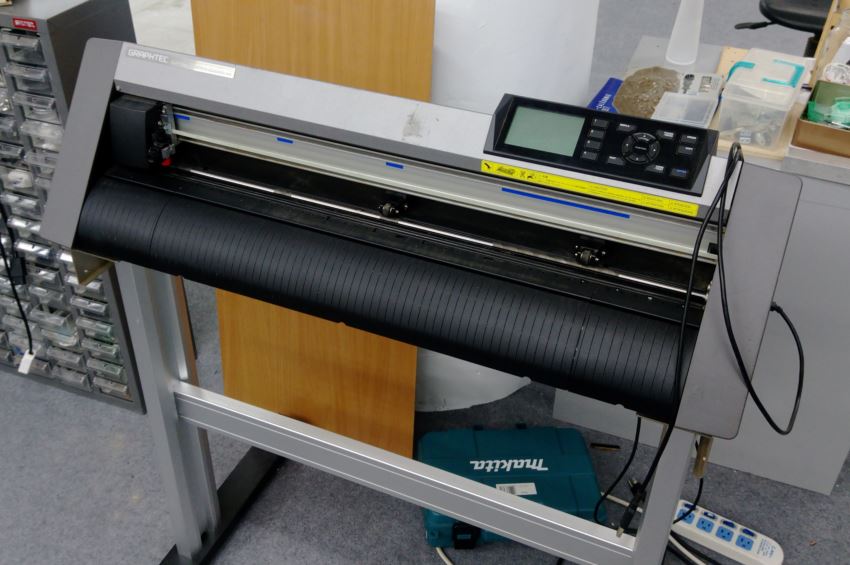
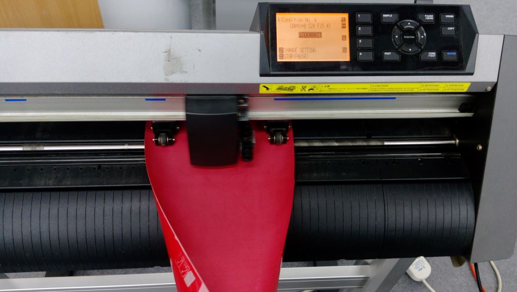
figure 17: Using CorelDraw to draw the contour of the picture, and cutting it via vinycutter.
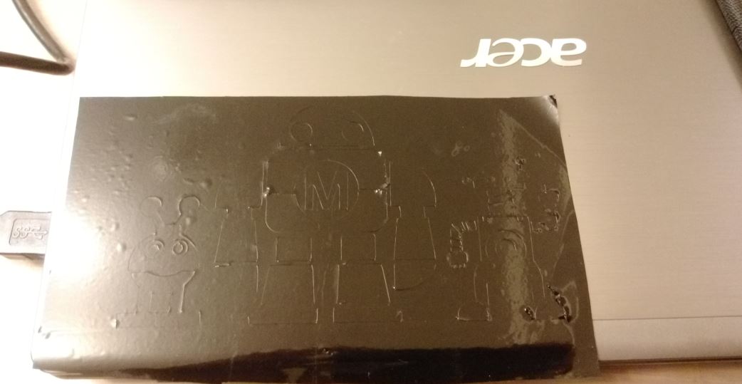
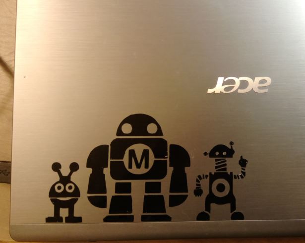
figure 18: Stickied these patterns to my notebook.
I tried another material which was PU(Polyurethane) film to cut the same pattern, then coating the pattern to a T-shirt by using heat transfer printer. I printed the pattern to a moisture wicking sweater, so I set the heatting time to 30 seconds and temperature to 185 degrees. Then I got a handmade T-shirt.
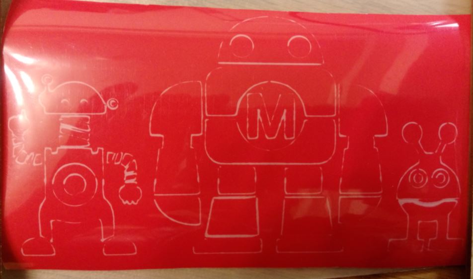
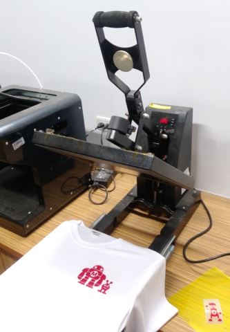
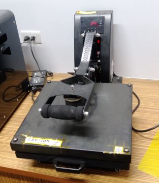
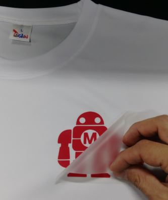
figure 19: Using heat transfer printer to print the pattern to a moisture wicking sweater.

figure 20: I got a handmade T-shirt.
Source file
1.Draw slots tools with CorelDraw.2.Output DXF type of slots tools.
3.Parametric Design with FreeCAD.
4.Output DXF type of press-fit construction kit.
5.Output DXF type of press-fit construction kits(array).
6.Contour of the robot with CorelDraw.
7.Output DXF type of Contour with CorelDraw for vinycutter.
8.Output SVG type of Contour with CorelDraw for vinycutter.