Exercise 05 3D Scanning and Printing
Assignment Requirements
- Test the design rules for your printer(s) (group project)
- Design and 3D print an object (small, few cm) that could not be made subtractively
- 3D scan an object (and optionally print it)
Introduction
Additive Manufacturing is a term to describe set of technologies that create 3D objects by adding layer-upon-layer of material. 3D printing is addictive manufacturing. On the other hand, subtractive manufacturing is a process by which 3D objects are constructed by successively cutting material away from a solid block of material. Subtractive manufacturing can be done by manually cutting the material but is most typically done with a CNC Machine.
The only 3D Printing Technology that we going to cover
- Filament-based 3D Printing (Fused Deposition Modeling): Home printers typically work with plastic filament. The technology behind this is often referred to as “Fused Filament Fabrication” (FFF). In our 3D printing factory, we have more professional, industrial-grade machines: our filament printers use a technology called “Fused Deposition Modeling” (FDM). In an FDM printer, a long plastic filament is fed by a spool to a nozzle where the material is liquefied and ‘drawn’ on the platform, where it immediately hardens again. The nozzle moves to place the material in the correct location to build your model up layer by layer. When a layer is drawn, the platform lowers by one layer thickness so the printer can start with the next layer.
Stress-testing the 3D Printer
Test The Design Rules of In-house 3D-Printer(s)
This is a group project to analyse and study the limitation of in-house 3D-Printers.
Ultimaker 2+
Fablab@SP has mostly Ultimaker 2+. Naturally our evaluation study was started with Ultimaker 2+.Ultimaker 2+ use PLA filement as the raw material. The software use is call Cura; and the current version of Cura can be found. We started with all the default setting for our simple cube evaluation.
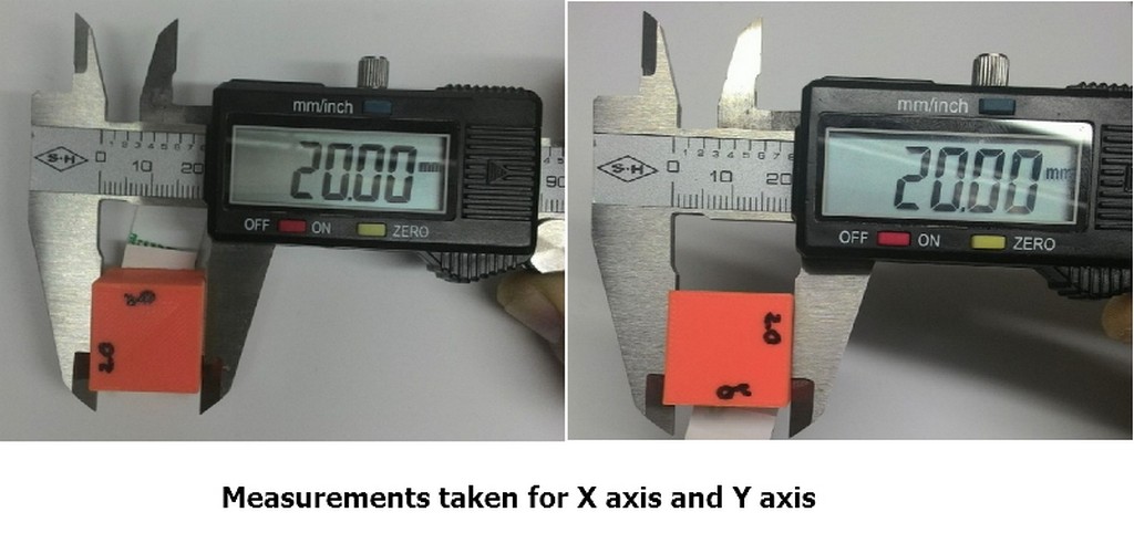
Our group started the Ultimaker 2+ 3D printer evalutaion with test print of a self CAD cube of size 20mm x 20mm x 20mm, and took the measurements for x axis, y axis and z axis.
The measurements are shown:
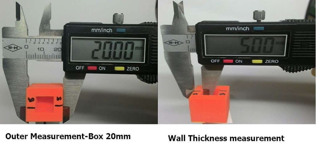
Follwoing that we further evaluated the capability of Ultimaker 2+ to print out of a box of 20mm volume 10mm inner cut out and measured the outer wall thickness. Wall thickness accurately measured to be 5mm thick.
The measurements are shown:
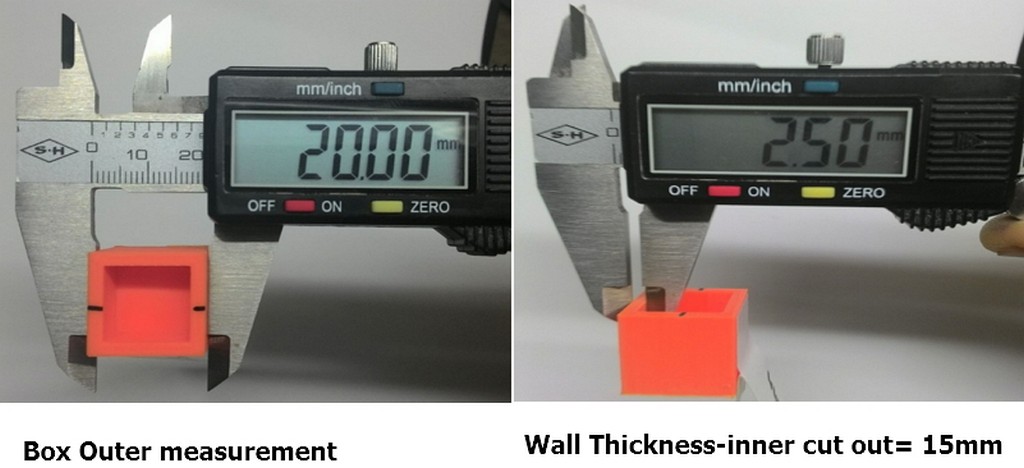
Similarly we also repeated with same volume box but with inner cut out of 15mm and measured the outer wall thickness. Wall thickness accurately measured to be 2.5mm thick.
The measurements are shown:
From these simple cube/box printout evaluation we can conclude that the Ultimaker 2+ is able to print out the exact same size of model as design with default machine settings.
Next up, we downloaded our two test models from Thinginverse for further evaluation of Ultimaker 2+ with its default print setting.
 |
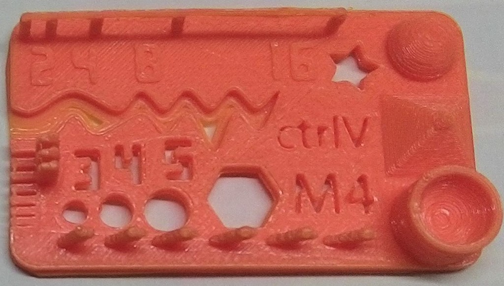 |
| Ultimaker 2+ is capable to print out models with overhang nicely without support up to 60 degrees gradien. Anything greater than 60 degree the slop started to have surface deformation which can be felt by touch. | The printer printed 13 out of 14 features successfully. With some of the thinner wall not appearing. This may be due to moisture within the filaments and machine wear and tear. |
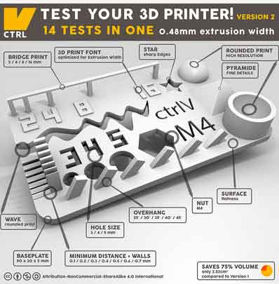
From the picture we knew that the 14-in-1 tests supposedly to cover follwing evaluations:
- Size: the object is 2 x 50 x 30mm (baseplate)
- Hole size: 3 holes (3/4/5mm)
- Nut size: M4 Nut should fit perfectly
- Fine details: pyramide, cone, all numbers
- Rounded print: wave, half sphere
- Minimum distance & walls: 0.1/0.2/0.3/0.4/0.5/0.6/0.7mm
- Overhang: 25°/30°/35°/40°/45°
- Bridge print: 2/4/8/16/mm
- Surface: all the flat parts
Our findings and observation with Ultimaker 2+ are as follows:
- Size: cleared (baseplate)
- Hole size: Cleared
- Nut size: Cleared
- Fine details: pyramide, cone, all numbers - Cleared
- Rounded print: wave, half sphere - Cleared
- Minimum distance & walls: 0.1/0.2/0.3/0.4/0.5/0.6/0.7mm - Failed to print walls which are less than 0.5mm. Minimum distance is about 0.5mm.
- Overhang: 25°/30°/35°/40°/45° - Cleared
- Bridge print: 2/4/8/16/mm - Cleared.
- Surface: all the flat parts - Cleared
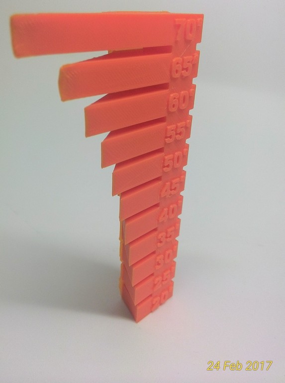
With this findings, our group concurrently printed the overhang test model as an extension from the overhang test in 14-in-1 tests model; and found that Ultimaker 2+ was able to print without any slop deformation at and angle of 60 degree. Starting from 65 degree the slop surface output started to fail.
Our group then proceed to evaluate the quality to speed of Ultimaker 2+. The following are the recorded findings:
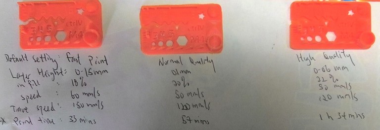
| Default Setting: | Fast Print | Normal Quality | High Quality |
|---|---|---|---|
| Layer Height: | 0.15mm | 0.1mm | 0.06mm |
| Infill: | 18% | 20% | 22% |
| speed: | 60mm/s | 50mm/s | 50mm/s |
| travel speed: | 150mm/s | 120mm/s | 120mm/s |
| print time: | 37mins | 57mins | 1hr34mins |
Cubicon 3D Printer
My classmate, Louis did a similar test on Cubicon 3DP-110F, a 3D printer from Korea, and below is his result.
According to Louis, Cubicon printers is using their own unique slicer software. Within the slicer, there are advance settings that we can altered to evaluate the printer capabilities. In this exercise, our group study with 2 different settings in separate prints for the evaluation.
Cubicon built in tiny nozzle supposedly is able to yield precisionly with output of very high resolution. With well better control work plate temperature within the enclosure, our group would expect that print outs are difference in term of output timing and the ability to print certain walls.
As shown in the screen shots below:
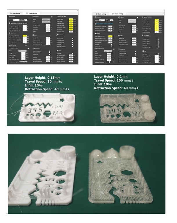
To our suprise, at resolution of 0.15mm, Cubicon failed to print the thin walls of between 0.4-0.1 mm. At a higher resolution setting, Cubicon failed print print the thin walls and the outputs one other area appears to be more "stringier" than when the resoultion was set to 0.2mm.
Louis suspected that it might be because of the limitation slicer software, it may not be able to slice the the thin walls.
.Then I referred to one of our senior - Mark's report that mentioned something like cubicon specification stated that the maximun resolution is of 20 micron. Which meant that the machine might not be performing at it's optimum resolution as specify in the machine specification.Perhaps, it is time to call for servicing.
Design and 3D print an object (small, few cm) that could not be made subtractively
Since I have learnt how to CAD from one of the Fusion 360 tutorial which thought me to CAD a lamp shade. I created my own lamp shade; and scaled down the model to 5cmx5cmx5cm for this week assignment. A simplify steps in snapshot was documented as follow:
The original lampshade file created from Fusion; can be downloaded here.
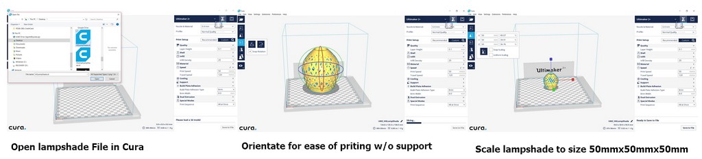
From the printer test on Ultimaker 2+, I decided to do a test print using the default fast printing parameters as shown in the table below:
| Default Setting: | Fast Print |
|---|---|
| Layer Height: | 0.15mm |
| Infill: | 18% |
| speed: | 60mm/s |
| travel speed: | 150mm/s |
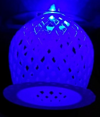
The 3D printed miniature lampshade is as shown:
3D scan an object (and optionally print it)
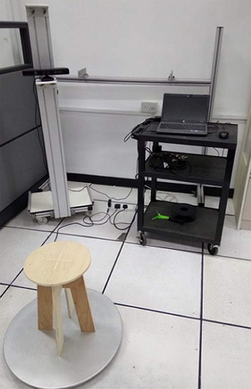
Kinect Pro 3D Scanner
The very first scanner that I played with was non other than the OpenKinect being setup in Fablab@SP. My classmate Louis had help to scan me as the object, where I was seated on a rotary chair revolved around the "Skanect" 3D Scanner as shown:
The operation steps involved roughly are as follows:
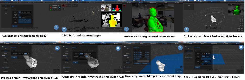
The STL file produced can be downloaded from:
NextEngine UltraHD Desktop 3D Scanner
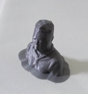
I also went through the processes in NextEngine 3D Scanner UltraHD to generate the following HG-Hulk.STL File which can be downloaded from:
A simplified steps of using were as follow:
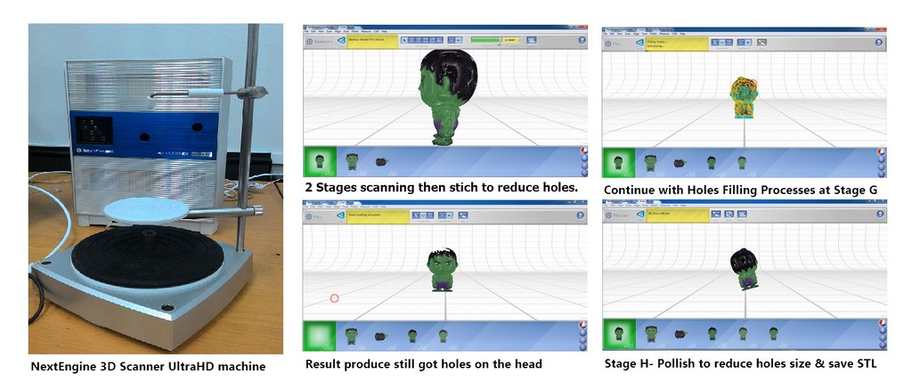
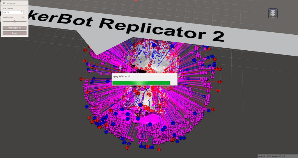
From the huge scanned file size of 12.9MB, I can roughly tell that the scanned figurine is full of holes here and there. True enough when loaded into Cura. I can see that the area which were indicated as red are not watertight.
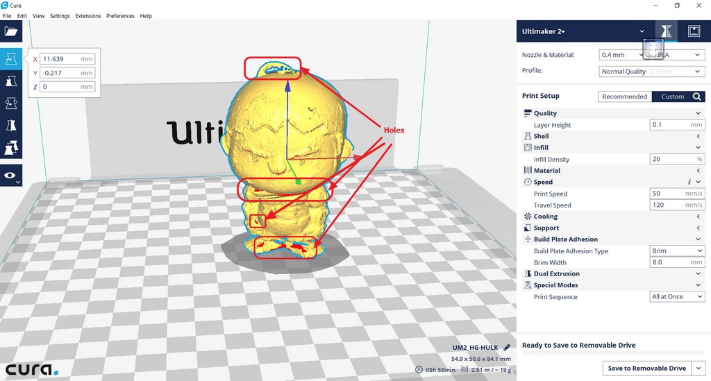
Immediately, I am thinking of secondary processing using Autodesk meskmixer is rquired. I am not familiar with this software, as normally we would just refer our students back to seek their lecturer assistance. So it is a entirely new software to me.
To start with, I imported the 3D scanned STL file into Autodesk Meshmixer software and start to orientate the object to be place on the workspace, while get myself familiar with the software.
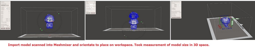
With this model that are full of holes/ not watertight the amount of work to be done is massive and my learning curve would be very steep. Next I tried using
Autodesk 123D catch free 3D scanning software
In order to be able to digitize an object in 3D, the object must be able to reflect light. The object cannot be too shiny or reflective either. A mirrored surface, polished metal or crystal cannot be digitized. Reflections and refractions of the light confuses the reading of the geometry. When the volume to be scanned is extremely thin, the scanner can have difficulty determining the front side from the back side. Other tips and tutorials can be found below:
- 123D Catch Photo Tips
- It’s Easy as 123D Catch
- 123D Catch web app Tutorials
- Autodesk Meshmixer 101 Tutorials
I have been using my phone camera in the normal automode and attempted numeruos times without success for the same Hulk model used in the NextEngine 3D scanner exercise. Various newspaper were being used as base, numerous numbers of photo taken at each attempt; but 123D catch were not able to process the pictures snapshots over the cloud.
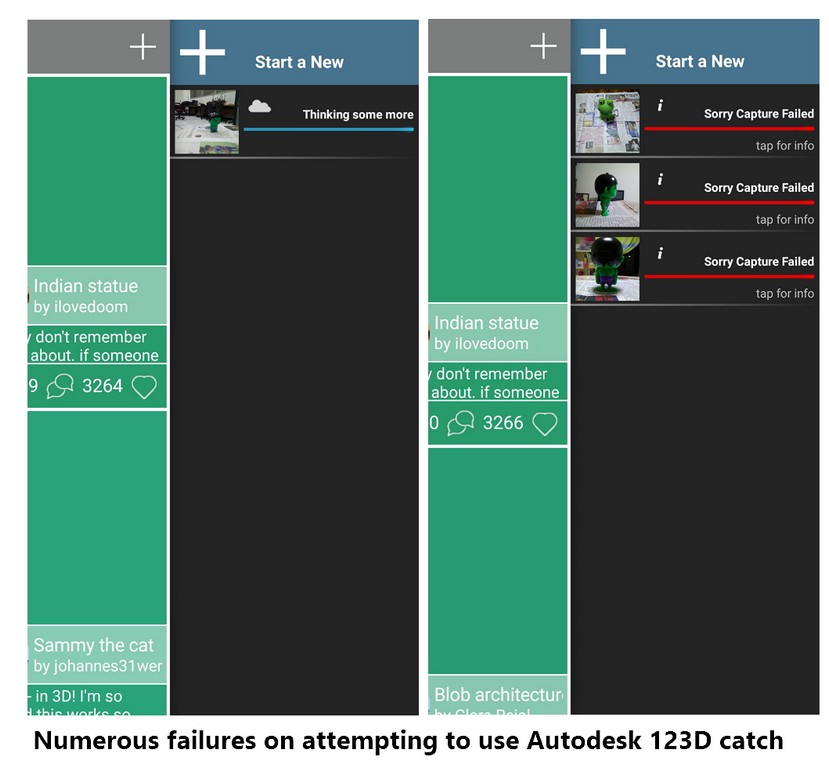
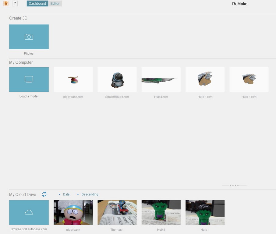
At the Autodesk 123D download page, there is a PC download and brought me to download and tried using Autodesk remake on my laptop for the same HULK model. Similarly the 3D model creation was without success. This make me in doubt of my phone camera, lighting, and surface finishing my kid's Hulk figurine.
I guess the following screen capture does explained a bit of my numeruos failure attempts.
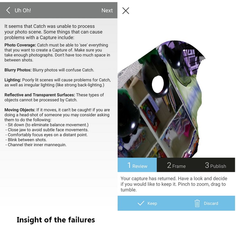
Look like the background had completely engulfed the main character - Hulk figurine. All digital photo nowadays supposedly to be of super high resolution. The background taken seem to be equally as high resolution as the little figurine of size 50mmx50mmx78mm. What I am trying to deduce is the background blury of super high resolution had became too noisy and interfered with the processing of the main object thus caused the failures.
Important References
- Additive Manufacturing vs Subtractive Manufacturing
- Types of 3D printers or 3D printing technologies overview
- Designer Creates an All-in-One Solution for Testing & Calibrating Your 3D Printer
- Test your 3D printer! v2
- The Most Important 3D Printing Technologies & Materials You Need to Know
- How to Choose the Perfect File Resolution When Turning Your 3D Model into a 3D Print
- 3D Printing Tips & Tricks – How to 3D Model A Great 3D Print
- How to Design and 3D Print Chainmail Patterns and Interlocking Parts
- 5 Mistakes to Avoid When Designing a 3D Model for 3D Printing
- 3D Design Rules
- Things to keep in mind when designing for 3D Printing
- 3D Design For 3D Printing
- Design tips
- PLA vs ABS | What's the Difference for 3D Printing?
- Make: Design for 3D Printing by Samuel N. Bernier, Bertier Luyt, Tatiana Reinhard
- Download an STL of your 123D Catch project