~ Interface and Application Programming.
~ post date: 2017.5.23, recent update: 2017.6.2
I have a grasshopper script for transcoding G-code for the dishuBot and some lingering disabilities. I think it would be interesting to explore the possibility of using the Firefly grasshopper plugin to control the motors and pump in place of GRBL. Then, I will remove one additional step in the process of sending instruction to the robot and gain control. For instance, I always intended to separate the control of the two Y-axis movement motors so the robot would be free to draw outside of a straight line. Currently, 4-axis movement is an early stage branch of GRBL.
Project files
Processing : coming around.
In graduate school, I had the fortune of learning a bit of Processing, which I used in an interactive design project called FIZZLE in Hollywood. That was then, this is now. Now is a time when I have forgotten everything. Until today. From the processing website:
"Processing is a simple programming environment that was created to make it easier to develop visually oriented applications with an emphasis on animation and providing users with instant feedback through interaction. The developers wanted a means to “sketch” ideas in code. As its capabilities have expanded over the past decade, Processing has come to be used for more advanced production-level work in addition to its sketching role. Originally built as a domain-specific extension to Java targeted towards artists and designers, Processing has evolved into a full-blown design and prototyping tool used for large-scale installation work, motion graphics, and complex data visualization."
First thing, it is a good idea to download Processing.
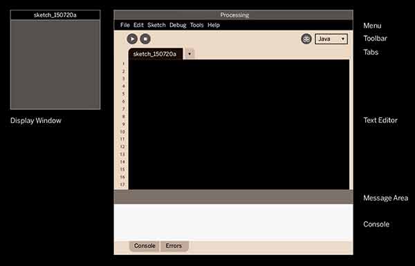
I started with the Getting Started page on the Processing website. You can do that too. I do not know if it is the clear similarities between the Processing Development Environment (PDE) and Arduino IDE or a flood of old memories returning, but this feels very familiar. Like an old blanket. In this sketch, void setup runs once and void draw loops infinitely.
Here is a nice graphic from the website explaning the interface.
After a few minutes of following through the tutorials linked above and below, I decided to just jump in. Enough with the tutorials. Tutorials have their place, but how many different ways do I really need to draw a circle right now? I want to get this connected with my boards!
I found some FabAcademy geared Processing example sketches here. I decided I would start trying to make an animated graphic that reads my phototransistor. I thought that would be easy. Little did I know...
I edited a previous Arduino sketch for greater simplicity. This sends data from the phototransistor to serial for interacting with Processing.
// Using an ATTiny44
// The most basic reading of the phototransistor output to serial
#include <SoftwareSerial.h>
SoftwareSerial mySerial = SoftwareSerial (0,1);    // RX PA1 12, TX PA0 13

// Pin Configurations
const int sensorPin = A2;  // PA2
const int LED = A7;        // PA7
int sensorValue = 0;       // variable to store the value coming from the sensor
//int outputValue = 0;        // variable to store the PWM


void setup() {
  // declare the LED as an OUTPUT:
  pinMode(LED, OUTPUT);
  mySerial.begin(19200);   // I set this to 19200 and arduino monitor to 2400
  mySerial.println("Start.");
}

void loop() {                   // read the value from the sensor every 50 ms
  sensorValue = analogRead(sensorPin);
  mySerial.println(sensorValue);  // print reading to Serial
  //outputValue = map(sensorValue, 0, 1023, 100, 0);  //0 is dark, 100 is bright
  //mySerial.println(outputValue);  // print converted reading to Serial
  //digitalWrite(LED, HIGH);      // Blink LED for visualizing sensor timing
  delay(50);    // calibrate for stability in readings
  //digitalWrite(LED, LOW);
  //delay(50);
}
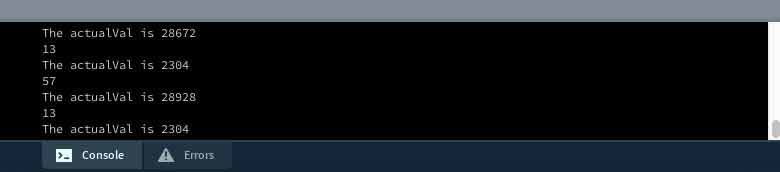
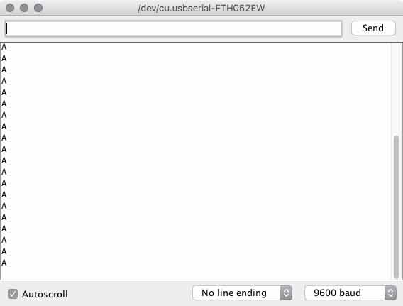
First problem, the Processing serial monitor was incompatible with my board. I was getting erratic readings, irregardless of anything, ie, disconnecting the phototransistor from my board. Something like this:
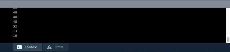
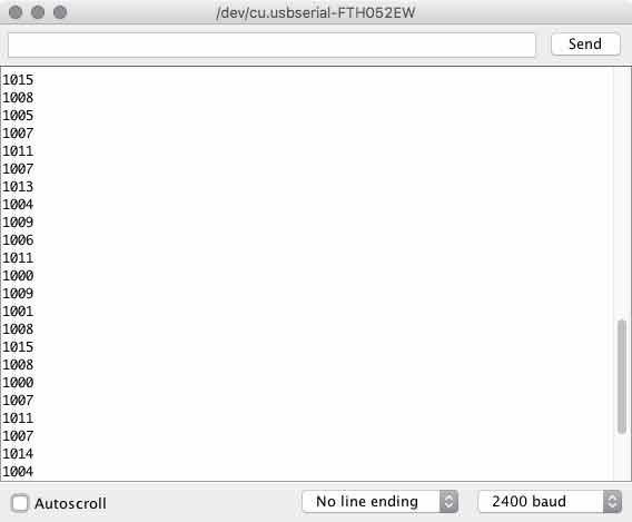
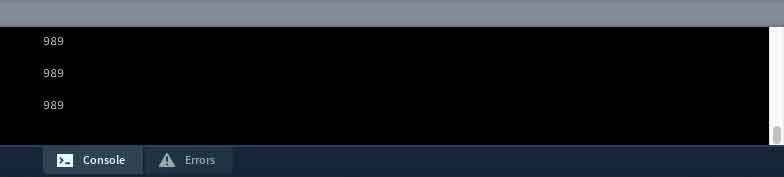
When it should have been this:
Immediately, my mind went back to the timing problems I have had over and over and over again with these ATtiny 44 boards. What am I missing here? I searched around, rolling it back to the start and I found I never used Burn Bootloader. All this time.
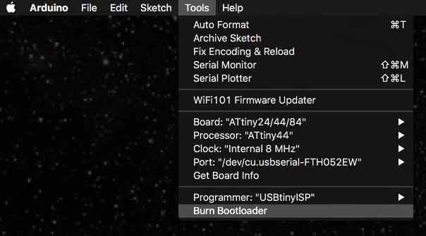
After doing that step, the timing and serial BAUD rate issues melted into distant memories of resilient night terrors. One thing though, the external clock Bootloaders are not working. I will come back to this another day. I think, the resonator is a tough piece to solder, I have already decided to increase the pad lengths next time I use it. I will test this on other boards I have with similar setups and diagnose after that. For now, I am using the 8mHz internal clock.
Still using an example code from the bottom of this page which is a processing conversion of Neil Gershenfeld's python phototransistor reading script, my processing readings did not match the Arduino serial readings.
I stripped the sketch down to its most essential elements for transimitting information from serial and still did not have parity with Arduino.
import processing.serial.*;

Serial myPort;  // Create object from Serial class
int val;      // Data received from the serial port

void setup()
{
  size(200, 200);
  // I checked the port list in the Arduino menu, first Bluetooth... then FTDI
  String portName = Serial.list()[1];
  myPort = new Serial(this, portName, 9600);  // I set code to 19200 and monitor to 2400
}

void draw()
{
  if (myPort.available() > 0) {    // If data is available
    val = myPort.read();           // read it and store it in val
    println(val);
  }
}
Finally, on the Sparkfun tutorial data is read from serial and stored in a String, instead of an int.
import processing.serial.*;

Serial myPort;  // create an object from Serial class
String val;      // data received from the serial port

void setup() {
  String portName = Serial.list()[1];
  myPort = new Serial(this, portName, 9600);
}

void draw() {
 if ( myPort.available() > 0) {
  val = myPort.readStringUntil('\n');
 }
 println(val);
}
Boss.
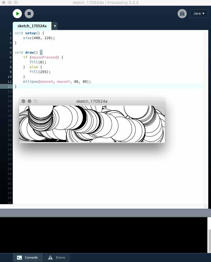
A string is a sequence of characters though. This may be a problem. Now I am having some fun with tutorials, so I continue with the next communicating from Processing through my board, to Arduino and back to the board. First the processing sketch. When I perform a mouse click within the processing menue, a 1 is written via serial.
import processing.serial.*;

Serial myPort;  // create an object from Serial class
String val;      // data received from the serial port

void setup() {
  size(200,200);  // draw a window 200x200 pixels
  String portName = Serial.list()[1];  //adjust for your FTDI cable
  myPort = new Serial(this, portName, 9600);  //match arduino
}

void draw() {
  if (mousePressed == true) {
    myPort.write('1');
    println("1");
  } else {
    myPort.write('0');
  }
  //if ( myPort.available() > 0) {
  //val = myPort.readStringUntil('\n');
 //}
 println(val);
}
Arduino recognizes that and illuminates the LED. And it works.
#include <SoftwareSerial.h>
SoftwareSerial mySerial = SoftwareSerial (0,1);    // RX PA1 12, TX PA0 13

char val;  // Data from serial
int ledPin = A7;

void setup() {
  pinMode(ledPin, OUTPUT);
  mySerial.begin(9600);
}

void loop() {
   if (mySerial.available())
   { // If data is available to read,
     val = mySerial.read(); // read it and store it in val
   }
   if (val == '1')
   { // If 1 was received
     digitalWrite(ledPin, HIGH); // turn the LED on
   } else {
     digitalWrite(ledPin, LOW); // otherwise turn it off
   }
   delay(10); // Wait 10 milliseconds for next reading
}
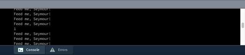
I want to communicate both ways. Apparently, this is called a handshake. Again, following the guiding hand of the tutorial. The Arduino adds a boolean function for controlling the LED and setups an additional loop to confirm communication with Processing through the board. When there is no communication from Processing, it asks for some.
#include <SoftwareSerial.h>
SoftwareSerial mySerial = SoftwareSerial (0,1);    // RX PA1 12, TX PA0 13

char val;  // Data from serial
int ledPin = A7;  //ATtiny44
boolean ledState = LOW; //toggle the LED

void setup() {
  pinMode(ledPin, OUTPUT);
  mySerial.begin(9600);
  establishContact();  // send a byte to establish contact until receiver responds
}

void loop() {
   if (mySerial.available() >0 ) { // If data is available to read,
     val = mySerial.read(); // read it and store it in val

     if (val == '1') { // If 1 was received
       ledState = !ledState;  //flip the boolean
       digitalWrite(ledPin, ledState); // turn the LED on
     }
   delay(100);
   } else {
     mySerial.println("Feed me, Seymour!");  //send back demand for food
     delay(50); // Wait 10 milliseconds for next reading
   }
}

void establishContact() {
  while (mySerial.available() <= 0) {
    mySerial.println("A");  //send A
    delay(300);   // adjust delay for stability
  }
}
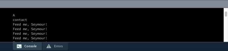
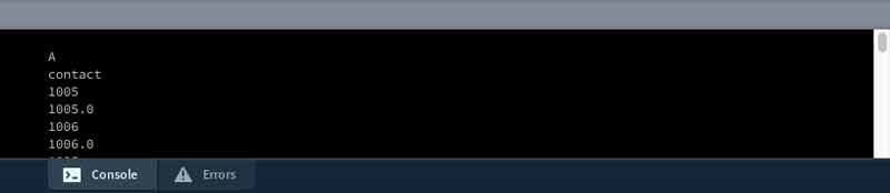
Processing adds and if / else statment within a serialEvent void for confirming contact (based on a new first contact boolean and listening for an "A" from Arduino). Arduino knows there is contact when it receives any kind of meesage through serial. Then, Processing prints whatever is communicating over the serial port and in case of a mouse press, sends a 1. When Arduino sees the 1, it flips the ledState boolean LOW/ HIGH. If you disconnect Processing and try to reconnect, the board needs to be reset because the first establishContact has already taken place on one side while the processing side will wait forever.
import processing.serial.*;

Serial myPort;  // create an object from Serial class
String val;      // data received from the serial port
boolean firstContact = false;  //check if MCU is communicating

void setup() {
  size(200,200);  // draw a window 200x200 pixels
  String portName = Serial.list()[1];  //adjust for your FTDI cable
  myPort = new Serial(this, portName, 9600);  //match arduino
  myPort.bufferUntil('\n'); //'\n is carriage return (new line - end of packet)
}

void draw() {

}

void serialEvent( Serial myPort) {  //put the incoming data into a String -
  val = myPort.readStringUntil('\n');
  if (val != null) {  //make sure our data isn't empty before continuing
    val = trim(val);  //trim whitespace and formatting characters (like carriage return)
    println(val);
    if (firstContact == false) {
      if (val.equals("A")) {  //look for 'A' string to start the handshake
        myPort.clear();   //if it's there, clear the buffer, and send a request for data
        firstContact = true;
        myPort.write("A");
        println("contact");
      }
    }  else { //if we've already established contact, keep getting and parsing data
      println(val);
      if (mousePressed == true) {    //if mouse click in window
      myPort.write('1');        //send a 1
      println("1");
    }
    myPort.write("A");  // when you've parsed the data you have, ask for more:
    }
  }
}
Download project files
I will post links to resources I have found helpful here.
Processing : full circle.
Enough with the tutorials. Now I would like to start putting these together with some kind of simple visual or audio interface connected to sensor readings.
I started by looking at this former Fab Academy student's work mapping phototransistor settings to a dynamically configurable 3D model. He was able to combine sensor readings from arduino with a Processing sketch from Open Processing Org, a wonderful place for sharing processing sketches. I went there with the intention to grab a sketch, however I was a little overwhelmed so instead I started looking at former Fab Academy students' pages for a sketch I might be able to digest.
After some searching, I found Shunichi Mizugaki's Fab Academy Page. He wrote this sketch to make little bar graphs for his accelerometer sensor.
And he was friendly enough to share his code. Which looked like this (for convenience):
import processing.serial.*;

Serial myPort;

int in_x, in_y, in_z;
int cnt;

color[] col = new color[6];

void setup() {
  size(800, 400);
  frameRate(40);
  myPort = new Serial(this, "/dev/cu.usbserial-FT91COUK", 9600);
  initGraph();
}

void draw() {

  //x axis
  fill(col[1]);
  float tx1 = map(cnt, 0, width, 0, width);
  float ty1 = map(in_x, 0, 200, height, 0);
  ellipse(tx1, ty1, 4, 4);

  //y axis
  fill(col[2]);
  float tx2 = map(cnt, 0, width, 0, width);
  float ty2 = map(in_y, 0, 200, height, 0);
  ellipse(tx2, ty2, 4, 4);

  //z axis
  fill(col[3]);
  float tx3 = map(cnt, 0, width, 0, width);
  float ty3 = map(in_z, 0, 200, height, 0);
  ellipse(tx3, ty3, 4, 4);

  if (cnt > width) {
    initGraph();
  }

  cnt++;
}

void initGraph() {
  background(47);
  noStroke();
  cnt = 0;
  col[0] = color(255, 127, 31);
  col[1] = color(31, 255, 127);
  col[2] = color(127, 31, 255);
  col[3] = color(31, 127, 255);
  col[4] = color(127, 255, 31);
  col[5] = color(127);
}


void serialEvent(Serial myPort) {
  if (myPort.available()>2) { // if receiving 3 data from serial (important!!)//
    in_x = myPort.read();
    in_y = myPort.read();
    in_z = myPort.read();
  }
}
On immediate inspection, I see that in one of the tutorials, I have a more elegent, if not potentially flawed solution for establishing communication between the board and the Arduino code in serial. I say flawed, because if the board every drops connection for some reason, the only way to reconnect is to reset the board. I do not need three graphs, just one and I prefer for it to be horizontal.
First the Arduino code is fairly straightforward. I effectively combined what I learned from the tutorials with a simple sensor to serial sketch. After configuring the pins, the board launches the serial connection and begins sending A's while waiting for something to respond with anything. Kind of like our probing outer space with Doritos commercials. I liked that chip when I was a young boy.
// Using an ATTiny44
// This is written to be used alongside Processing for visualizing sensor data
#include <SoftwareSerial.h>
SoftwareSerial mySerial = SoftwareSerial (0,1);    // RX PA1 12, TX PA0 13

// Pin Configurations
const int sensorPin = A2;  // PA2
//const int LED = A7;        // PA7
int sensorValue = 0;       // variable to store the value coming from the sensor
int outputValue = 0;        // variable to store the mapped value
char val;  // Data from serial


void setup() {
  //pinMode(LED, OUTPUT);   // declare the LED as an OUTPUT:
  mySerial.begin(9600);   // Set this the same on serial monitors
  establishContact();  // send a byte to establish contact until receiver responds
}

void loop() {                   // read the value from the sensor every 50 ms
  if (mySerial.available() >0) { // If data is available to read,
     val = mySerial.read(); // read it and store it in val

     if (val == '1') { // If 1 was received
        sensorValue = analogRead(sensorPin);
        //outputValue = map(sensorValue, 0, 1023, 100, 0);  //0 is dark, 100 is bright
        mySerial.println(sensorValue);  // print converted reading to Serial
        delay(200);    // calibrate for stability in readings
     } else {
      delay(200);
     }
  }
}

void establishContact() {
  while (mySerial.available() <= 0) {
    mySerial.println("A");  //send A
    delay(300);   // adjust delay for stability
  }
}
After a response does come, the board sends a reading of the phototransistor to serial everytime it receives a "1". That is the Arduino code. Incidentally, if you are trying to debug, the "1" is not printed to the serial monitor.
Next the Processing side of the code. I will highlight a few chunks first. This is the serial portion of the code, which is similar to the tutorial. Within the else section, I adjusted to no longer use mouse clicks for the LED, instead it grabs the data sent from the board as a string and converts it to an integer. Finally, it communicates a "1" so the board knows to send another reading. Also, null data is culled, which is good.
void serialEvent( Serial myPort) {  //put the incoming data into a String -
  val = myPort.readStringUntil('\n');
  if (val != null) {  //make sure our data isn't empty before continuing
    val = trim(val);  //trim whitespace and formatting characters (like carriage return)
    println(val);
    if (firstContact == false) {
      if (val.equals("A")) {  //look for 'A' string to start the handshake
        myPort.clear();   //if it's there, clear the buffer, and send a request for data
        firstContact = true;
        myPort.write("A");
        println("contact");
        delay(100);
      }
    }  else { //if we've already established contact, keep getting and parsing data
      String [] numbers = split(val, ',');
      float sensor[] = float(numbers);
      println(sensor[0]);
      photoT = (int)sensor[0];
    }
    myPort.write("1");  // when you've parsed the data you have, ask for more:
  }
}
For reading data from the FTDI cable, I like this solution better.
myPort = new Serial(this, "/dev/cu.usbserial-FTH052EW", 9600);
The first half of the void draw section draws the static elements. I thought I could move this into the setup section to save computing effort but the text gets rendered strangely when I do. There are different ways to input color. One is a grayscale value, which is used on the background and fill. Another is RBG, which is used later as three variables. Rectangles in processing are drawn with at least four inputs: X, Y upper left corner coordinates and width and height. In that sequence. Any modifiers will effect everything through the code unless a new modifier is set. For instance, textAlign(RIGHT) will align all text generated after this line of code to the right. Fill(0) is a little strange because it effects vectors and text.
void draw() {
  //[mostly] static elements
  background(255);
  fill(0);
  rect(100,100,500,100);  // (a, b, c, d) (x-coord, y-coord, width, height) x &y are
    upper left corner
  textSize(16);
  textAlign(RIGHT);
  text("LUX", 75, 158);
The second half draws the dynamic elements. I start by mapping the sensor data which is 1023 for totally dark and 0 for light to values to use for reference coordinates and percentages. Then this rectangle is drawn on top of the other, as a teal color defined elsewhere. I made two lines that mark min and max readings recorded in this session and some text labels of each. The min and max are tracked in variables. Finally, decimal points are culled from floating numbers with the round function.
//[mostly]dynamic elements
  float x = map(photoT, 0, 1023, 100, 0);  //map censor values for graphing, 0 is dark,
    100 bright
  int ax = round(x);
  textAlign(LEFT);
  text(ax, 625, 158);
  fill(col[0]);
  if (x > xMax) {
    xMax = x;
  }
  if (0< x && x < xMin) {
    xMin = x;
  }
  rect(100, 100, x*5, 100);
  line(xMin*5+100, 75, xMin*5+100, 225);
  line(xMax*5+100, 75, xMax*5+100, 225);
  int xMaxText = round(xMax);
  int xMinText = round(xMin);
  fill(0);
  textSize(12);
  textAlign(CENTER);
  text ("min", xMin*5+100, 250);
  text (xMinText, xMin*5+100, 264);
  text ("max", xMax*5+100, 58);
  text (xMaxText, xMax*5+100, 44);
}
And finally here is the code in its entirety. I think there is a better solution for the color but in this way, it might be easier to make that dynamic, ie. the color of the graph heats up as the lux reading gets brighter.
import processing.serial.*;

Serial myPort;   // create an object from Serial class
boolean firstContact = false;  //check if MCU is communicating
String val;      // data received from the serial port
int photoT;      // converted string from serial port
color[] col = new color[1];
int ax;
float xMax = 0;    //tracking the highest value recorded
float xMin = 100;    //tracking the lowest value recorded
int xMinText;
int xMaxText;

void setup() {
  size(700, 300);
  frameRate(40);
  myPort = new Serial(this, "/dev/cu.usbserial-FTH052EW", 9600);
  initGraph();
}

void serialEvent( Serial myPort) {  //put the incoming data into a String -
  val = myPort.readStringUntil('\n');
  if (val != null) {  //make sure our data isn't empty before continuing
    val = trim(val);  //trim whitespace and formatting characters (like carriage return)
    println(val);
    if (firstContact == false) {
      if (val.equals("A")) {  //look for 'A' string to start the handshake
        myPort.clear();   //if it's there, clear the buffer, and send a request for data
        firstContact = true;
        myPort.write("A");
        println("contact");
        delay(100);
      }
    }  else { //if we've already established contact, keep getting and parsing data
      String [] numbers = split(val, ',');
      float sensor[] = float(numbers);
      println(sensor[0]);
      photoT = (int)sensor[0];
    }
    myPort.write("1");  // when you've parsed the data you have, ask for more:
  }
}

void draw() {
  //[mostly] static elements
  background(255);
  fill(0);
  rect(100,100,500,100);  // (a, b, c, d) (x-coord, y-coord, width, height) x & y are upper
    left corner
  textSize(16);
  textAlign(RIGHT);
  text("LUX", 75, 158);

  //[mostly]dynamic elements
  float x = map(photoT, 0, 1023, 100, 0);  //map censor values for graphing, 0 is dark,
    100 bright
  int ax = round(x);
  textAlign(LEFT);
  text(ax, 625, 158);
  fill(col[0]);
  if (x > xMax) {
    xMax = x;
  }
  if (0< x && x < xMin) {
    xMin = x;
  }
  rect(100, 100, x*5, 100);
  line(xMin*5+100, 75, xMin*5+100, 225);
  line(xMax*5+100, 75, xMax*5+100, 225);
  int xMaxText = round(xMax);
  int xMinText = round(xMin);
  fill(0);
  textSize(12);
  textAlign(CENTER);
  text ("min", xMin*5+100, 250);
  text (xMinText, xMin*5+100, 264);
  text ("max", xMax*5+100, 58);
  text (xMaxText, xMax*5+100, 44);
}

void initGraph() {
  col[0] = color(31, 255, 194);  // R, G, B values
}
Download project files
I will post links to resources I have found helpful here.
Fireflies and grasshoppers.
I would like to start with the Firefly plugin in Grasshopper and see if I can control a stepper motor. If I can get a successful start with that, then I might be able to incorporate dishuBot controls through Grasshopper/ Firefly rather than GRBL. This would be directly connected to my G-code transcoder. There are a few challenges. One, Firefly has not been released on the MacOS, my operating system. Two, I need to learn to setup code for the board to accept commands through serial from Firefly.
This is an example of Firefly reading and parsing live hand tracking from a Kinnect. One short step from outputting data to steppers...
This is an example of Firefly controlling a walking 3D printer robot that is simultaneously sensing and adjusting for terrain differentiatios.
And there are many more fantastic precedents here.
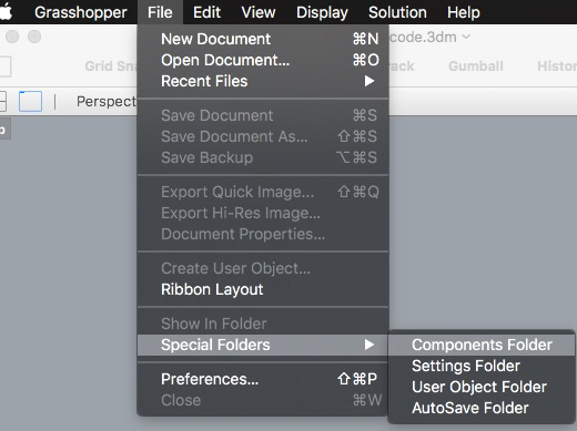
First I had to find a way work around the installer and use the grasshopper and arduino components on a Mac. Download the installer. I tried to extract the files using a few different unpackers on macOS but was only left with unusuable files. If you have access to a Windows machine, you can download this. Extract the files from the installer. Then, return to your mac and copy the Grasshopper files into the components folder. Open Grasshopper, click here:
Relaunch Rhinoceros. Start Grasshopper. I get the following errors, yet the application loads and seems stable. First step down.
Object: WebCam_VideoStream (level 1)
{
  Exception has been thrown by the target of an invocation.
  TargetInvocationException
}

Object: WebCam_VideoStream (level 2)
{
  An exception was thrown by the type initializer for Firefly_X.WebCam_VideoStream
  TypeInitializationException
}

Object: WebCam_VideoStream (level 3)
{
  Invalid IL code in C_sawapan_media.MediaIO:Initialize (int): IL_0002: call      0x06000111


  InvalidProgramException
}
Do you like tutorials? You can do that. First install the firmata to Arduino. I had to use Arduino IDE 1.0.6 for this. First I will try to control a stepper motor with a spare Arduino Mega cross RAMPS shield. From the notes of the sketch:
2. Select your specific Arduino Board and Serial Port (Tools > Board; Tools > Serial Port) *Take note of your Serial Port COM #
3. Verify (play button) and Upload (upload button) this program to your Arduino, close the Arduino program
4. then open ... Rhino/Grasshopper/Firefly
Note: The Firefly Firmata sets the following pins to perform these functions:
*****ON MEGA BOARDS (ie. ATMEGA1280, ATMEGA2560)*****
ANALOG IN pins 0-15 will return values (from 0 to 1023) for 16 analog sensors
DIGITAL IN pins 22-31 will return 0's or 1's; for digital sensors (buttons, switches, on/off, true/false, etc.)
DIGITAL/ANALOG OUT pins 2-13 can be used to digitalWrite, analogWrite, or Servo.write depending on the input status of that Firefly pin
DIGITAL OUT pins 32-53 can be used to digitalWrite, Servo.write, or analogWrite depending on the input status of that Firefly pin
Next connect the serial monitor in Grasshopper. Here, I am having problems.
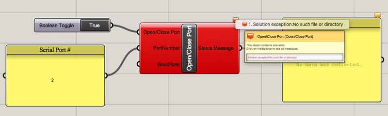
Unable to solve the serial port communication problem, I was spurred to add capabilities. Now I can also Steam on Windows. I installed using Bootcamp. I did not need to go to any extremes such as reinstalling MacOS. I simply launched Bootcamp, downloaded some material to a neutrally formatted USB memory, dictated a partition size and installed Windows. I had a rush of nostalgia from my childhood.
I will return to this, likely after my final work. Former Fab Academy student Francesca Perona, from the point of view of a MacOS user, walks through installing the necessary components (Windows, Rhinoceros, Grasshopper, Firefly, Arduino) gathering data from a sensor and operating an LED using Firefly. Enrico Cacciapuoti uses Firefly to control an Arduino Uno x CNC Shield combination, not coincidentally akin to the setup of dishuBot.
I will post links to resources I have found helpful here.
Jump : Index
J.travis Russett © 2017
 All the work contained within is licensed under a Creative Commons Attribution-NonCommercial-ShareAlike 4.0 International (CC BY-NC-SA 4.0) License
You may remix, tweak, and build upon my work non-commercially, as long as you credit me and license your new creations under the identical terms.