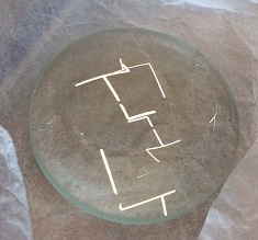
For vinyl cutting design, I used Inkscape.

For the laser cutter, I can use Inkscape (spirograph from last assignment), Fusion360, and SolidWorks.
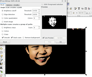
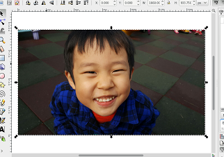
1. I opened and then selected the picture I want to use in Inkscape.
2. Then chose : Path>Trace Bitmap. I can play with the mode. Live preview is useful again.
3. After removing the original one, I applied (Path > Simplify) to the traced image, and also reduced the size when exporting it to png file.

(If you really like to use this file since you think he is so cute, then I will allow you to do so~ Download this image.)
1. Open Silhouette studio and open png file.
2. If needed, change the size here (on the upper right side):
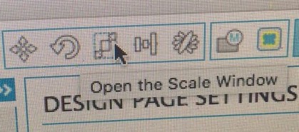
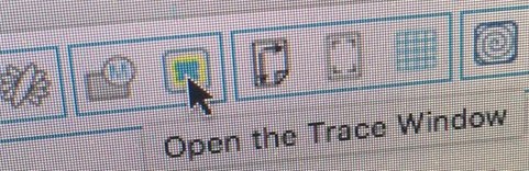
3. Open trace window:
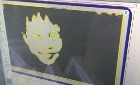
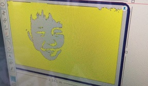
4. After selecting trace area, play with the values of high pass filter and low pass filter.
With low 'high pass filter' (1.00)
With high 'high pass filter' (61.00)
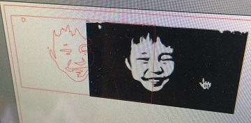
5. Clicking 'trace' will generate trace, and by moving the original picture (and then deleting it), I can get trace file.
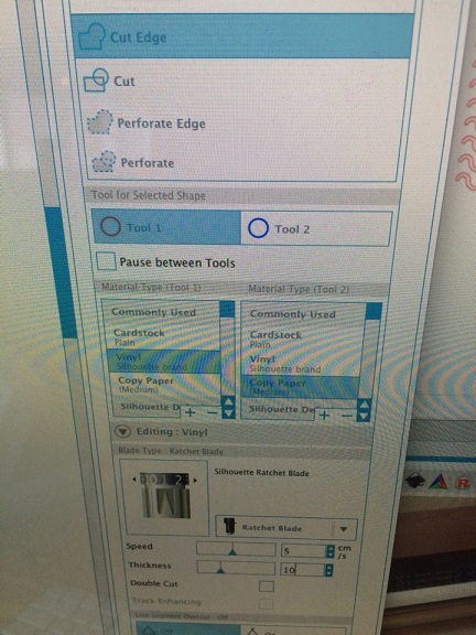
6. Choose 'Silhouette > Cut setting', and set in the following way:
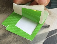
7. Using double sided transparent tape, attach the sticker, place it so that it can align with the arrows, and lift up the lever on the other side.
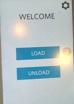
Now Click 'load'
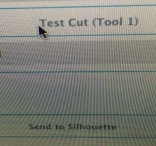
8. Click 'test cut' and then 'Send to Silhouette'. It will cut the figure.
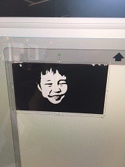
9. Using masking tape, detach it from the paper, and then apply it on any surface!
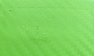 (It doesn't look clear from this side, but...)
 (after doing this..)
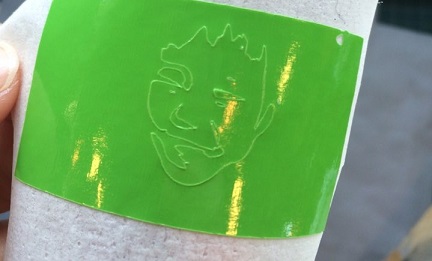 (..it looks much better from bottom)
My little Hulk!!!

- setting: speed=10, power=80-85%
- used this file (fusion360)
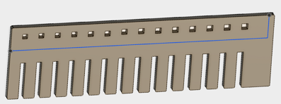
so that the widths increases by 0.05mm, and it starts from 2.55mm.
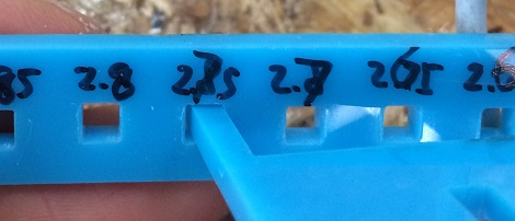
When I put it horizontally, it was quite hard to push,
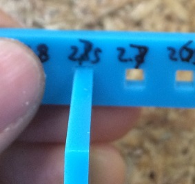
but when I did the same thing vertically, it was easier. I don't know how this can happen. The kerf for both sides should be the same, so the square should remain to be square. I couldn't find the answer yet.
Anyway, it seems like 2.75 is proper value to choose for 3mm acryl with the above setting.
Used: Fusion 360
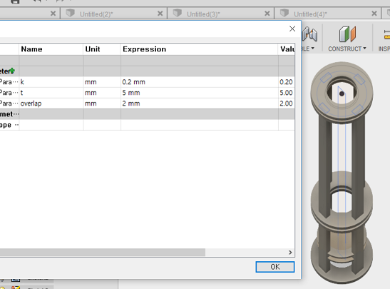
I can use parameters from 'Modify'>'Change parameters'
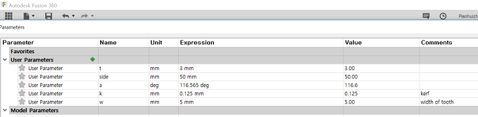
Since I wanted to apply kerf from both sides, I used k=0.125mm for each.
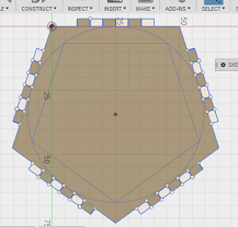
I used the same setting as the above: speed=10, power=80-85%.
(I can draw pentagon using polygon option.)
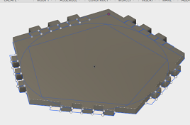
Download files here: dxf file and Fusion 360 Archive File.
Actually, I cut even the spirograph I did for week 2 by the laser cutter, and did some kerf test, but lost the result. This is why documentation is so important. (More precisely, instant documentation.) 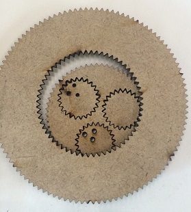
UPDATE after getting feedback
- To include parametric design file, I needed to make a new file.
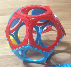
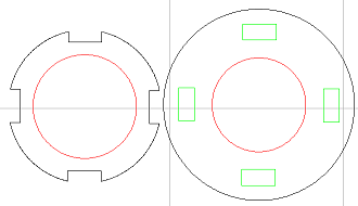
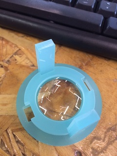
- I already had two small convex lenses, so wanted to make a simple microscope with them.
- The lenses fit in 2, and the inner circle of 1 and 3 is a bit smaller than the one of 2 by 'overlap', so it does not escape. For the bottom of microscope, I can use the same 1 (or 3).
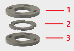
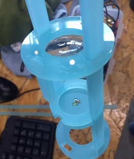
- Besides installing two lenses, I also place the following to put small object:
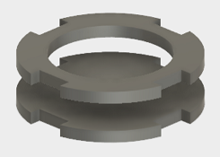 - The upper part will stay fixed, and the lower one can move for focusing.
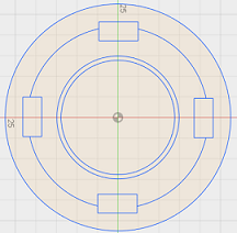
- As for the legs of microscope, I planned to use 4 legs, but soon realized that it is hard to put objects on the plate. So I used only two legs, and used small bars to fix three plates that hold each lens.(Since I applied kerf for the plates, actually legs of design file are bigger than the holes.)
- Powercut setting:
1. Open Powercut.
2. Load dxf files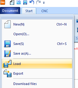
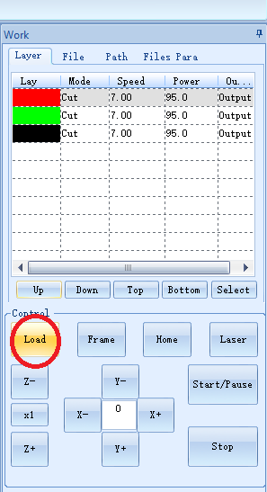
3. Click and change the colors according to the order (inside first).
4. Click color of the right upper side to change setting (also change the order).
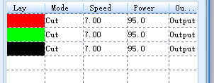
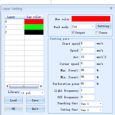 (Speed=7, power 95%)
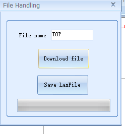
5. Click "Load"
6. Click "Download file"
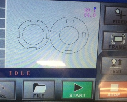
- Laser cutter setting:
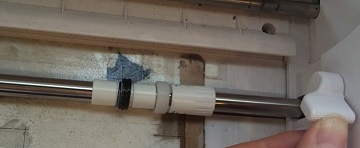
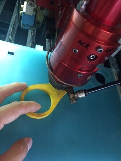
1. Using controller, set the origin. For z origin: The following yellow part should be slightly movable. (This can be different depending on the machine, lab, and of course that yellow part!) Then click 'ESC'
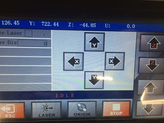
2. Click 'fixed', and then 'frame' to see if the area is inside the material. Then click 'Start'!
3. Open it after (at least) 10 min.
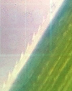
- The outcome:
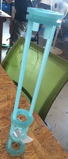
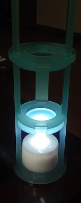 It works much better with a light.
Now I can see why the edge of the grass is that hurting!
Download files here: Fusion360 file, dxf files
Note: I used press-fit with this microscope since I hardly need to move the lenses, and as for the object, I only need to move the lower part. As long as they are adjustable, it is better to be fixed.
