Assignments:
            - Add an output device to a microcontroller board you've designed and program it to do something
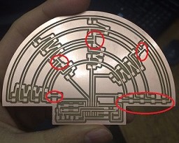
Jellyfish (20 LEDs)
Modification of hello.array.44.2
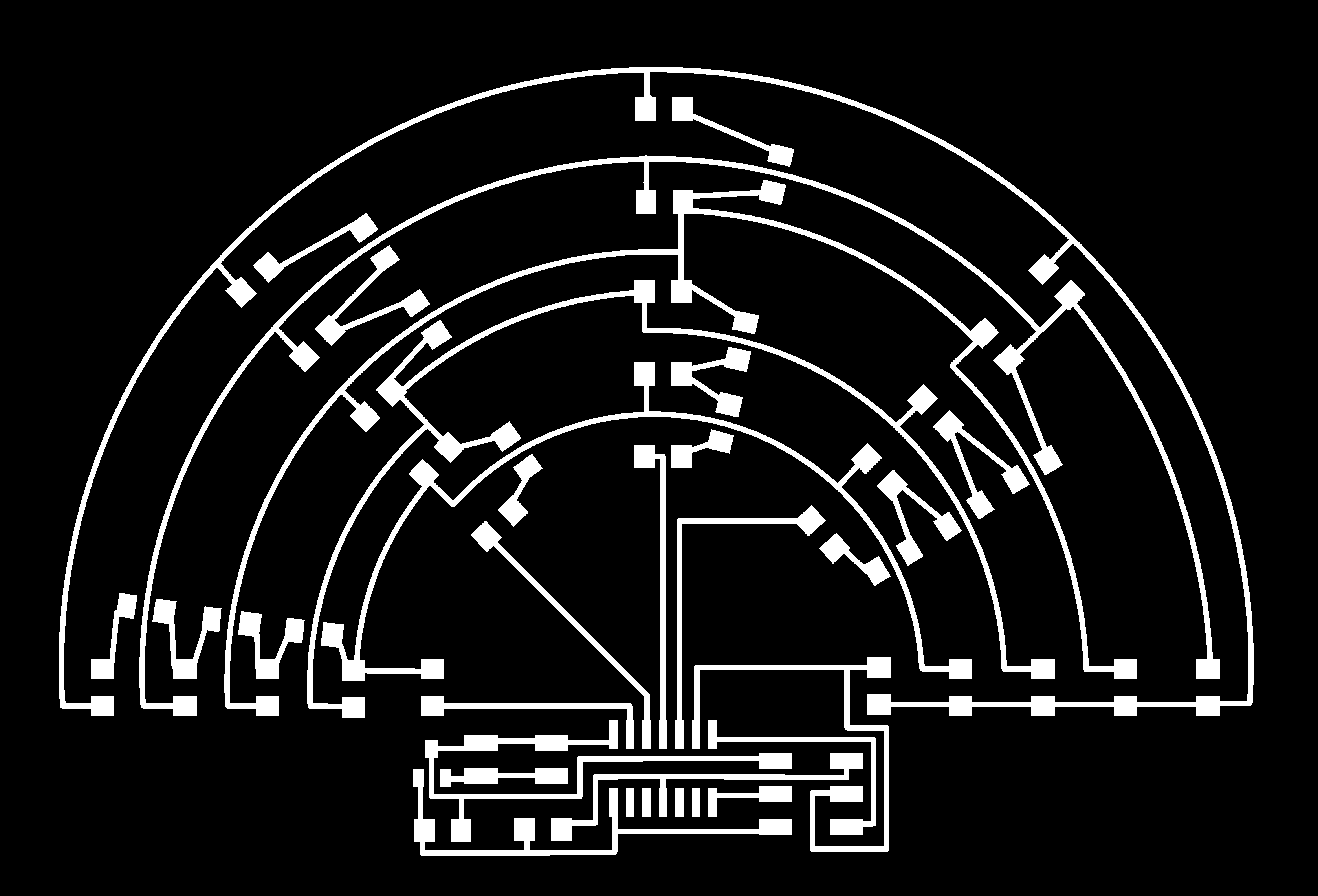
Although the mechanism of Charlieplexing is not so difficult to understand, it wasn't easy to display 20 LEDs so that each one is assigned to each ordered pair of pins. For example, LED12=(pin1,pin2), LED21=(pin2,pin1), and so on, with five pins (so maximally 5*4=20 leds). So I followed the same schematic as hello.array.44.2 except the use of jumpers and copper line connecting all the pins for 5th row.(It was redundant in hello.array.44.2 board.)
These are the differences from hello.array.44.2.
The following numbers are connected pin numbers (arduino pin number).
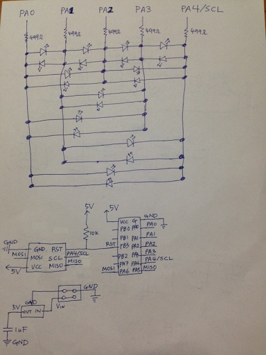
schematics
- Parts: IC regulator(LM3480), attiny44, Resistor:10k,5x499,12x0, Capacitor:1uF, 20 LEDs
- Each led is designed to be connected to two pins.
- After soldering, I checked with multimeter, and there was a short somewhere since pin 1(+) and pin 2(-) lighten two leds(LED11, LED12), not one led. I checked all the cases, and from them, could guess that there must be a short between row 2 and 3/culumn 2 and 3, and found very thin copper line connecting row 2 and 3 on column 3!
- Next, uploading hello.array.44.2.c file was successful, but the outcome was very different from what I expected. I should figure out why.
- So I wrote an arduino code:HERE, and it works!
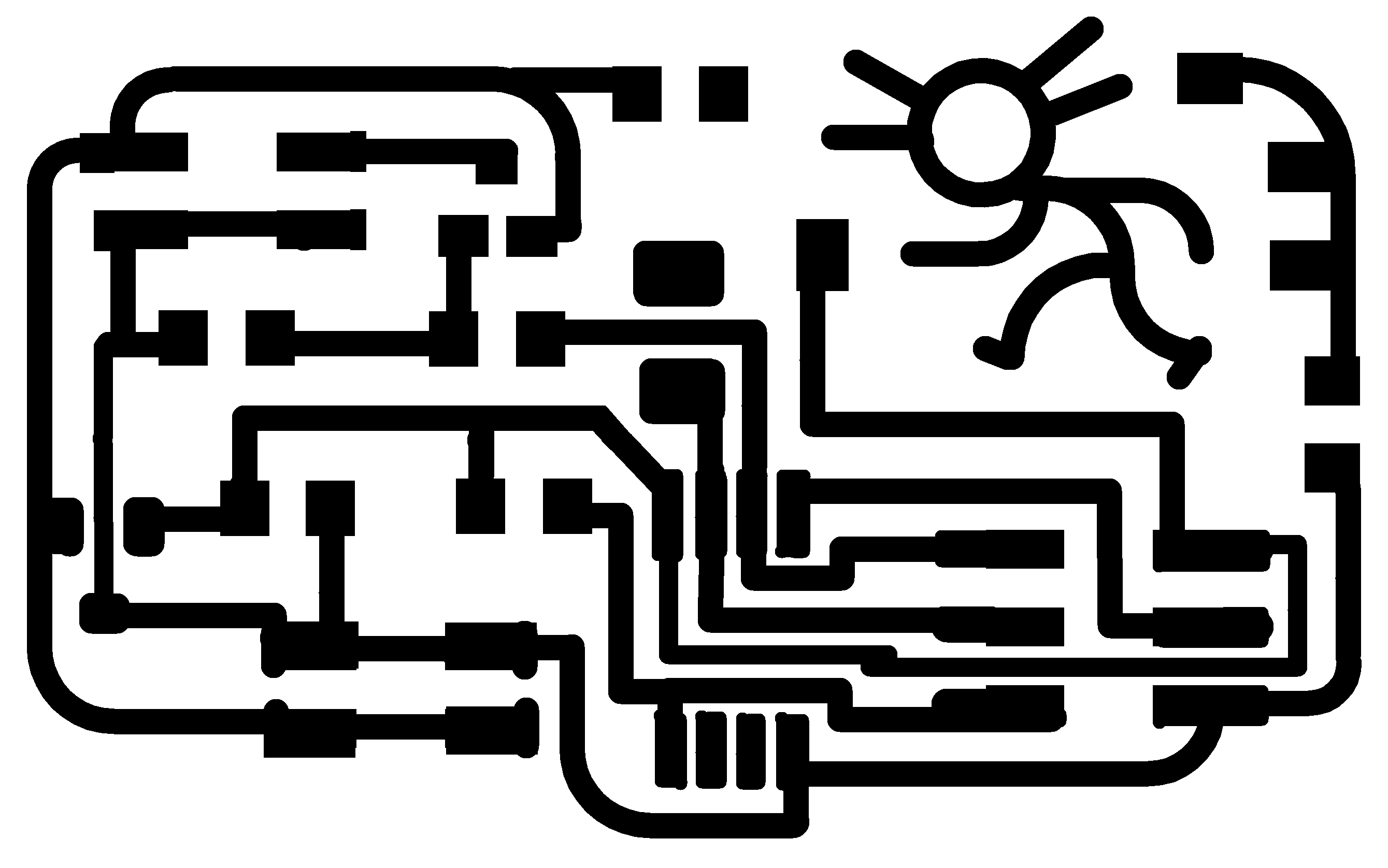
- As both Edu and Neil mentioned, I included two additional resistors: having a resistance(~100 Ohm) between MCU pin and G(gate: mosfet) helps the change in flow to be smoother, and having another (~1kOhm) between GND and G works as pull down resistor.
- I connected S(Mosfet source) to Vcc, not GND, and also modified positions of Vcc and GND of power supply.
- I also wanted to try muscle wire here later with connection to a pin and with some resistance maybe (green). So I included some extra pads for them. For now, I didn't solder anything. It can be connected anytime later. I also adjusted the pad sizes by drawing some outlines (and sometimes by erasing the original shape from EAGLE) so that soldering gets easier.
- And since I used vinyl cutter to make this PCB, and vinyl cutter makes the copper line quite thin (both in picking up the trace and in cutting actual copper line), I made the lines quite thick (0.016-->0.032).
(You can download the file.)
- Soldering components on the flexible copper line was actually easier, but I could feel the weak connection between the copper tape and the epoxy film. Edu recommended to use glue gun for this, and now my flexible PCB looks not quite flexible:
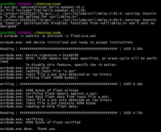
- Then I successfully uploaded hello.speaker.45.c and connected it to power, but it didn't make any sound. I raised the power a bit, and then ... it became a smoker, not a speaker..
- Even now, I can't quite understand the datasheet of speaker(GC0351M). I should understand this first.
- Although I cannot use this board for speaker, I can still use it for other output devices which require higher voltage such as 12V led strip.
MISC.
Tentacles: muscle wires
(The original plan was to connect muscle wire to the circuit so that they can provide some movement to the tentacles. It will help me to practice programming as well. But I didn't do it yet. Later.)
-For now, I just tested its response by connecting it to Fabisp. -The feature of wire is: Flexinol HT(High temperature-activated at 90), diameter:300 micro meter (0.0003 meter), resistance:12.2Ohm/m, recommended current: 1500mA=1.5A.
-I cut 0.18m(~((3.3V/1.5A)Ohm)/(12.2(Ohm/m))(I am not sure if this is the right way to calculate) and connected them to Vcc and GND of 6 pin ISP. See how it reacts:
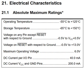
But actually it was very reckless behavior. See the following. Its (attiny45) max DC current between Vcc and GND pins is 200.0mA. 1.5A is almost 8 times as big.. Fortunately, even after trying this several times, my ISP was okay.
Feedback from Bas: In this case, the current does not flow through Attiny45. Maybe the above calculation is right! (I am afraid I cannot find the exact datasheet.)
 These are the differences from hello.array.44.2.
 schematics


