Hello, everyone!
Let's start this assignment!
In this assigment, I have:
To design microcontroller board;
To fabricate it;
To program it to do something.
I decided to do anything complicated, and try to make a PCB with the minimum possible size.
With using clothespins(with connectors) and minimal additional components (No RST-button, no external crystal, etc).
List of components:
ATtiny45;
1206 LEDs;
1206 0.1 cap;
1206 10k res;
1206 1k res;
PLA (90deg) 2.54mm pins;
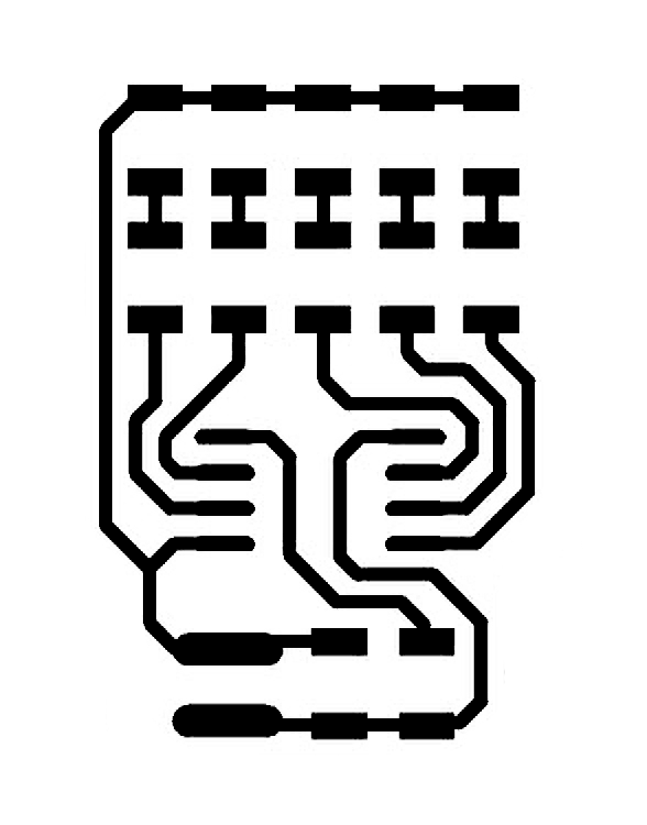
Place of components.
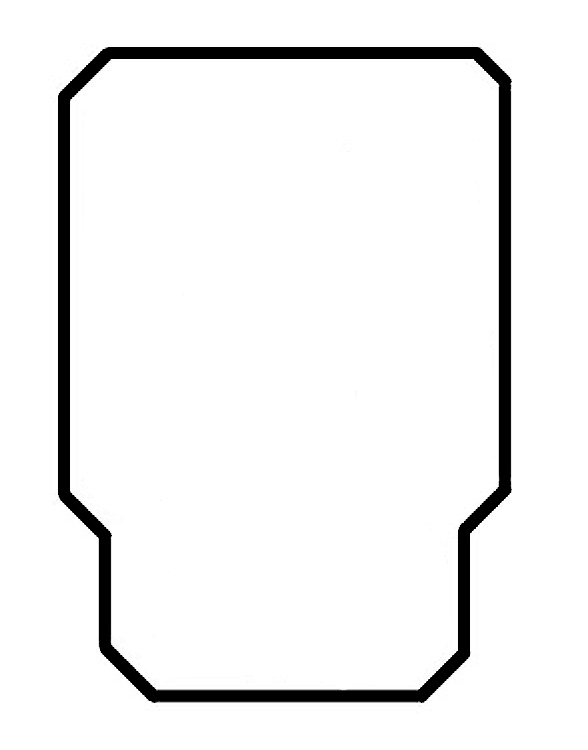
The look of the PCB.
Import Gerber files into CopperCAM.
Creating pathways of milling.
Milling procces.
Milled PCB.
The final view of board with soldered components.
An arduino code of blinking. More about sewing you can see at embedded programming assignment.
#define LED_1 0
#define LED_2 1
#define LED_3 2
#define LED_4 3
#define LED_5 4


void setup()
{
  pinMode(LED_1, OUTPUT);
  pinMode(LED_2, OUTPUT);
  pinMode(LED_3, OUTPUT);
  pinMode(LED_4, OUTPUT);
  pinMode(LED_5, OUTPUT);
}


void loop()
{
  digitalWrite(LED_1, HIGH);
  digitalWrite(LED_5, LOW);
  delay(100);
  digitalWrite(LED_2, HIGH);
  digitalWrite(LED_1, LOW);
  delay(100);
  digitalWrite(LED_3, HIGH);
  digitalWrite(LED_2, LOW);
  delay(100);
  digitalWrite(LED_4, HIGH);
  digitalWrite(LED_3, LOW);
  delay(100);
  digitalWrite(LED_5, HIGH);
  digitalWrite(LED_4, LOW);
  delay(100);
}
And a video of the LEDs blinking :)
About problems :)
To download the Altium project click here .