Final project
Requirements summary:
- be my own design
- include a fabbed input device and an output device of my own
design
- include other components made with additive and subtractive
techniques
- include 2D and 3D design elements.
I thought this task many times and many months earlier before the
Fab Academy started. I talked with my colleagues who participated
Fab Academy last year.
I had many choices and finally I took my ongoing project at home. I
am doing conversion to my car to camper use. And, I need controller
system [c] to guide heating system there.
Idea of my project

The control system might control heating of rear passenger
compartment. It has separate rear heating system [h] that
take energy from motor [m] cooling system.
When motor runs, the cooling system circulates the liquid and blower
circulates the air in the compartment.
But when I stop the motor, the cooling system still has the energy
available. And, I want utilize it. As well as, my car has electrical
preheating system for motor.
It is only 550 Watts, but I might be able to preheat little also the
compartment inside.

Now, I have plan to add an electrical pump [p] to the
cooling system and control both pump and the rear blower. So, I need
some temperature measurement system, control panel, controller and
motor drives do this.
In addition, I am interested in voltage level of my car's battery.
How much can I discharge it, so that the car can start anyway.
How much energy (E) I can utilize? Mass (m) of motor is about 200 kg
and typical temperature drop (△t) I can use is
about 80 to 20 °C. Further, specific heat capacity (c) of steel is
500 J/(kg K).
I guess I use this amount energy typically for one hour. Therefore,
I can stop one hour and enjoy warm car in winter time (~ 0 ºC).
Maybe some energy loss exists.
Let see can I do it.
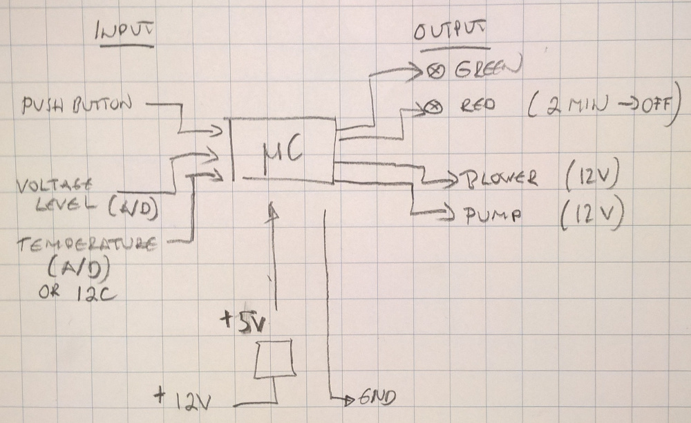
I drew a following sketch of electrical connections. There are two
leds, green and red, and one push button switch as a user interface
to the control system. I call it a user panel. Why so
little? I would like to use it, when I drive my car.
And, those are enough to keep my interest in driving. As second
reason, I try minimize energy consumption, when it operates as
battery-driven without help of motor.
Modeling of the control panel
I have done 3D modeling of a cover part for my user panel as assignment 2. I can select
color for it and put in "place".
Here we go.
Thinking controller
I think I can use ATtiny45 or ATtiny85 as my controller core.
Atmel describes ATtiny45V microcontroller as it combines 4KB ISP
flash memory, 256-Byte EEPROM, 256B SRAM, 6 general purpose I/O
lines, 4-channel 10-bit A/D converter, operation between 1.8 - 5.5
Volts. Power Consumption is 300 µA in active mode, 1 MHz and 1.8V.
My project needs 7 I/O lines. I must reduce them to 6 or change
microcontroller, for example, to ATtiny44 with 12 I/O lines.
- push button to control the operation e.g. start and stop the
system (Digital input)
- temperature measurement (A/D conversion)
- voltage measurement (A/D conversion)
- rear blower control (Digital output)
- external pump control (Digital output)
- communication LED (Digital output).
Output devices
 Further, I examined that I
can use MOSFET component to operate 12 V devices via 5 V control
voltage from ATtiny. Those MOSFETs need heat sink to cooling.
Further, I examined that I
can use MOSFET component to operate 12 V devices via 5 V control
voltage from ATtiny. Those MOSFETs need heat sink to cooling.
ATtiny operates 5 V voltage and it can be produced
from car 12 V voltage by a regulator.
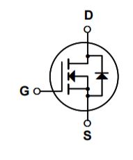
For example, N-channel MOSFET FQP30N06L can control 60V or
30 A devices. ATtiny's any output connects to G pole with a 10k
pull-down resistor to GND.
S pole connects to GND and D pole to a pump or blower minus
(-) connector. A rectifier diode like the 1N4001 or SB560 connects
between motor connector as direction (white band) to +.
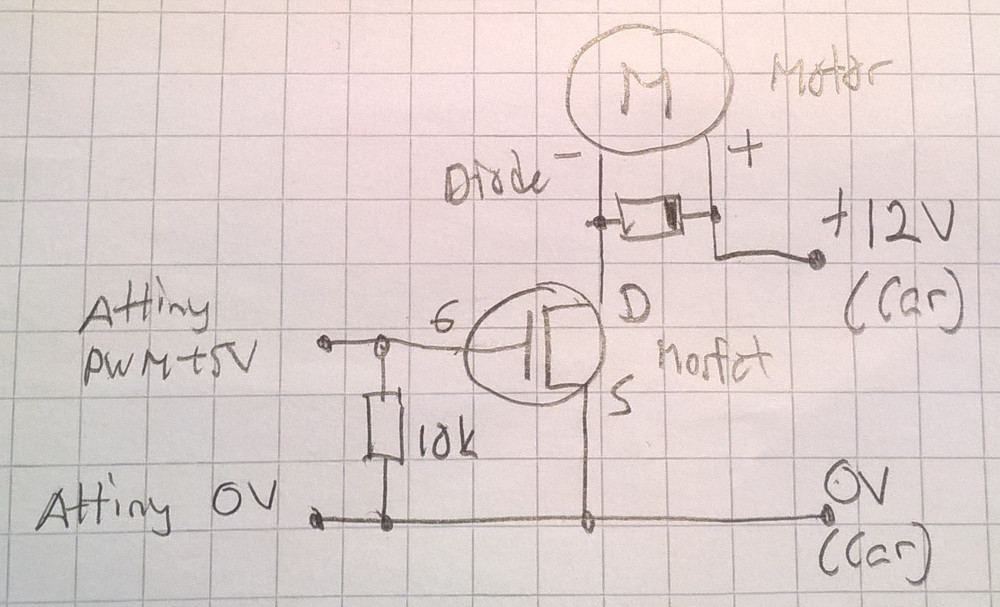
Pump needs about 5 W power. Blower needs maybe more about 40W.
Following picture shows the wiring of the rear blower.
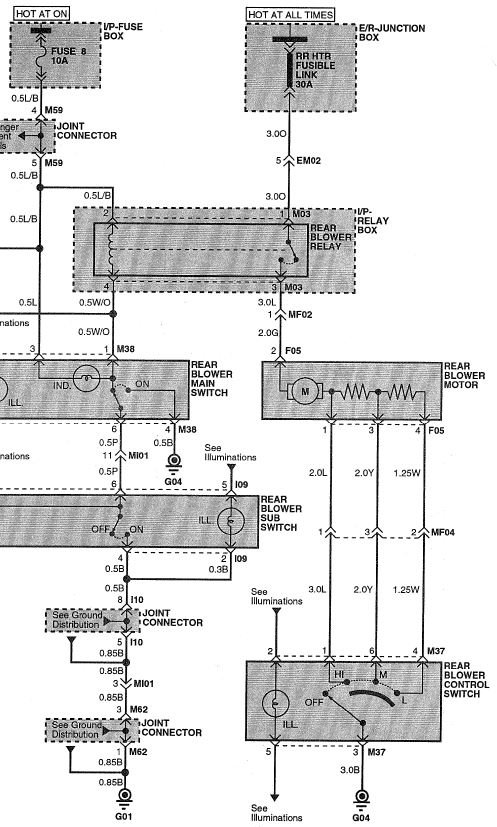
As a part of my new rear heating control I might change wiring by
connecting the on/off switch input of the rear blower (F05)
permanently to +12 V.
And, use my controller to connect the blower to ground (G04).
When I studied wiring schematic more carefully, I found blower is
controlled by a relay.
And, the relay input is powered always +12 V. Therefore, I need only
control this relay.
Further, it is done easily by adding connection to the ground via my
control system.
No, the third look explains that relay control get on only when
ignition key is turned position ON. Therefore, my control system
must connect +12 V to the relay control input to activate the blower
or I can add second relay as parallel to original relay. And, a user
can switch blower on and off normally by the switch. However, a
relay needs much less power to control than blower, about 5 W,
I guess.
I can use same relay to control pump and blower relay also.
I sketched a storage box for my camper car and milled end plates of
it as an assignment 7.
I designed a pump and relay control as an assignment 10. The pump
rotates only to one direction. The relay controls the blower as
described earlier.
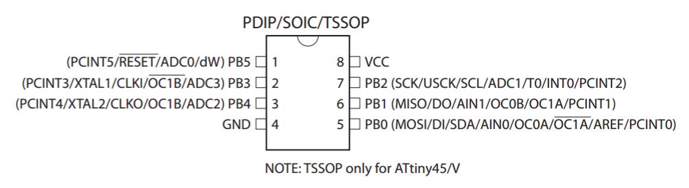
My solution uses 12 V operating voltage from my car. It is lowered
to 5 V for Attiny44 use by regulator ZLDO17-50. Maximum supply input
voltage for this regulator is 18 V and current 1 A. I changed
the microcontroller to Attiny44, because it has 12 I/O pins, enough
for my application. I simplified my board using in-circuit clock. A
motor and a relay are controlled by two N-MOSFETs, of type
NDS355ANCT. They have maximum values as 30 V and 1.7 A. Further, I
protected them by diodes BAV103 for reverse spike voltages. It's
reverse voltage is 200 V and forward continuous current 250
mA. Big connector plates are needed for 12V control wires I
solder there. All other connections are handled by 1x12 pin header,
because I want flatten the board and need programming pins MISO,
MOSI and SCK for other purposes, maybe.
I use pins PA0 and PA1 for pump and relay use. Pin PB2 can be
used as interrupt (INT0) and wake-up purposes. And, PA2, PA3 or
PA7 can be used for analog-to-digital conversion (ADC) purposes.
Hence, they can be used for temperature and battery voltage
measurements. Minimum voltage level could be detected by certain
Zener diode also. Finally, I connected two leds to pins PB0 and
PB1.
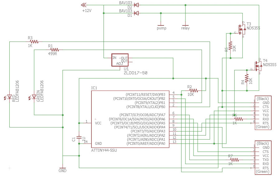
Note:
RED LED is connected to PB1 and
GREEN LED to PB0 in final board
(see note in Assignment 10).
Input devices
Analog-to -digital conversion is totally new thing for me. Attiny44
has 10 bit resolution of ADC and 8 channels. I made test board to
study more of this feature as assignment
13. I want measure supply voltage (12 V) of my car battery and
temperature inside the car. My test board include two voltage
dividers: One use 2x100k resistors to drop voltage from maximum 15 V
to Attiny44's measurable level 5 V on ADC pin and then 100k resistor
from ADC pin to ground. The second use 10k resistor from 5 V to ADC
pin and from there NTC thermistor to ground. NTC type is NAQ103B
375T10. Thus, it's parameters are R25 10 kΩ and B (25/85) 3750.
Power consumptions of these voltage dividers are 50 µA for voltage
measurement and 250 µA for temperature measurement. Both together
take 300 µA. Not much, but still I might use a main switch for the
system. Then, I can switch it off when I don't need it.
During assignment
15, networking and communication, I made a board for
communication but also for testing of ADC, user interface and serial
communication together. My original ADC code needed some
modifications to work also in Attiny45. One difference
exists as ADLAR set in ADMUX |register for attiny45 and ADCSRB
register for Attiny44.
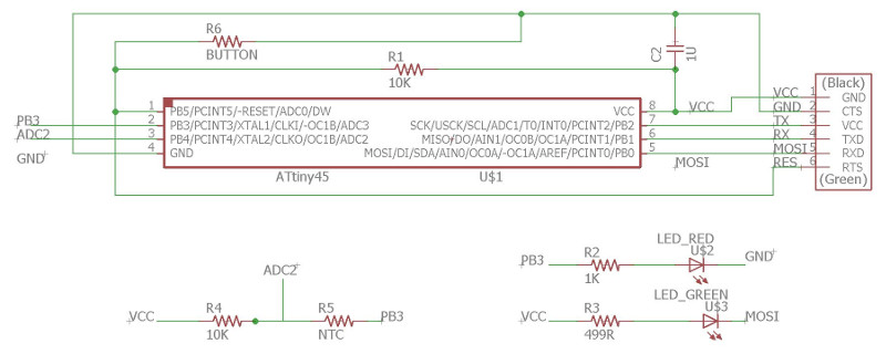
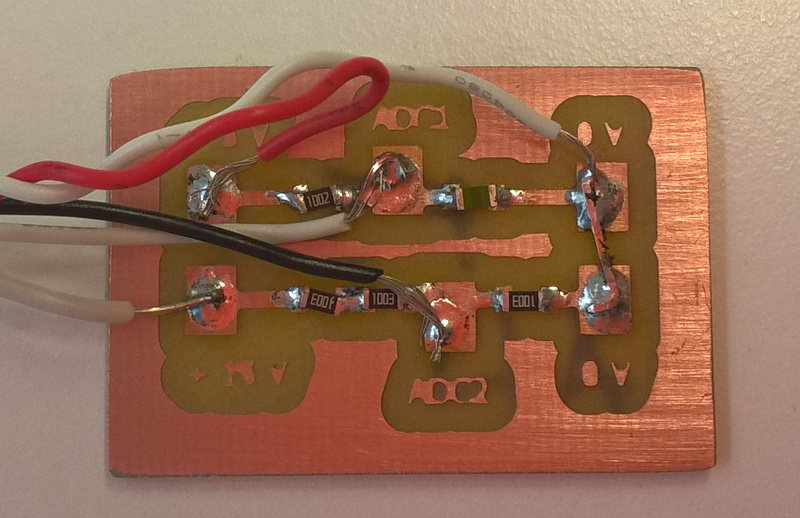
This schematic is for Node_F1.
I must change pins TX and RX that I can use direct cable between
units.
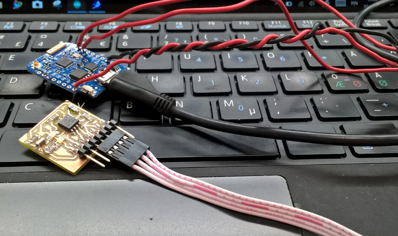
I used Wemos D1 Mini Pro as serial interface to my computer. It's
operating voltage and I/O levels are 3.3 V, but I used it's 3.3 V
pin as voltage source for Attiny45. Therefore, Attiny45 operated
also as I/O levels 3.3 V. Empty code programmed to Wemos
served as serial interface to my Node board.
It is RESIDUAL HEAT CONTROLLER
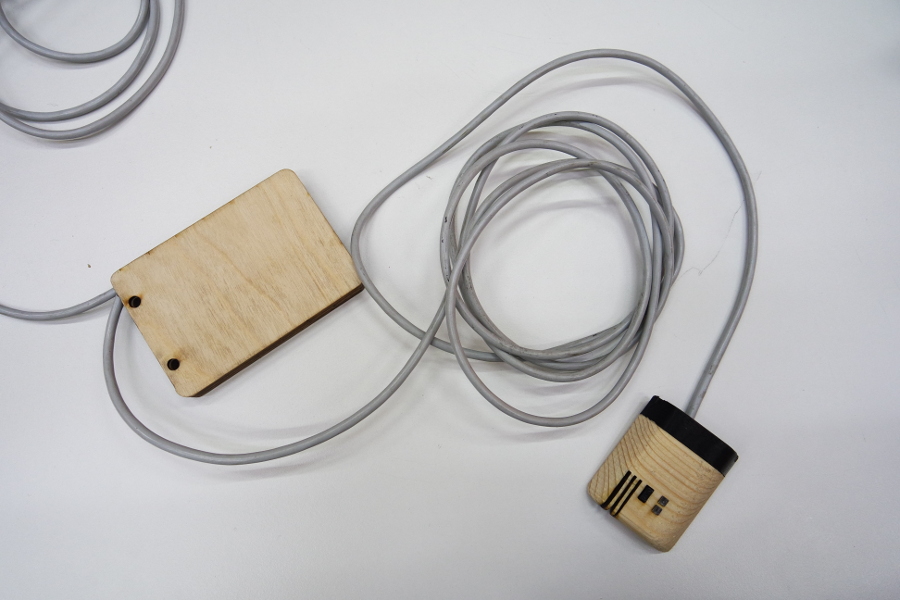
Now is time to document the final project plan. I need two boards,
one (Node_F1) for user interface and temperature measurement
and the second (MainB_F1) for voltage conversion from 12 V to
5 V, battery voltage level measurement and control of pump and
blower. I want use a serial bus between units and such a way that I
can add more boards if needed.
Hardware
Node_F1 board was presented above. I made it during
assignment 15 as I told earlier.
MainB_F1 board is a evolution of boards made during
assignment 10 and 13. It is presented below.
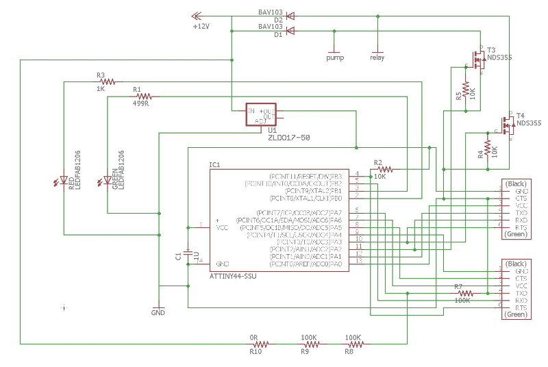
This schematic is for MainB_F1.
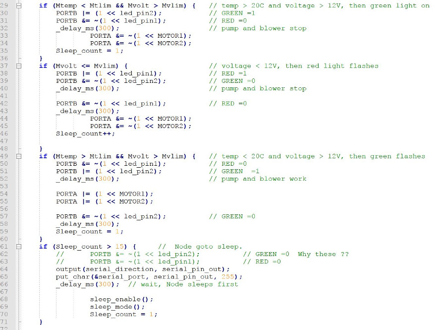
These two boards are handmade soldered and work now. They measure,
communicate and control as designed. Some problems existed. Attiny44
as a core of MainB_F1 took too much power and I changed the chip.
Current consuming was 140 mA and it heated much. After change
current dropped to 14 mA. Also, serial communication needed
different bit delay times. MainB_F1 needed value of 100 and
Node_F1 105. And, I changed TX and RX pins to Node_F1 that I can
use direct cable between units.
Power consuming of two boards was about 12 V 25 mA and it dropped to
12 mA when both boards slept. I done more measurements and saw that
Node_F1 took 5 V and less than 1 mA current. when it slept. And,
MainB_F1 took 5 V, 12 mA even it might sleep. Why? It doesn't sleep
anymore or sleeps shortly and wakes up again. I studied my code and
found error. MainB_F1 sleeps before Node_F1 and it wakes MainB_F1
before sleeps. I corrected my code and now power consumption during
sleep is 12 V 5 mA and during idle 12 V 25 mA. It might be even
lower by some code changes.
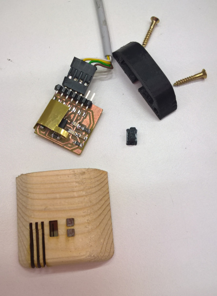
Cover for Node_F1 (left) consists of three parts: the wood box was
made by long Ø3.18 mm bit as two sided. The outer form was milled
first. Then the block was rotated upside down and milled the
inner pocket. I used two holes for targeting means. Then, led and
ventilation holes was cut by laser. Also, two small windows were
laser cut from 3 mm PMMA sheet. The cap and button were 3D printed
from ABS by Statasys Fortus 380mc printer. The brass spring was
handmade by scissors.
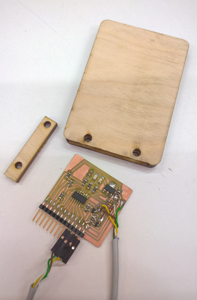
Cover for MainB_F1 (right) is more simpler. It consists of two
parts: the plywood box was laser cut as four parts and glued
together. The cap was made similarly from two parts.
Software
I developed and tested many software parts earlier. I coded LEDs and
Mosfets for pump and relay control as assignment
10, ADC input during as
assignment 13 and serial communication as assignment
15, This communication code originates from Neil's
hello.bus.45.c code from Fabacademy 2017 pages. Also, I tested sleep
and wake-up functions during assignment
8.
Here, I describe final part, operations how software works in
different situations. The both boards have very similar functioning.
Voltage (Mvlim) and temperature (Mtlim) limits are not final and may
change later, when I install the system to my car.
Bill of materials (BOM)
Source column in following list documents the source where component
or material were purchased. Abbreviation FL means from Fab Lab Oulu
and OT means other source.
MainB_FI:
Part
Value
Device
Package
Description
PROD_ID
SOURCE
PRICE EUR
C1
1U
CAP-UNPOLARIZEDFAB
C1206FAB
FL
0.07
D1
BAV103
DIODESOD123
SOD123
DIODE
OT
0.35
D2
BAV103
DIODESOD123
SOD123
DIODE
OT
0.35
GREEN LEDFAB1206
LEDFAB1206
LED1206FAB
LED
FL
0.15
IC1 ATTINY44-SSU
ATTINY44-SSU
SOIC14
FL 1.18
R1 499R
RES-US1206FAB R1206FAB
Resistor (US
Symbol)
FL
0.01
R2 10K
RES-US1206FAB R1206FAB
Resistor (US
Symbol)
FL
0.01
R3 1K
RES-US1206FAB R1206FAB
Resistor (US Symbol)
FL 0.01
R4 10K
RES-US1206FAB R1206FAB
Resistor (US Symbol)
FL 0.01
R5 10K
RES-US1206FAB R1206FAB
Resistor (US Symbol)
FL 0.01
R7
100K
RES-US1206FAB R1206FAB
Resistor (US Symbol)
FL 0.01
R8
100K
RES-US1206FAB R1206FAB
Resistor (US Symbol)
FL
0.01
R9
100K
RES-US1206FAB R1206FAB
Resistor (US Symbol)
FL 0.01
R10 0R
RES-US1206FAB R1206FAB
Resistor (US Symbol)
FL
0.01
RED LEDFAB1206
LEDFAB1206
LED1206FAB
LED
FL 0.13
T3
NDS355
NMOSFETSOT23
SOT-23 MOS
FET
FL 0.26
T4
NDS355
NMOSFETSOT23
SOT-23 MOS
FET
FL 0.26
U$2 FTDI-SMD-HEADER FTDI-SMD-HEADER
1X06SMD
FL
0.60
U$3 FTDI-SMD-HEADER FTDI-SMD-HEADER
1X06SMD
FL 0.60
U1 ZLDO17-50
V_REG_LM1117SOT223 SOT223 Voltage Regulator
LM1117 VREG-08170 FL
0.34
Total
4.38 eur
Node_F1:
Part
Value
Device
Package
Description
SOURCE
PRICE
C2
1U
CAP-UNPOLARIZEDFAB
C1206FAB
FL
0.07
R1
10K
RES-US1206FAB R1206FAB
Resistor (US Symbol)
FL
0.01
R2
1K
RES-US1206FAB
R1206FAB Resistor (US Symbol)
FL
0.01
R3
499R
RES-US1206FAB R1206FAB
Resistor (US Symbol)
FL
0.01
R4
10K
RES-US1206FAB R1206FAB
Resistor (US Symbol)
FL
0.01
R5
NTC
THERMISTOR10K 10% R1206FAB Resistor (US Symbol)
FL
2.50
RES FTDI-SMD-HEADER FTDI-SMD-HEADER
1X06SMD
FL
0.60
U$1 ATTINY45SI
ATTINY45SI
SOIC8
FL
1.23
U$2 LED_RED
LEDFAB1206
LED1206FAB LED
FL
0.13
U$3 LED_GREEN
LEDFAB1206
LED1206FAB LED
FL
0.15
Total
4.72 eur
PCB boards 24x25 mm and 38x45 mm
FL
1.00
4 wire cable 4 m
OT
2.00
BOSH water circulating pump 12 V 4.5 W
OT
49.90
Relay 12 V
OT
0 (from old VW)
Wood block Finish pine 25x80x45 mm
FL
1.00
Blywood 3x86x240 mm
FL
0.02
Spring material CuZn37 (Brass) 0.2x20x50 mm
FL
0.10
Wood screw 2x Ø3x15 mm
OT
0.50
Total
54.52 eur
All
together 63.62 EUR
Original design files and codes:
Board schematics: fabnode02.sch
and FABcamper02.sch.
Board layouts: fabnode02.brd and
FABcamper02.brd.
Boards as png files: fabnode_track02.png
and FABcamper21.png.
Control codes: Fab_node_F1_main.c
and Fab_MainB_F1_main.c.
Design files:
Node_F1 as original FAB_node04.prt,
as dxf format FAB_node04.dxf and as
stl format FAB_node040.stl.
Button for Node_F1 as original Fab_node_bt.prt, as dxf format Fab_node_bt.dxf and as stl format
Fab_node_bt2.stl.
Cap for Node_F1 as stl format FAB_node04hat.stl.
MainB_F1 as original FAB_MainB01.prt
and as dxf format FAB_MainB01.dxf.
Cap for MainB_F1 as original FAB_MainB02.prt and as dxf format FAB_MainB02.dxf.
Presentation slice and video
Summary slide
Video clip

Residual
Heat Controller by Yrjö Louhisalmi is licensed
under a Creative
Commons Attribution-NonCommercial 4.0 International License.
Note: Residual heat controller is a part
of bigger project: MY CAMPER VAN
Used pump and blower exist as
demonstration purposes in my presentation slice and video. It is a
big work to assemble cooling liquid circulation pump as well as do
connections to rear blower of my car. Therefore, I decided to keep
these out of my final project. And, I present only the controller
as my final work. It is the brain that operates the circulation pump
and rear blower in future.