Demonstrate workflows
used in circuit board design and fabrication.
Implement and interpret programming protocols.
Now I have chance to work with my final project. I need control
board for one DC motor and one relay. The motor rotates only to
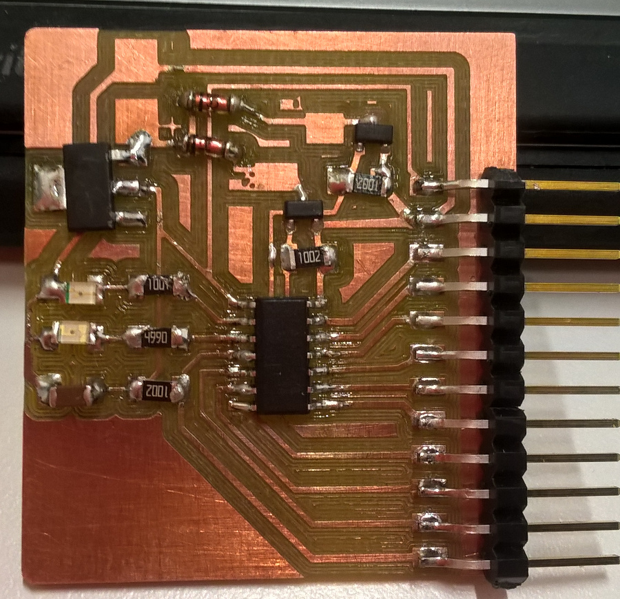
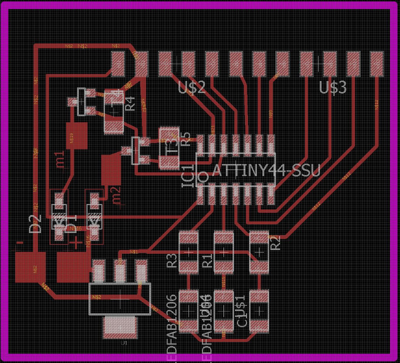
one direction. I made schematics and board plan by Eagle.
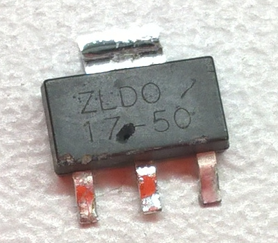
My solution uses 12 V operating voltage from my car. It is
lowered to 5 V for Attiny44 use by regulator ZLDO17-50.
Attiny44 includes 12 I/O pins and it is enough for my application.
Also, I simplified my board by using in-circuit clock.
A motor and a relay are controlled by two N-MOSFETs, type NDS355ANCT.
They have maximum properties of 30 V and 1.7 A. These mosfets are
so tiny, that how they can handle such a voltages and currents?
Further, they are protected by diodes from reverse spike
voltages. This may occur when I stop powering of the motor or any
coil. A reverse voltage, up to several hundred volts and only a
few microseconds, spikes back and kill my mosfet.
I use BAV103 diodes. They reverse voltage is 200 V and
forward continuous current 250 mA. And, they need 10K
pull-down resistors. I made big connector plates to 12V control
wires I could solder there. I drew them directly to board by Rect
drawing tool of Eagle board editor.
All other connections are handled by 1x12 pin header. Other
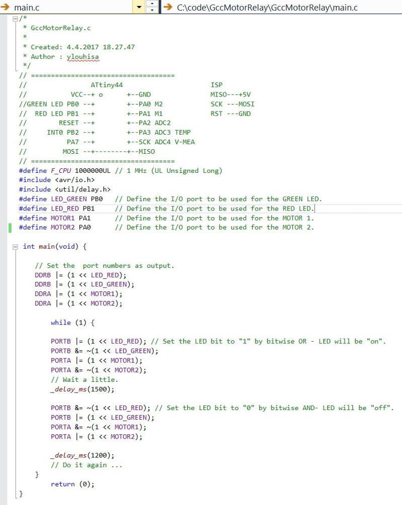
components are familiar from earlier assignments. RED led is
connected to PB1 and GREEN led to PB0. Even, there were familiar
components I needed data sheets to check features. And, the new
components took familiar by reading data sheets.
I could control also speed of motor as described in page:
http://bildr.org/2012/03/rfp30n06le-arduino/. Then, I must connect
motor control to pin PA5, PA6, PA7 or PB2. However, I use pins PA0
and PA1 for these controls. Pin PB2 can be used as interrupt
(INT0) and wake-up purposes.
And, PA2, PA3 or PA7 can be used for analog-to-digital conversion
(ADC) purposes. Hence, they can be used for temperature and
battery voltage measurements. Minimum voltage level could be
detected by certain Zener diode also.
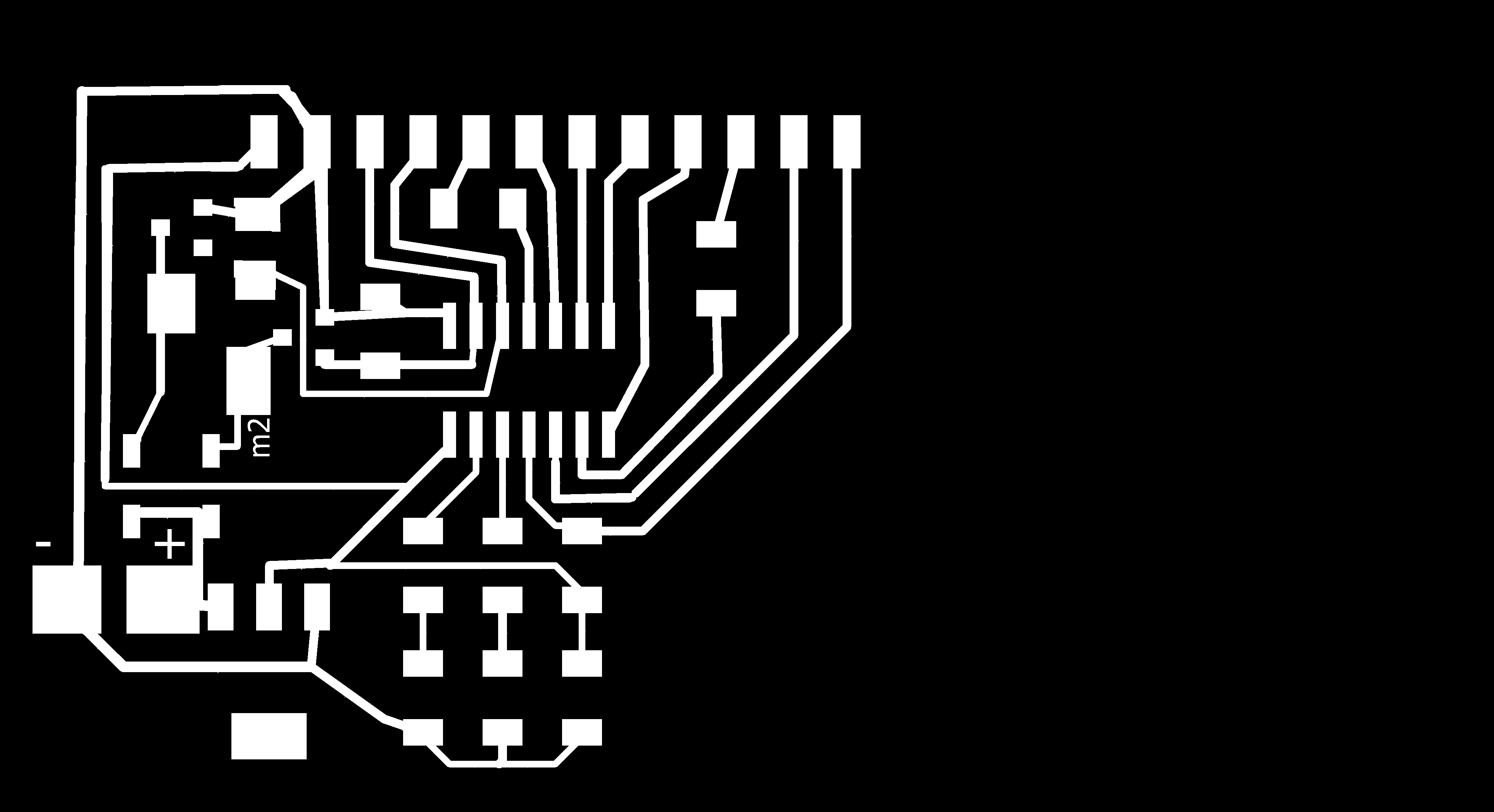
Here, I tested also Antti's idea for PCB milling. I didn't use
Gimp, but exported PNG files directly from Eagle. Purple lines
in the picture represent outlines. I created a new layer and drew
0.8 mm rectangular outlines around my plan, zoomed the window to
fit all and located they to the left side of window.
I exported traces without outlines first, changed the background
color to white and exported then only outlines.
I soldered the microcontroller and mosfets by reflow oven and
other components by hand. Then, I found a mistake, the
microcontroller was upside down. What next? Antti explained that I
can took it out by hot air blower. Some other components dropped
also. I soldered they again, now by hand! Jari helped me a
lot.
Important new components are mosfets and the regulator. I tested
my board by simple program, that blinks the led. Also, I tested
the regulator by 12 V voltage and it powered my board as designed.
I done also a program, which starts and stops the motor and the
relay, as well as blinks the leds similarly.
The fabrication and programming processes were very similar as in
assignments 6 and 8.
Board schematic: FABcamper.sch
Board layout: FABcamper.brd
Png files: FABcamper011.png and FABcamper022.png
Control code: Motorrelay_main.c
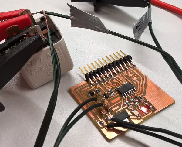
I tested my board and connected it to 12 V power source. It
worked. Then, I connected also a relay from my old car to it. And,
it worked well again. Leds blinked and the relay sounded klik
klik.
 The second minor damage I made was a
small hole in the regulator. I used battery charger, when I tested
my board at home.
The second minor damage I made was a
small hole in the regulator. I used battery charger, when I tested
my board at home. When I worked with Assignment 13, I found error in my
code MotorRelay_main.c. Leds were connected in different order in
my second board as compared to first one. I corrected this to the
code MotorRelay_main.c and documentation here.