Assignment 3. Computer-Controlled Cutting
This weeks assignment was to get to know two kinds of the 2 dimensional Computer Controlled cutting machines, which where Vinyl cutters and Laser cutters
Week 3 checklist:
Viynl Cutter:
I used to have a Silhouette Cameo Vinyl cutter at home for several years, so I am used to it, and I TOTALLY agree with Nail when he said it is tricky to work with Vinyl Cutters as they have too many variables!, especially when using the (Print-&-Cut) feature! it misses the lines for many many times! Lighting environment, blade sharpness, stickiness of the Matt, correct settings... these are some of the variables that I should think about each time I start the machine!
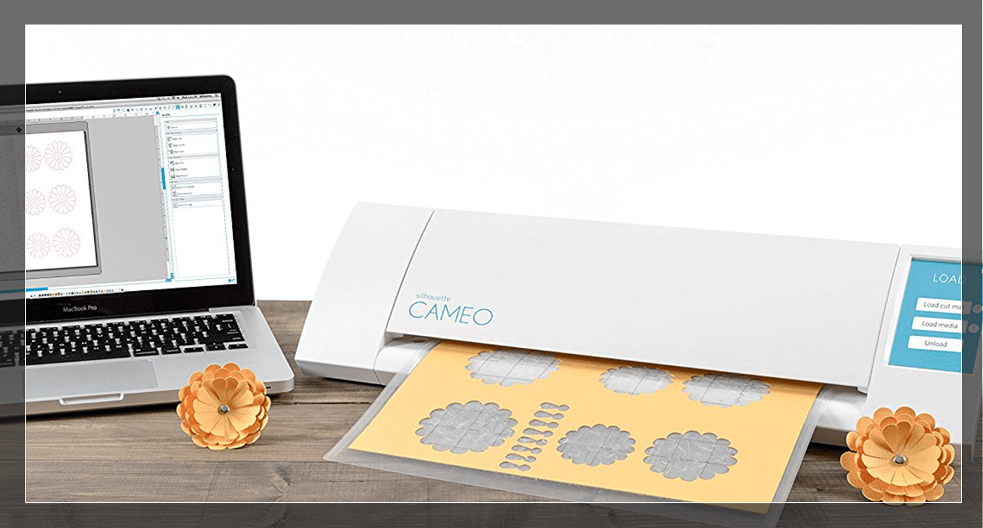
Silhouette Cameo is a very user friendly desktop machine that can be used by almost anyone! it comes with its own software Silhouette Studio that is also very easy to use when the user gets to know the basics they can handle it very fast... Silhouette America has built a great community for its users, and it has a great collection of tutorials all over the internet!
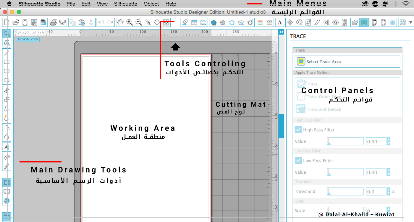
All the tools in the software are stright-forward and easy to use,, and this is my mostly used tools..
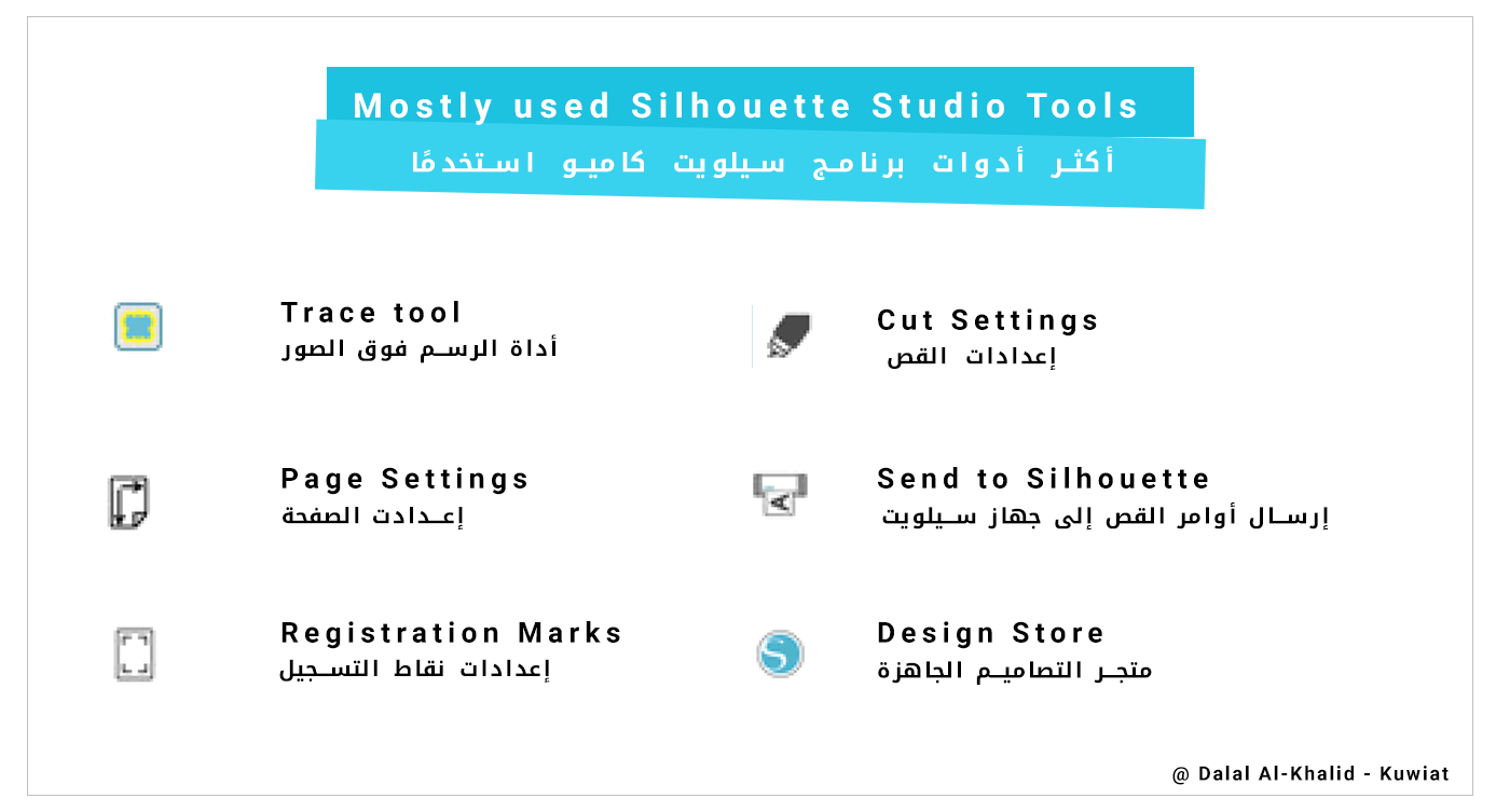
• Trace tool: is the tool I use to trace around my PNG designs.
• Page settings: this is where I change the size of the page and matt.
• Registartion Marks: used in Print & Cut to cut round the designs.
• Cut Settings: Change the settings accroding to different materials
• Send to Silhouette:send the cut command to the machine
• Design Store: where I can find many inspiration, and ready-made designs.
Cameo Supports both SVG & PNG files, both are easy to use..
Adobe illustrator
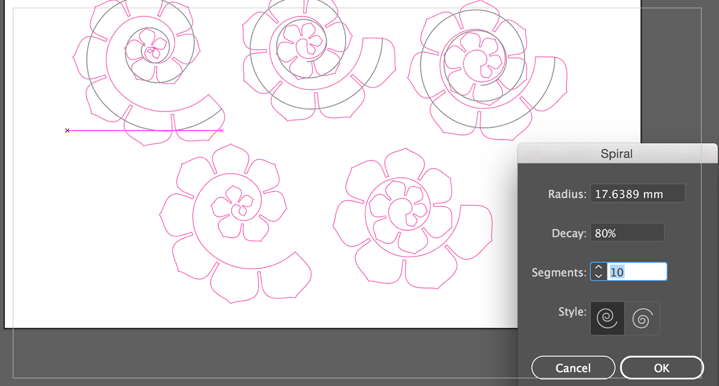
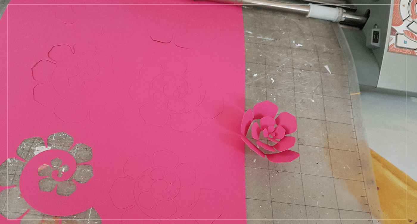
I started to design my Flower in Adobe illustrator, and after couple of experiments I have got closer to the design I want which is leafs spiral that would create a flower once I rolled it,,
I have created a leaf shape, then copy it to a smaller size, after that I have blended the two shapes to create the sizes in between,, after that I have correct the alignment and the spacing between, then I added a thin strip to the bottom area of the leafs and merge it with the shapes,, and finally I have taken that shpe and covert it to a brush so that I would be able to use it with the spiral tool ..
The following step was to create the perfect Spiral, and I have experimented with different segments until I was happy with two of them.. after that, I have exported the image as PNG, 300 DPI, transperant background.
Silhouette Studio
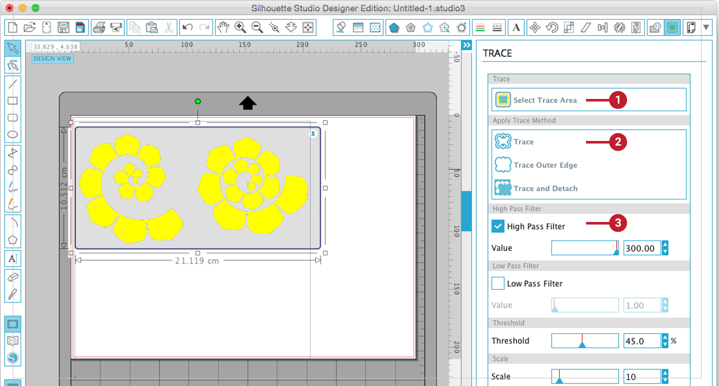
1. I have started by drag and drop my PNG file in Silhouette Studio and traced around it using the Trace tool the select the whole image by press & pull the mouse button.
2.Apply Trace method.
3. then slide the High press filter to its maxiumum values, or until the whole image turns yellow.
4. for the cut settings, I have used the defult Cardstock settings.
5. Change the blade size in the machine.
6. Load the mat with cardstock attached, then CUT!
It was a great experience to discover how to design that kind of designs, and the best part is it almost WORKED : ).
[ Source File - AI File ]
![[ Source File - PNG File ]](src/week3.png)
[ Source File - PNG File ]
[ Source File - STUDIO3 File ]
Laser Cutter:
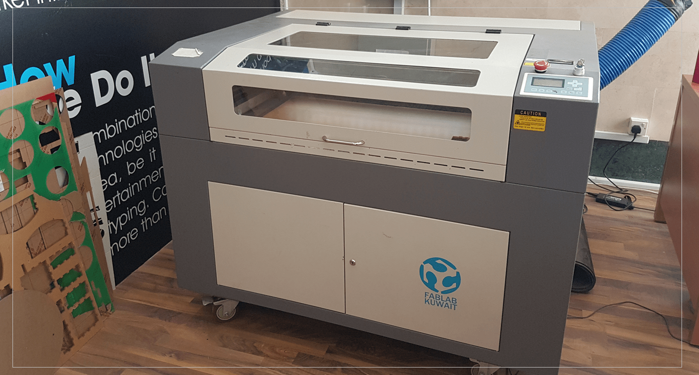
Laser cutter is one of the best machines that I LOVE to use,, in our lab we have CO2 Laser cutter, and uses lasercut 5.3 software,,
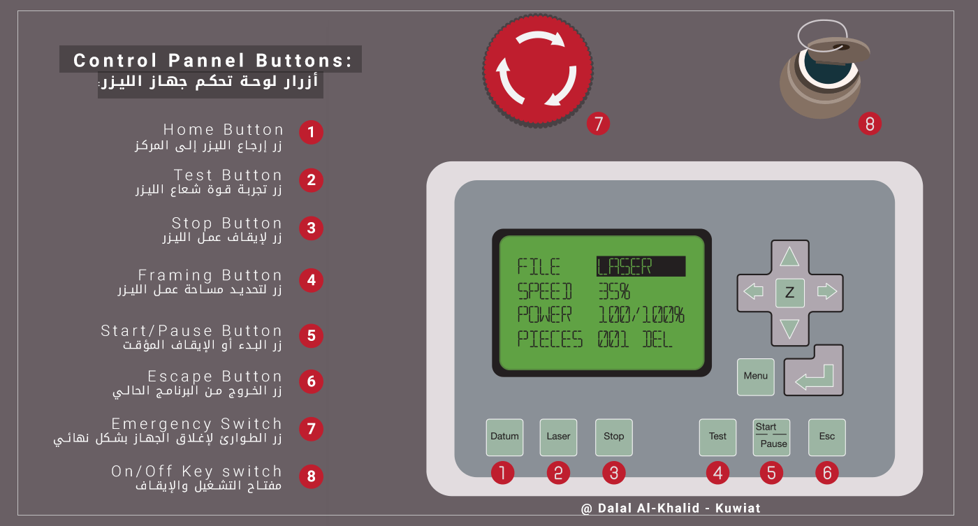
The control pancel is stright-forward, and easy to understand, there are 6 main buttons, and a screen, as well as main Switch key, and Emergency stop ..
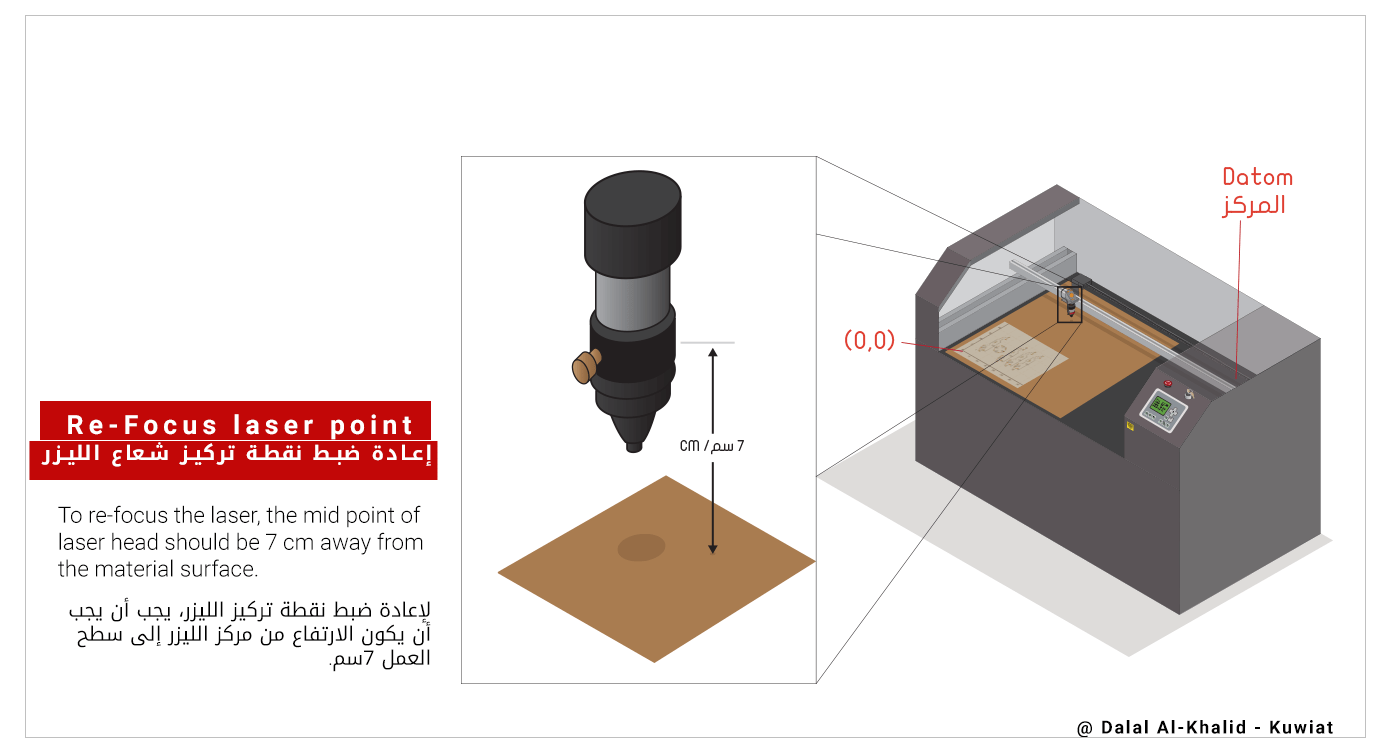
Re-focusing the laser beam point is one of the most important aspects related to laser cutting,, because when the surface of the material is very near to the laser beam, the cut line will not be sharp, and if it was too far, the machine will need more power to cut through the material,, in our machine the mid-point of the laser head shoud be about 7 cm above the surface in order to get the perfect cut..
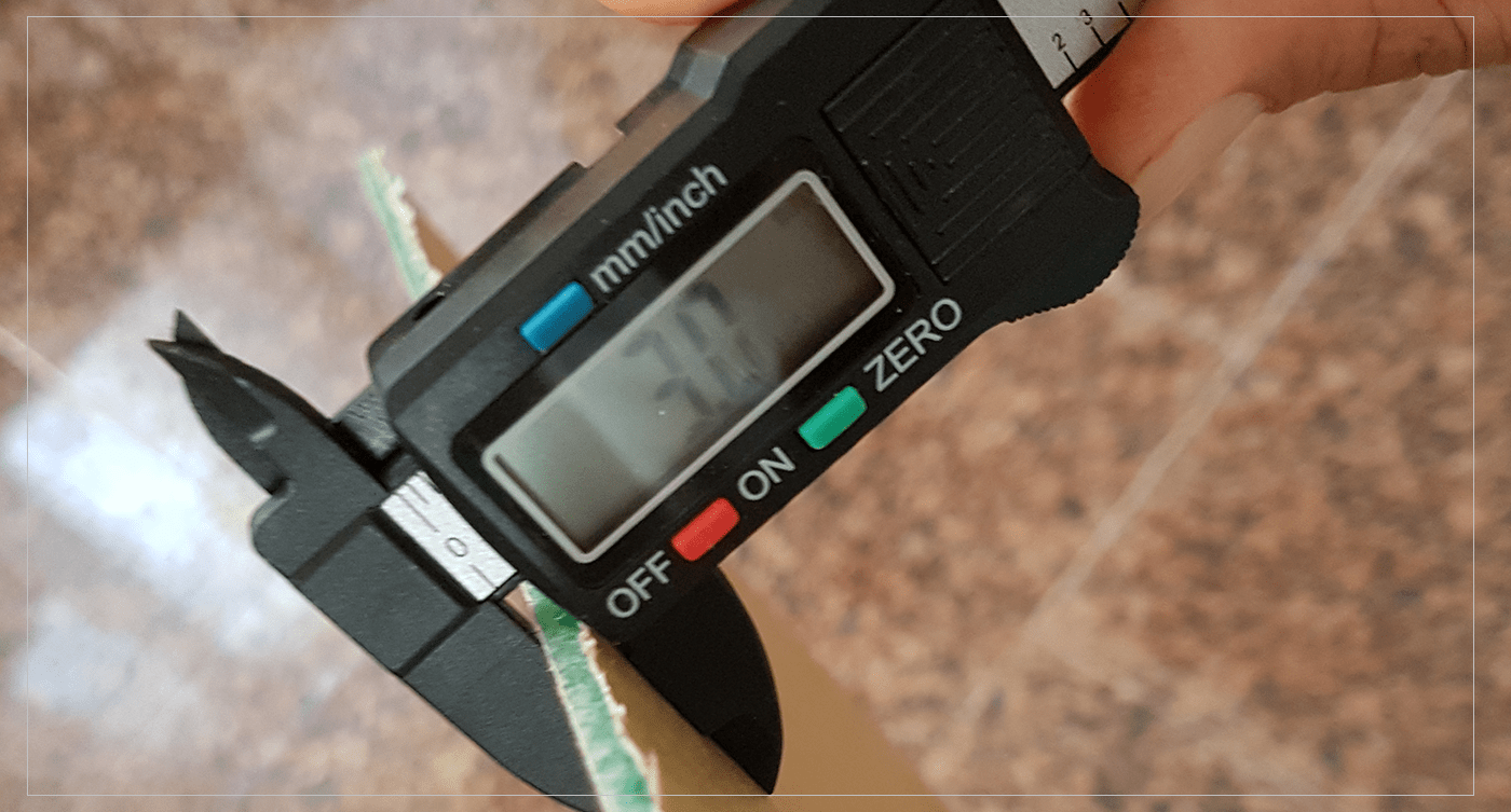
I have basic knowledge about the machine, as I have used it couple of times previosuly, but I need to refresh my memory..I have started by measuring the material I am going to use, which is 3mm Acrylic..
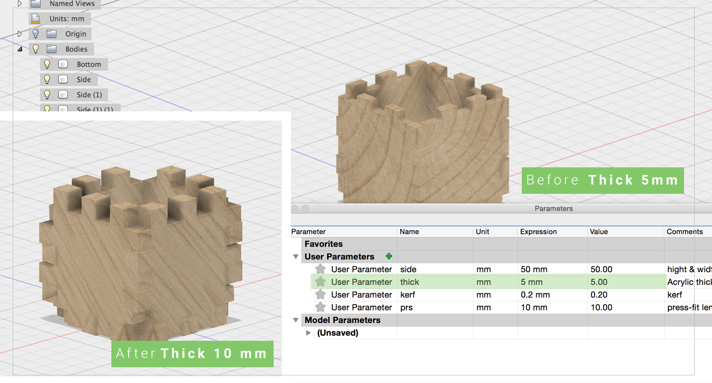
Parametric Design:
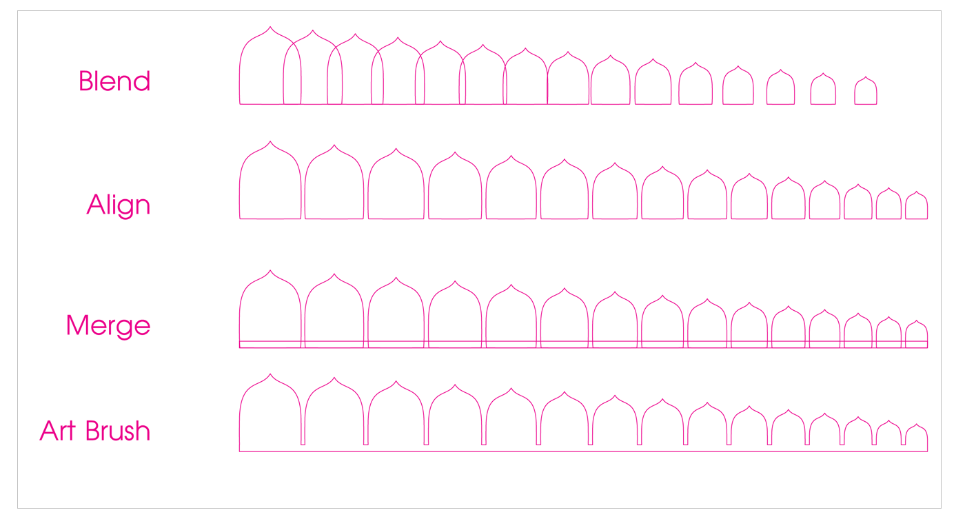
As far as I know, Adobe illustartor does not have many (Parametric Design) rules,, there are couple of tools that uses couple of algorithims ( like spirals, Blend-distance ..), but these have their own specific uses, and I can not use them for all my designs! So I made my own guides that I will be using in designing the sample test ..
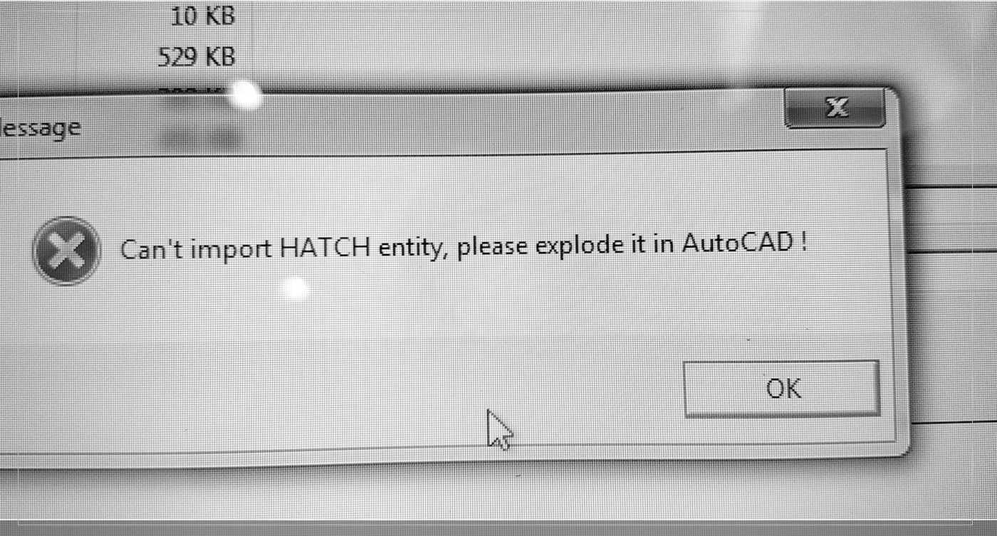
So I started by designing a simple shape to test the interlock concept using Adobe illustrator, then I saved it as DXF .. I was making the shapes as I used to create them for designs ( Only fills) so when I took the file to laser cutter software I received a HATCH ERROR! at first I did have any idea what was the problem,, but after consulting our local instructors I figured out that DXF files only reads the Strokes not Fills! So I changed the settings and went back to the software, and it worked fine this time ..
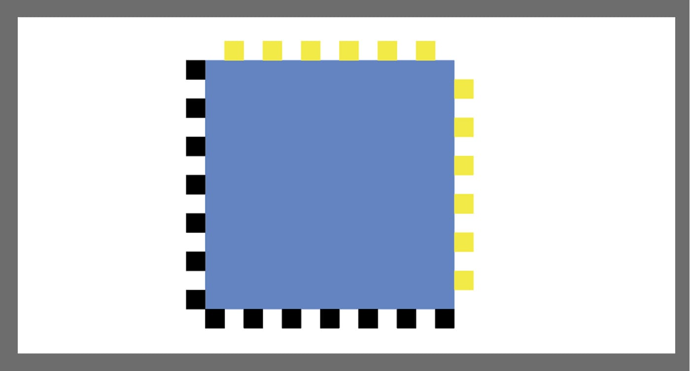
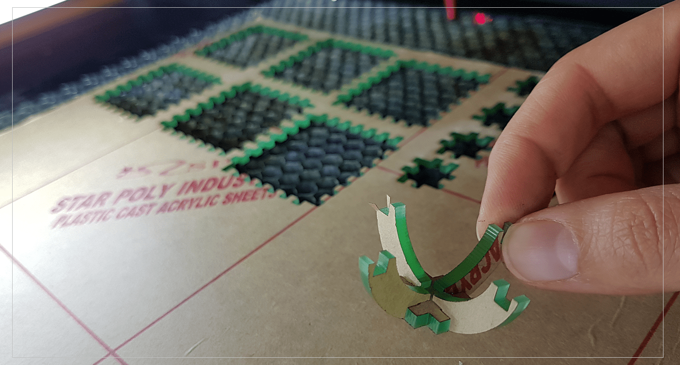
 The design I made at first was very simple,, a square that have 3mm square teeth around it,, ( the teeth and the cuts were both 3mm).. but when I have cut them there were very loose! After searching about the problem, I discovered that the problem was the because of the Kerf! Kerf
is the burning part of the material which will result in increasing the area of the slot by about 0.2mm.
The design I made at first was very simple,, a square that have 3mm square teeth around it,, ( the teeth and the cuts were both 3mm).. but when I have cut them there were very loose! After searching about the problem, I discovered that the problem was the because of the Kerf! Kerf
is the burning part of the material which will result in increasing the area of the slot by about 0.2mm.
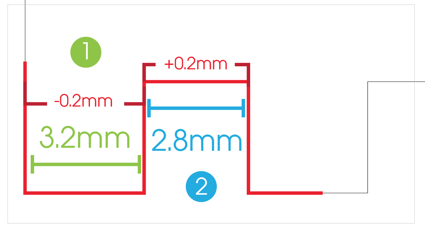
 I did many experiments until I figured the "Golden Rule",, which is simply any teeth should have extra 0.2mm and the width of holes should be reduced by 0.2mm..
To explain what is happening,, The laser usually burns about 0.1mm from the line of the cut so when my square is 3 mm it would burn 0.1 mm from both sides which would result in 2.8mm! on the other hand the holes would get extra 0.1 from each side because it was taken from the nearby square! so it would become 3.2mm ..
To fix that problem,, add extra 0.2 to the teeth, and reduce 0.2 from the holes..
And It worked Perfectly : )
[ Source File - DXF File ]
[ Source File - PDF File ]
Parametric Design Part2- Fusion360:
After completing my project using Adobe illustartor, I have been experimenting with Paramertic tools in Fusion 360,, and here is the process:
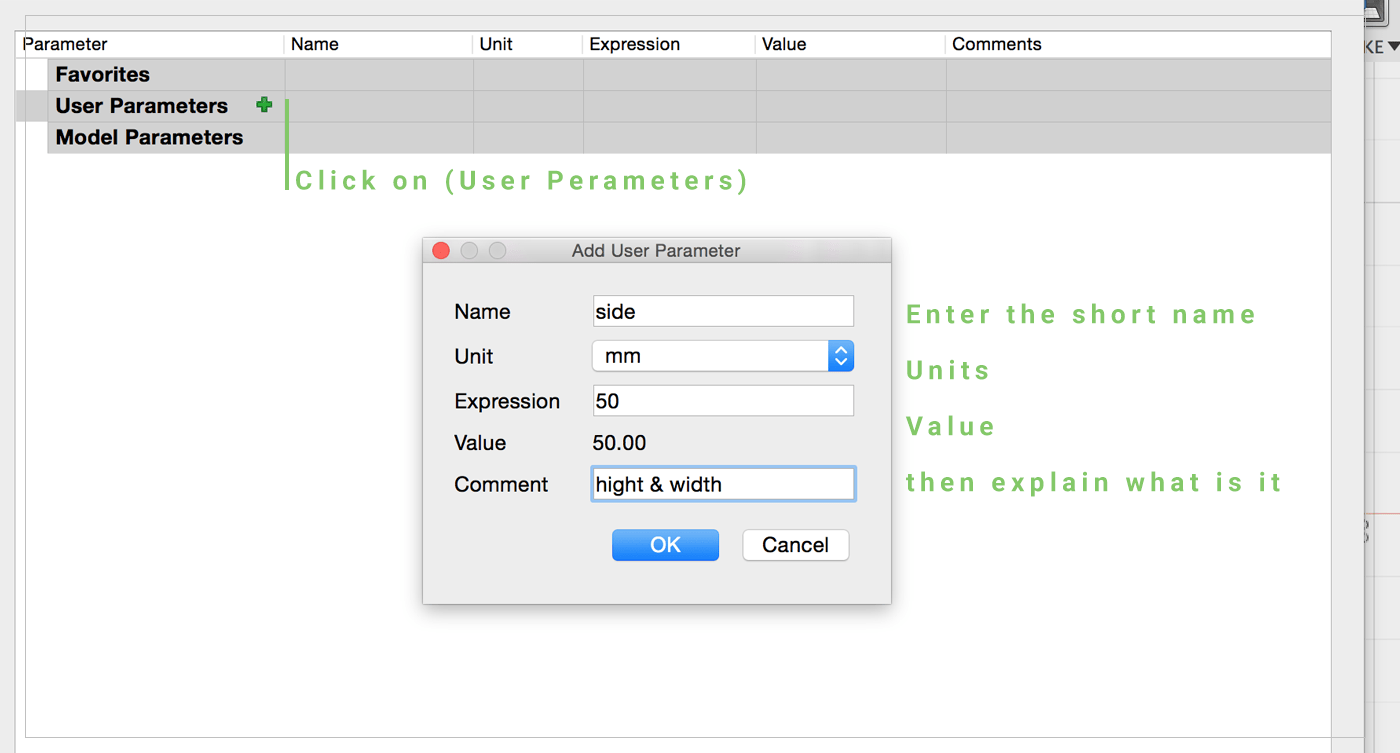
I have starterd my design by going to Modify > Change Parameter, to define my designs peremetic rules..
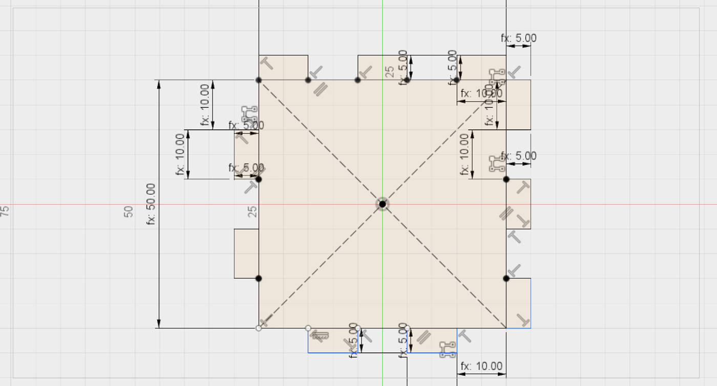
 Then I have draw a square using the parametiric rules I have defined previouly,then draw 4 lines for the press- fit slot, after that use the Rectangular pattern,to copy the slots all along the sides.
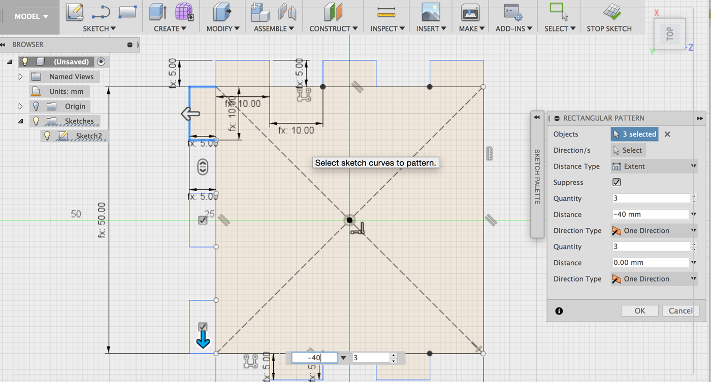 After that I used the Contraitns from sketch palete to keep the lines attached to each others
 Lastly, I went to Change Parameter again and tested the rules, and it worked fine : )..
[ Source File - F3D File ]
[ Source File - DXF File ]
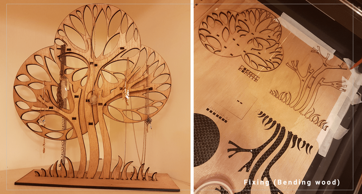
Necklace Stand - Press Fit
In order to put my knowladge into work,, I have designed a simple Necklaces Stand,, I have made the dxf file in Adobe Illustrator, and then preview it on Fusion 360,, then cut it using the laser cutter..
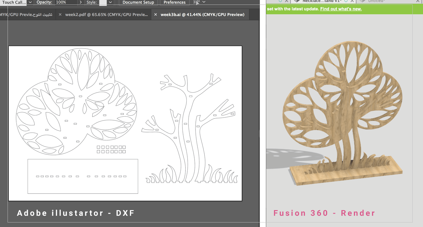 My design consists of two layers to look nicer,, but I faced a problem with the attaching the two layers together, so I decided to cut a hole in both layers, the insert a third peice to attach them together.. and it works perfectly,,