Assignment 4. Electronics Production
Electronics is the first NEW subject I will be learning in this course, I have been soldering some electronics when I need to do so, but I had NEVER made my own PCB or solder such tiny pieces!! so lets get learning ..
Week 4 checklist:
Eagle Cad:
I have started this week process by choosing the best suited PCB Design from the links provided in the Assignment section for this week.. and I have choose David design because it best suited the tools and elecronics we have on the lab,,
So I have started buy downloading Eagle on my Mac laptop and the fabisp.brd from David's Page to start familiarizing myself with the PCB making world,,
P.S. David's Page from Assignment section is not working NOW, I have found another link (above) but it might be different virsion from the one I have used.
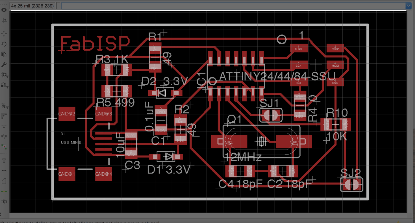
[ Source File - DAVID ISP BRD File ]
At First the drawing was VERY SCARY! Black background with many numbers and letters that I could not recognize any of them! but after getting some help form our local instructors I started to connect the dots and understand the concept of the SMD,, as I have basic knowledge in electronics (the regular size) I have started to better understand the image.. At this stange we were asked to familirize our ourselvs with Milling process, so the first step was to creat Gerber file..
What is Gereber file?
Gerber is a standard electronics industry file format used to communicate design information to manufacturing for many types of printed circuit boards.[Source]
Create a Gerber File Using Eagle on Mac OSX:
Being the only student who uses MAC OSX on my lab is challenging, because I have to figure many stuff by myself, like the problem that accrue today when I have tried to create a Gerber file using Eagle, all the tutorials I have found online were for Windows! and when I follow through, I reach a point were my window on MAC is different than the window on Windows! so I have moved to a windows computer to complete the project, with intention to find a way to do it directly from my Mac..
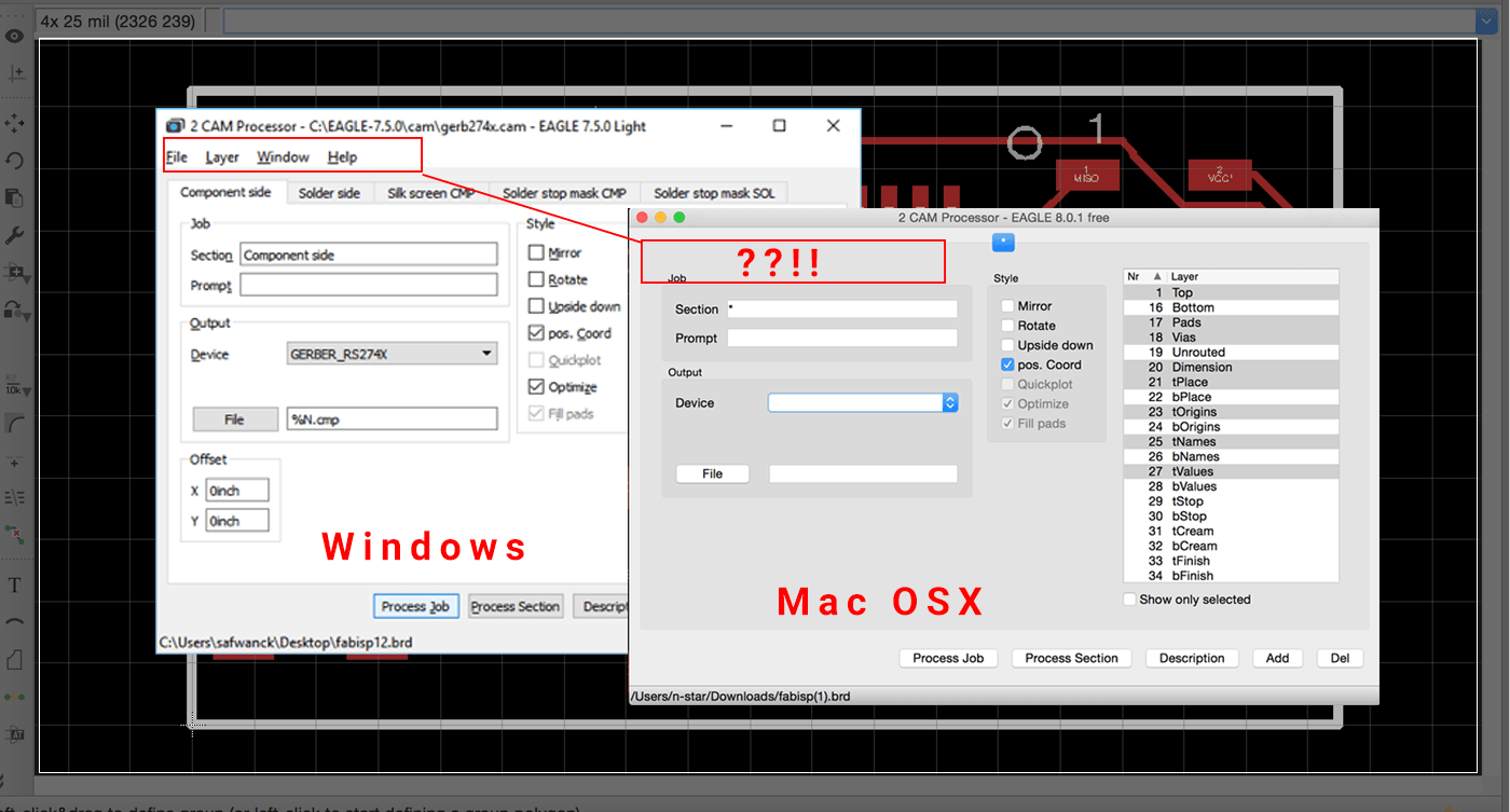 Later that night, I found the Solution :) .. here is how to make a grabber file using Eagle on Mac OSX ..
cirQWizard PCB Milling Machine:
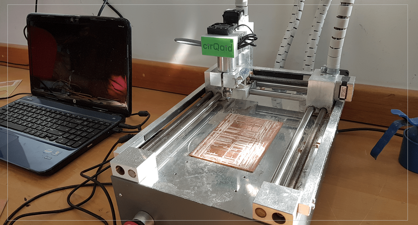
After creating the Grabber File, I have moved to our cirQWizard PCB Milling machine to start the Milling process ..
First, I have connected the Milling machine to the laptop using USB Cable, after switching the machine on, I have opened the Milling Software we are using in the lab which is cirQWizard, its Fairley easy to use and have a similar process to the Lasercutter machine ( different colors can have different settings)
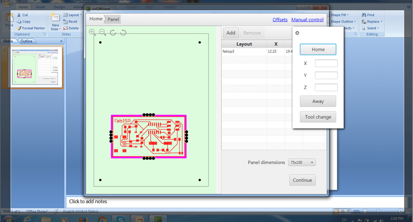 I have started by bringing the end mill to its Home which is the (0,0) point, by going to Manual Control on the top right section, then choose Home, so I can do two things:
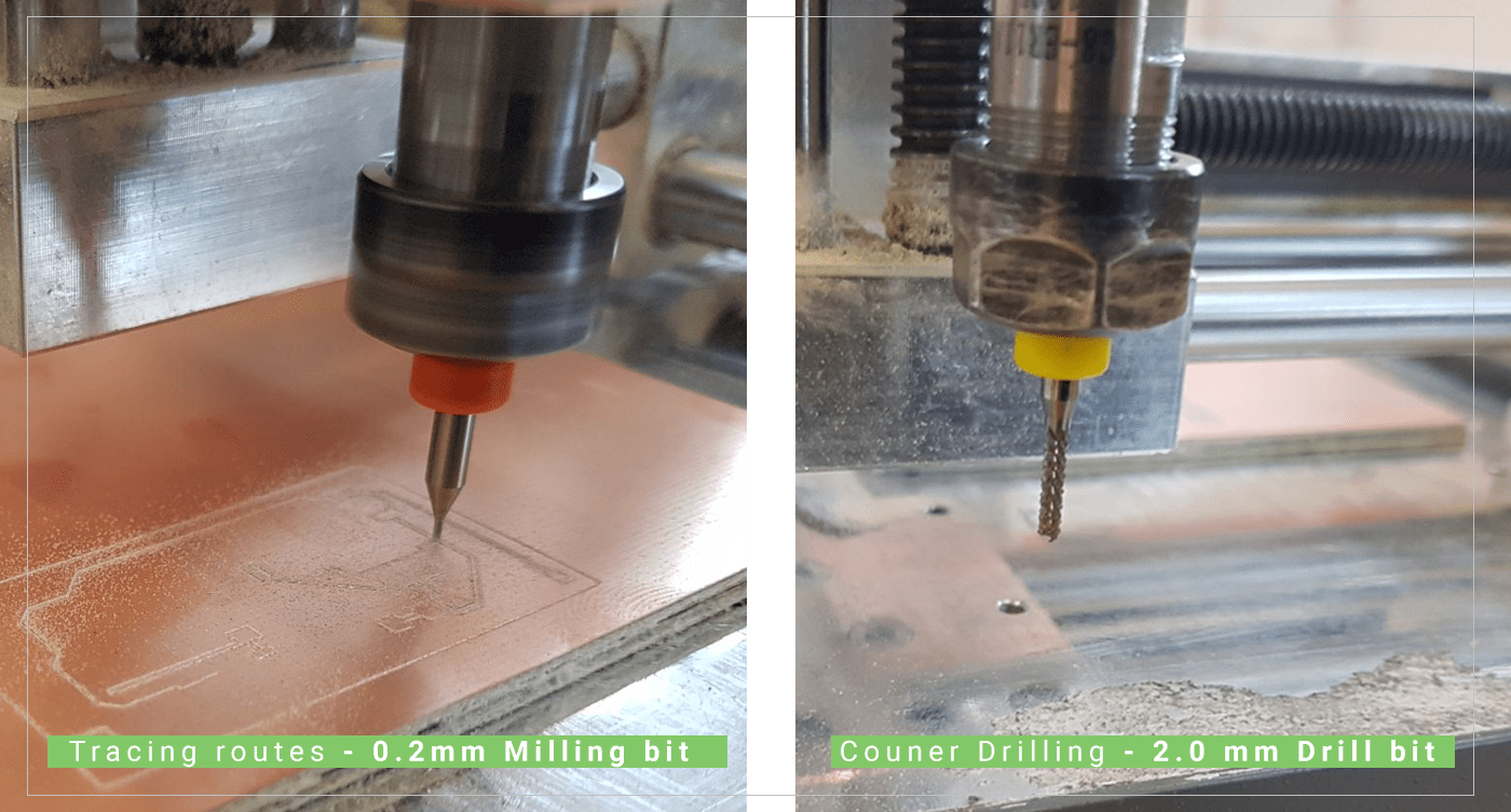
1. Change the end mill to the milling tip (0.2mm).
2. Test the milling on all sides of the board to check if the board is leveled correctly and will engrave well along the whole board.
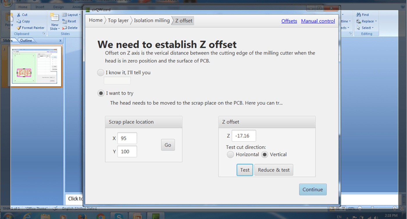
 After that I have made couple of tests to check for the right depth for the Z axis, and it was (-17.16), to test I have to pick about 4 different locations on different spots on the board ( eg. Top right, top left, bottom right, bottom left) and make a test .. if the line was deep enough on one point I have to move to the next point to check,, if on one of the point the line was shallow, I will to press on Reduce & Test so that the machine will reduce the Z axis in an increments of 0.02 each time..
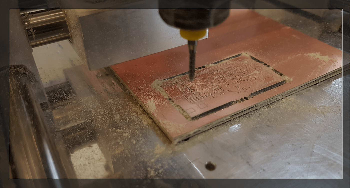
 After getting my number right, I have press on Continue Button at the bottom right area of the window, to proceed to the milling process, the software will ask me to change the end mill to (0.2) to start making the path for the board,, after completing the milling process for the main traces, the software will ask again to change the end mill to the counter drilling bit (drill- 2.0 mm) so that it would drill the holes, then cut all around the board.
 We have cleaned the mess by vacuuming all around the board, and use G-22 dry contact cleaner to clean the board,
Soldering Process:
I have started to solder using my own regular Soldering iron, but it was VERY hard to catch the tiny components, and it has fixed temperature, which I think was not hot enough for the SMD process,,
 so I went back to the lab to use the SMD Soldering Station.
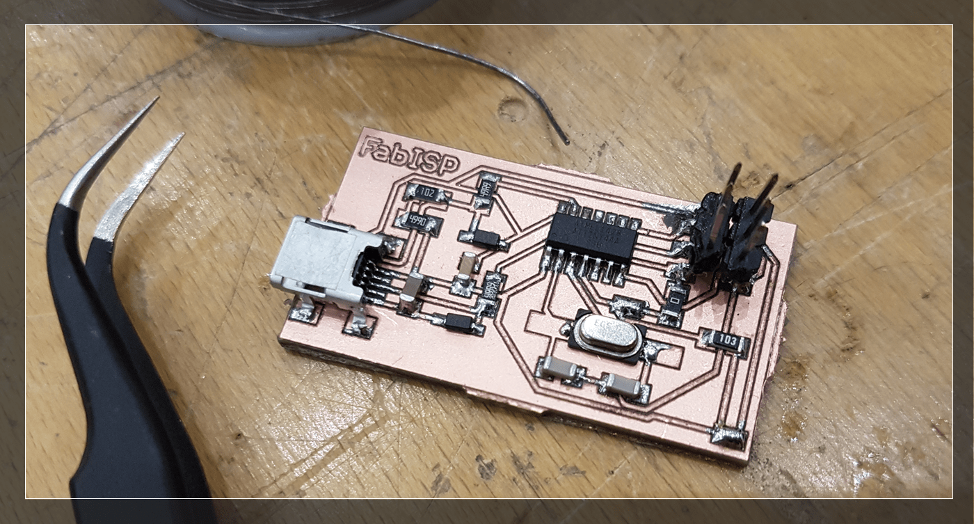
Because I have messed up with the solder,, I decided to start all-over and mill a new board to start clean, the process was not easy this time also, but it was easier than my first attempt.. I did better this time, and my connection points are small shiny : )
Soldering Problems
Couple of problems I have faced while soldering:
1. Tiny components were hard to handle and sometimes it was even hard to see! so I have place one component at a time, and try to solder it before placing the second component.
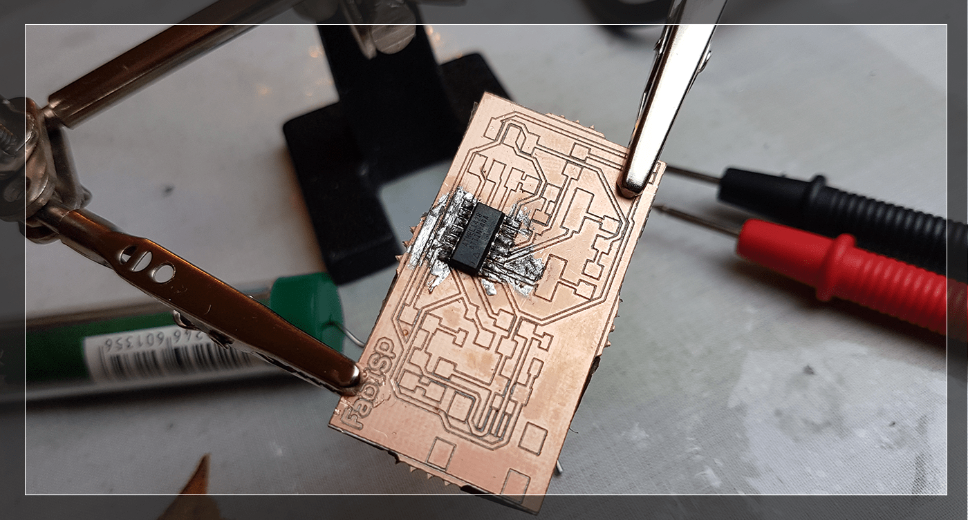
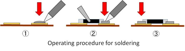
2. Soldering the capacitors was the HARDEST of all! they were big and I struggled a lot to attach it, so our local instructor taught me an easy way for this problem which is by putting some solder on the board first them melt it again with the capacitor on top of it ( see image bellow)
Programing the Board:
To programe My ISP, I have followed the following steps:
1. Download and Install Crosspack AVR.
2. Download (FabISP Firmware for MacOS 10.8.2.):
3. Unzip the File on Disktop.
4. Right click on the file choose (New Terminal at folder).
Editing the Makefile
Open the Makefile with TextEdit, the edit the following:
#AVRDUDE = avrdude -c usbtiny -p $(DEVICE) # edit this line for your programmer
AVRDUDE = avrdude -c avrisp2 -P usb -p $(DEVICE) # edit this line for your programmer
I am using the USBtiny programmer so I have to do the following:
- Remove the "#" in front of the line with "usbtiny" in it
- Add a "#" to beginning the line with the "avrisp2" in it to comment it out.
- save the Makefile
Program the FabISP
Navigate to the directory where you saved the FabISP firmware. If you followed the instructions above, this will be the desktop.
- Right click on the ISP folder then choose (New Terminal at folder).
- To complie the firmware write:
make clean then
make hex
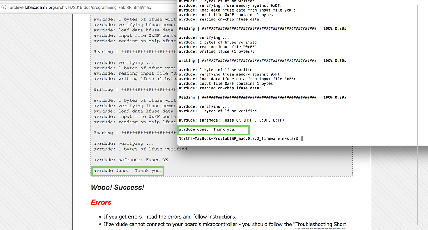
- To set the fuses so the board will use the external clock (crystal) wite: make fuse
- To program the board to be an ISP write: make program
- And it was Completed Successfully : ) .
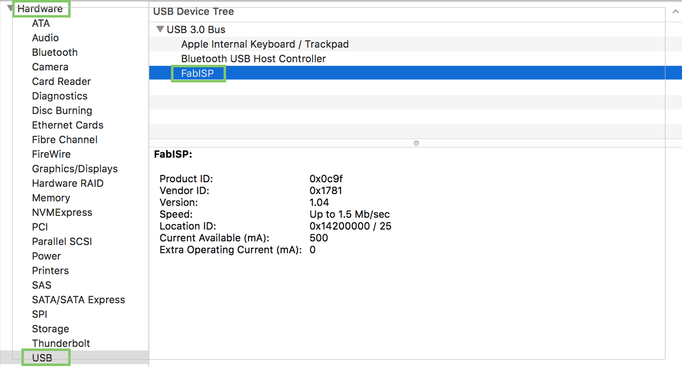
 To check if my ISP is working correctly.. go to:
1. Click on the apple menu in the main toolbar.
2. Go to About this Mac.
3. Click on System Report.
4. Under Hardware click USB.
5. If you see the FabISP under USB Device Tree, then you have successfully Programed you ISP!.
Previous Week Home Next Week