Assignment 13. Input Devices
For this week I will be control an LED by using a CDS/LDR ..
Week 13 checklist:
Input devices
An Input device is any peripheral that converts the real-world properties (light, touch, sound… etc.) into data that a microcontroller can process. An input sensor will measures a specific property data and sends a signal to output peripherals to be executed..
Examples of Input devices:
There are many Input devices avilable on the market,, I will mention the most device I might use:
1. Buttons and Switches:there are many types of buttons and switches, but all of them share the same concept, when the button/switch is pressed a signal is sent to the microcontroller.
2. LDR: Light Dependent Resistor, Photoresistor, or CDS, is a resistor which has a resistance that varies depending of the light intensity.
3. IR Sensors: Infrared is a form of light that can not be seen with human eyes, but can sometimes be sensed on the skin as heat.
4. Ultrasonic sensors: Ultrasound is sound waves with frequencies higher than the upper audible limit of human hearing..
5. Microphone, Temprture sensor, color sensor, variable resistors... etc
Electronics Design
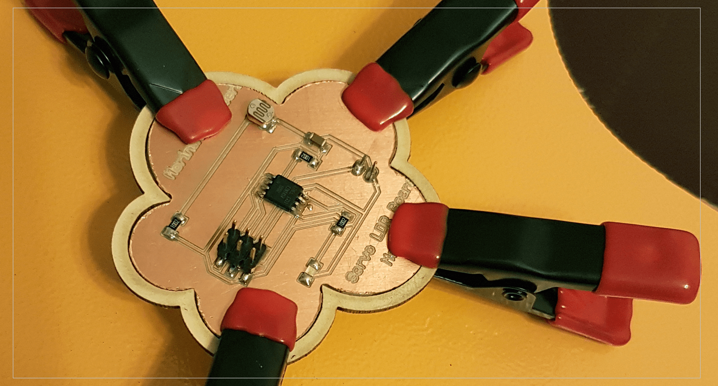
For this week I will be control an LED by using a CDS/LDR ..
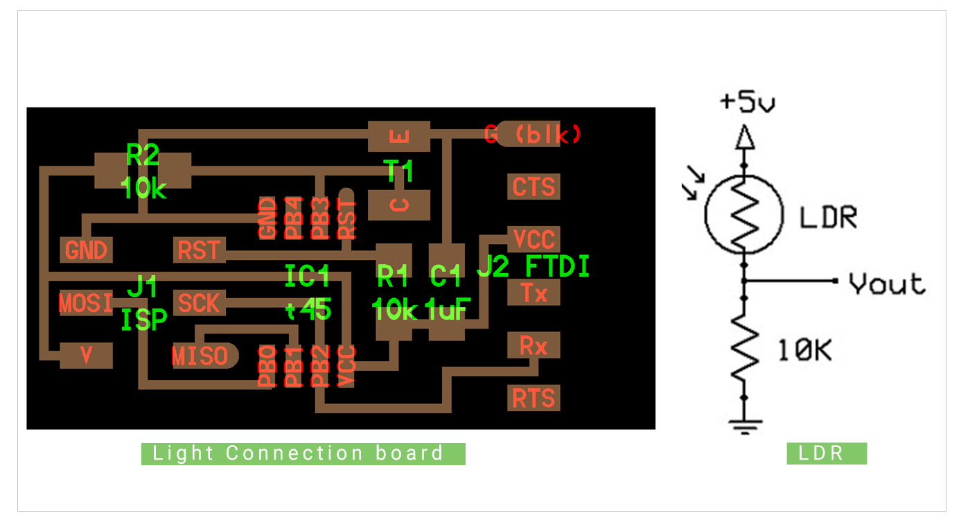
I used the light board from the references of this weeks to make my board as well as an LDR connection daigram, I was planning to add a servo, but I have discoverd a mistake I have made after milling the board, which is I have used 2 pins-head insted of 3! So I decided not to use the servo for this project, but I will practice with the board later to add it to my Final project ..
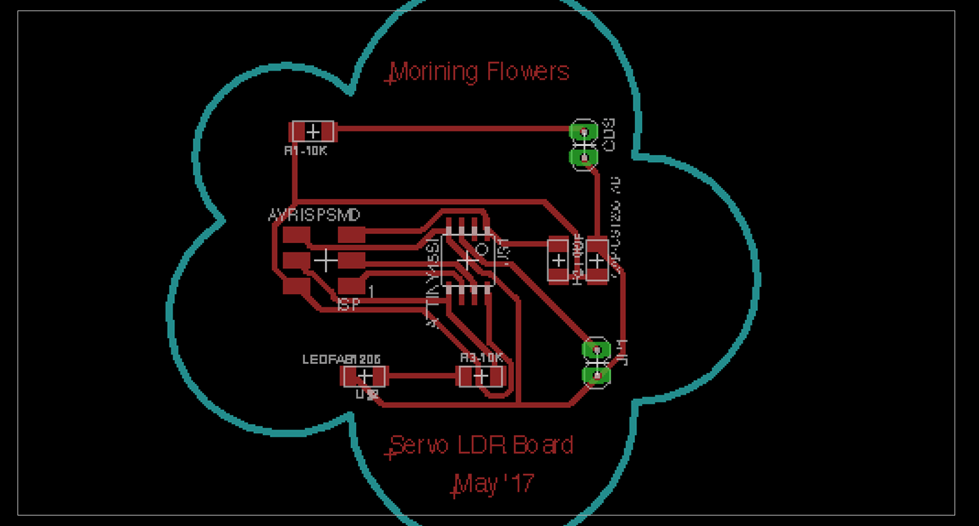 After that I have created the Grabber files, and mill the borad using our PCB Milling machine..
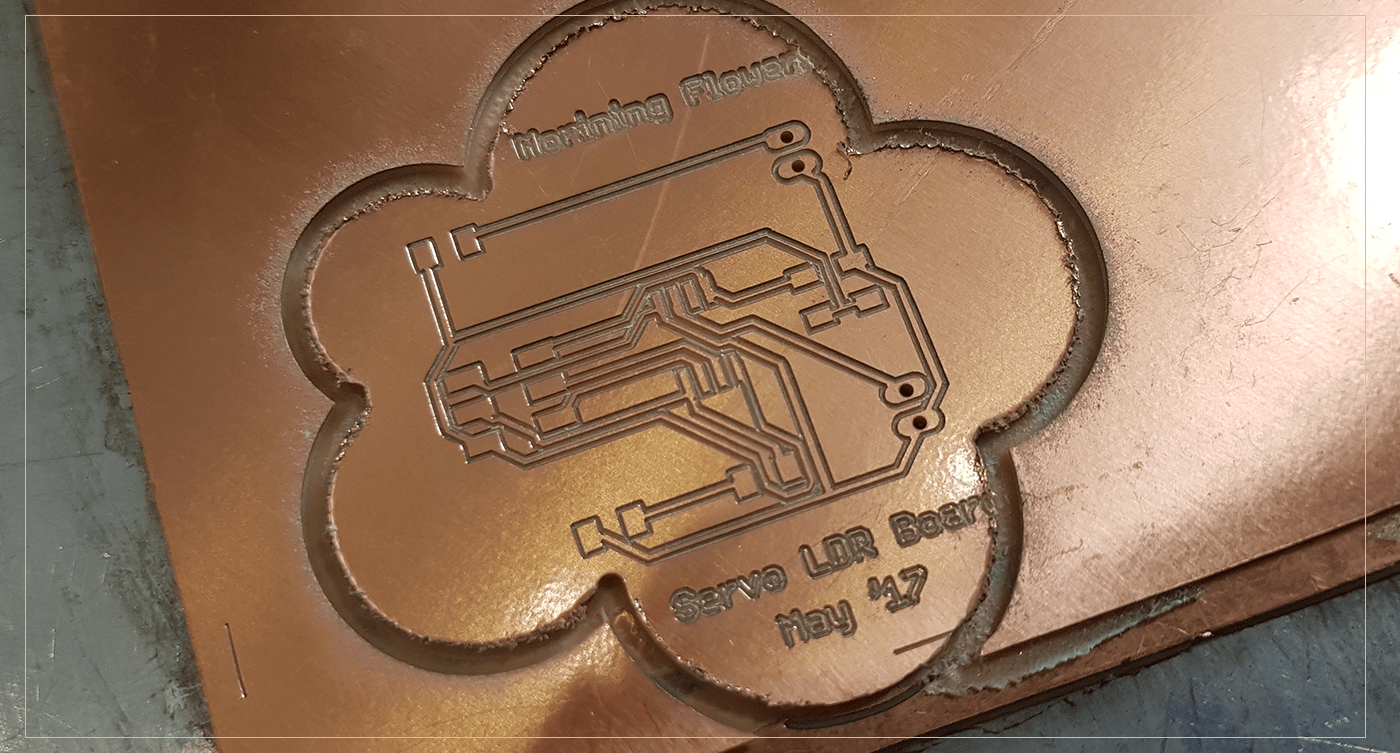 I used a new dilling bit to cut the boards frome,, and it was very harsh! The board's sides were very rough! .. I have tried to sand them with sanding paper, but I was afraid to scratch the board's surface becase of the curves,, So I decided to make a housing for my borad and it would look even neater : ) .. so I did design a frame and a bottom plate to hold the board, then cut them using Laser cutter.. then using glue to attach the frame to the bottom board.. it was a GREAT Soultion : )
Programming the Board:
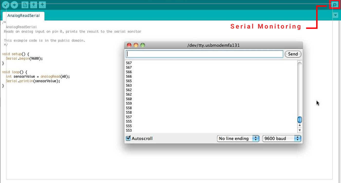
Serial Comunication:
The first step was to test my LDR by conncting it to Arduino Uno Board, then by using a simple code I could make sure that the LDR is working and at the same time get the readings of the around environment ..
void setup() {

  Serial.begin(9600);
}

void loop() {
  int sensorValue = analogRead(A0);
  Serial.println(sensorValue);
I have searched for a LDR code on the web, then modify it to fit my project..
here is the code:
int sensorPin = 3;

int sensorValue = 0;

void setup() {
  pinMode(0, OUTPUT);
}

void loop() {
  sensorValue = analogRead(sensorPin);

  if(sensorValue < 700)
  {
    digitalWrite(4,HIGH);
  }

  else digitalWrite(0,LOW); //turn LED OFF


  delay(100);
}
[ Source File - BRD File ]
[ Source File - SCH File ]
Previous Week Home Next Week