Assignment 6. Electronics Design
In this week lesson, I will be demonstration how did I make my first PCB Board using Eagle Cad, and milling it using CirQoid milling machine..
Week 6 checklist:
How to design Your First PCB:
The BEST method to learn a new subject is "Learning by donning!" which is the main philosophy in Fab Academy,, So we started by replicating an existing Hello World board, then I will add a switch and LED to experiment with improving that board.
Gathering information:
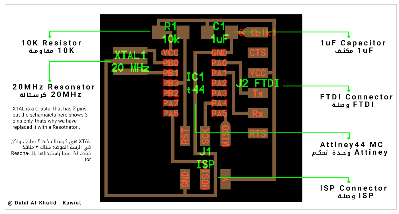
The First step is to figure out what are the components needed to build this board ..
 After that, I have downloaded the Fab library
for Eagle cad, which contains all the needed components for this board..
After that, I have downloaded the Fab library
for Eagle cad, which contains all the needed components for this board..
Creating a project in Eagle Cad:
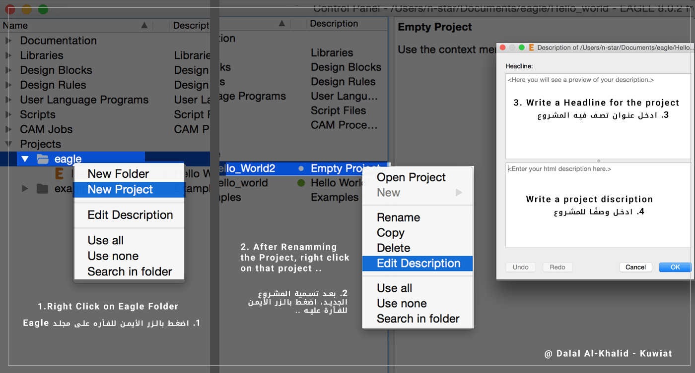
(1) Click on Eagle Cad icon, then:
1. Right-click on Eagle folder, then choose New Project.
2. Rename the new Project, then right click on it and choose Edit Description.
3. Add a Headline, and discretion for the project for future uses.
4. Right-click on my project again and choose New> Schematic.
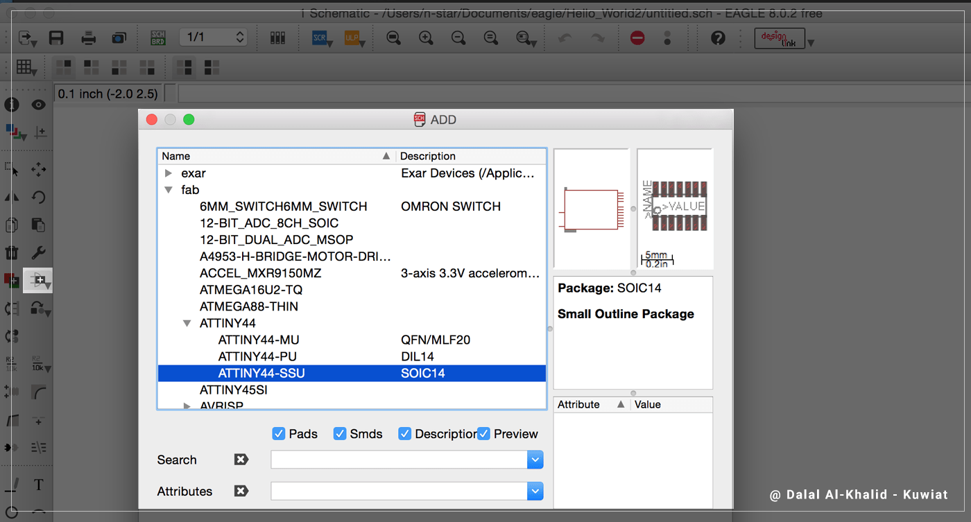
 (2) Click on (Add) on the Toolbar to add the components to the schematics, I have chooseثى the components that match the footprints of the components on the original Hello World board, with the images on the library, All the following components are on Fab folder:
• ATTINY44> ATTINY44-SSU
• AVRISP>AVRISPSMD
• CAP-US>CAP-US1206FAB
• FTDI-SMD-HEADER
• RES-US>RES-US1206FAB
• RESONATOR
 These are the main tools I have used in Eagle:
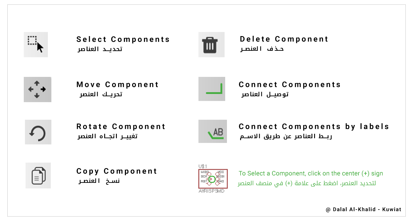 important: in order to choose any component, you will have to click on the (+) on the component.
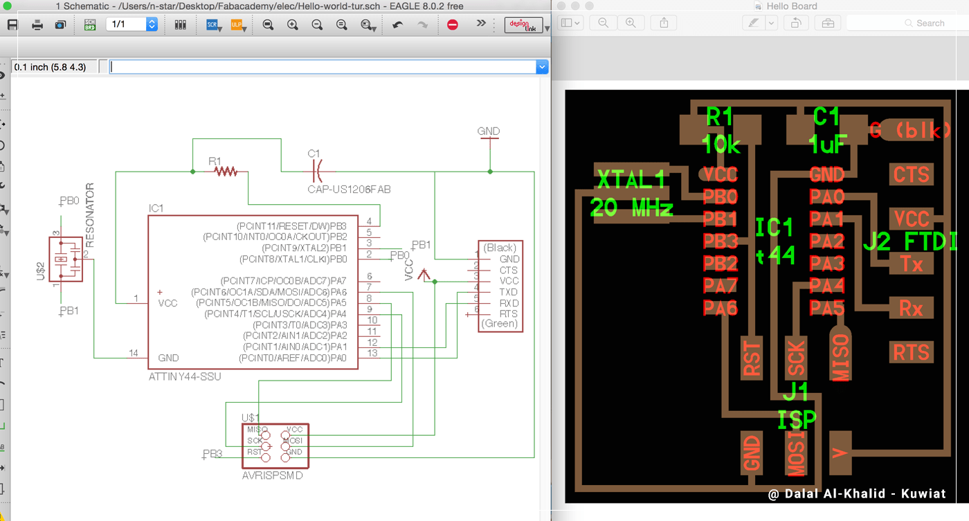
(3) The following step will be to connect the components following the Hello Board schematics, and I did this using two methods:
• Net tool: This tool is used to make real line connection between the components.
>>To use this method: click on the Net tool, then click on pin A, then pin B, and they will be connected with a green line.
• Label tool: Connect the components with shared name.
>>To use this method: click on the Net tool, then click on pin A and drag a short line then press (ESC) once, do the same with pin B, then press (ESC) twice to exit the Net tool. Now choose the Label tool and click on the short line of Pin A, and Pin B, a default name will appear (N$1, N$2 ..) Then type on the top white rectangle area (Name) and click on the (+) sings on the labels, rename both pins with the same name (eg. GND), when renaming the second label, a pop-up window will appear with the following message (Connect N$2 and GND?), click Yes, and the pins will be connected on the board.
important: Lines can overlap on Schematics.
Adding Extra components:
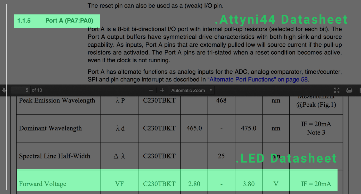
I have added a 6mm switch and SMD LED for my board,, but first I have to look at the Attiny44 datasheet to check for the ports that allow Inputs and outputs, then look for the LED datasheet to check for the Forward Voltage and Current which will be used to determine the value of the resistor needed for the LED using Ohms Low or use the LED calculator website,
After that I have added the following components to my schematics:
• 6MM_SWITCH6MM_SWITCH ( Connect one leg to GND, and the Opposite one to a pin on Attiny44)
• LEDFAB1206 ( Connect one side to GND, and the other to 102K resistor, then from the resistor to a pin on Attiny44 )
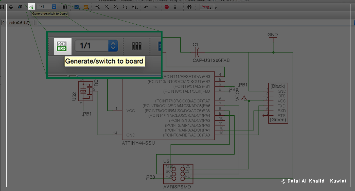
Making the Board:
Click on (SCH/BRD) icon on top of the window to switch to Board mode, Save the schematics so that you will be able to make the board.
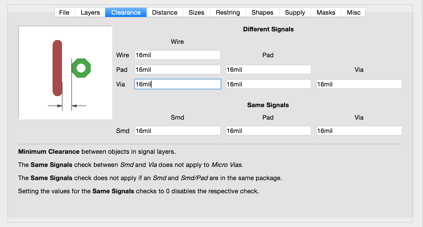
Design rules:
Before roting my board's componnets, I have to set the Design Rules which will define all the parameters that my board layout will to follow when roting,, I was using 16 mil bit to mill the routes, so I have changed the Clearance to have the minimum of 16 mil for all its routs, so that when I Auto-route the program will use these values and result it a board that I can mill directly in our Lab Milling Machine..
After that I have tested the Auto-Routing tool, but it did not work for me, and there were many overlaps*, so I decided to make the routes manually using Route tool,, I have used the main board as main guide to laying out my components,, and after couple of tries I have completed my FIRST board ever! it was little bit BIG (about 8*5cm) and there was too much wasted space!,,
*important: overlaps are NOT allowed in the Board mode, if you are making a one-side board..
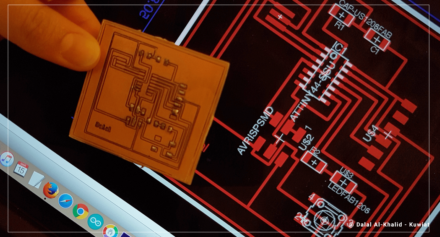 So After milling my first board, I started to feel better about making boards, so I have modified the board and tried to make best use of the space,, and I made a 3*3cm board!! it is a GREAT ACHIEVEMENT :)
[ Source File - BRD file ]
[ Source File - SCH file ]
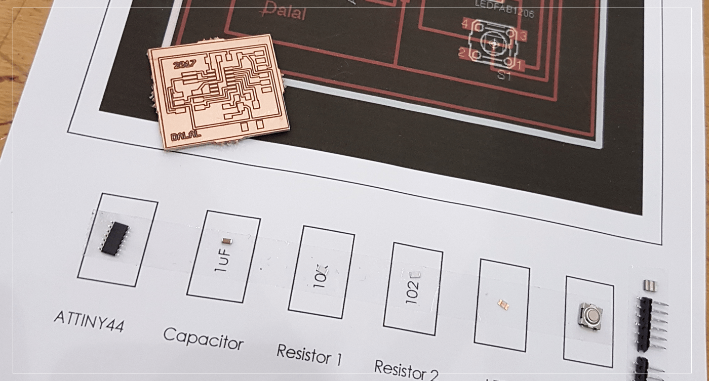
Soldering the components:
I have started by collecting the components needed for my board, and Our instructor has suggested that I stick the components in a paper using a double-sided tape,, it was a GREAT tip,, so I have printed my board and added a space for all the components, then I used the double sided tape to stick the components to ..
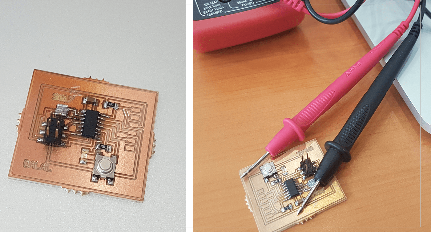
 and After completing the soldering for all the components, I have used the Multimeter to check if there is any short curict in my board,, and I have fixed what couple of areas utill I all the routes are connected perfectly without any shorts ..
Previous Week Home Next Week