Assignment 9-11. Mechanical and Machine Design
Week 9 & 11 checklist:
Our Group Project for this week is called "FindMe", it is a 2-axis machine that will be used in our electronic components drawers to ease the process of searching for specific components, as it will go directly to the specified area and switch the led ON..
TEAM DOCUMENTATION
My Work:
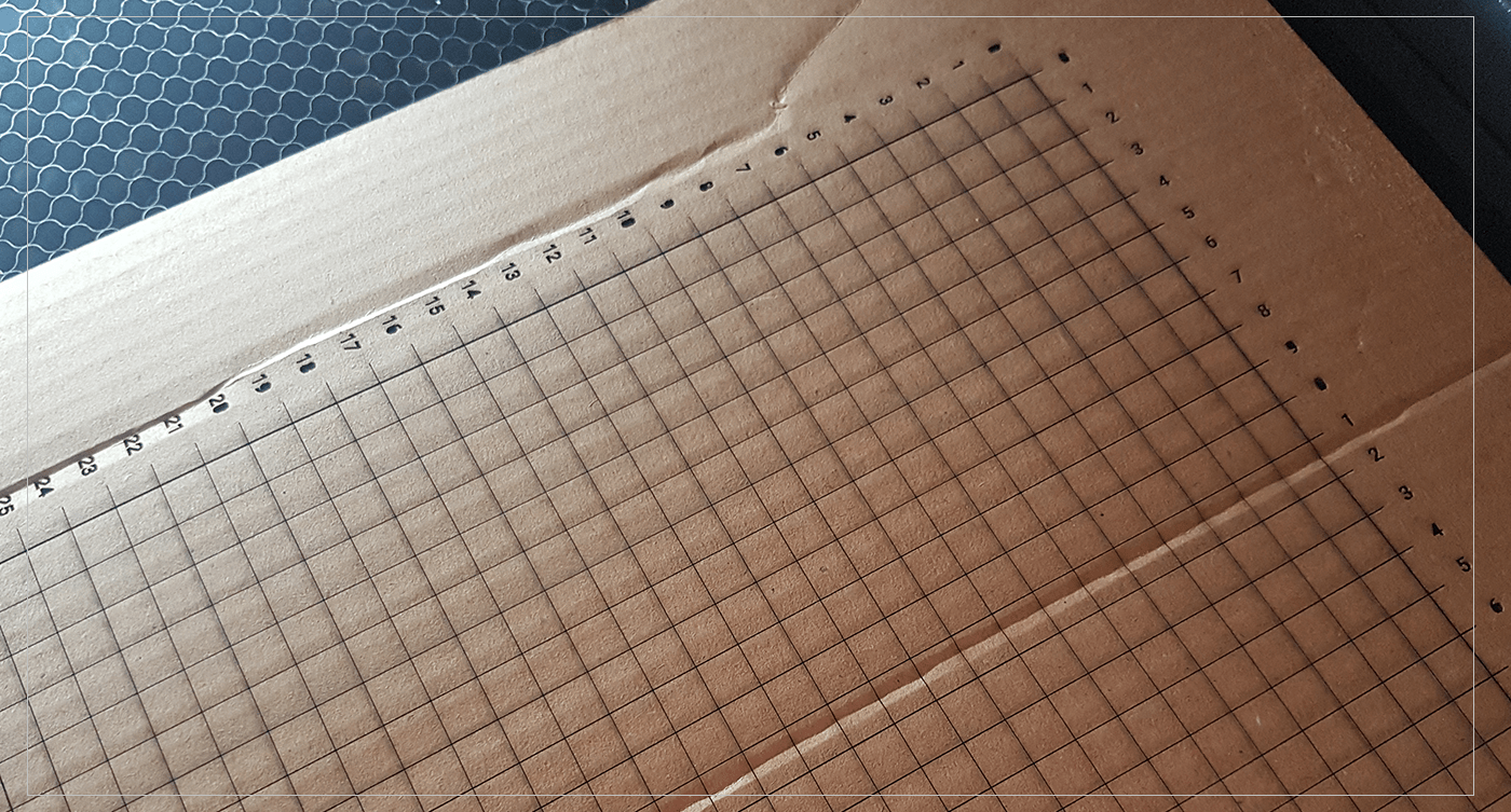
one of the main areas in designing this project, is to know where the LED will go when we enter specific X and Y axis, at first we were using regular 1 cm notepad paper to measure the distance, but it was not accurate enough,, so I have designed the grid sheet that my colleges will use to test the placement of the LED while programming..
I have started by drawing a grid in Adobe illustrator using the Line tool,, after that I have copied that line and place it 27 cm away from the first line,, by selecting both lines and I have blended them and keep a distance of 1 cm between each line,, Then I have copied and rotated these lines to make the vertical lines as well..
 After that I have write numbers on the side of each line to complete the grid sheet,, and Finally I have drawn a 40*40cm square around the line with different color to cut it, so that it would be easier to choose different setting for that in the laser cut machine ..
Laser cut:
It was an easy process to take the design and cut it using the laser cutter,, My plan was to engrave the lines and numbers, and cut the 40*40 square,, so I used these settings in the laser cut machine..
it took FOREVER to make the first couple of lines! So when I asked our instructors they told that "Engraving" is usually used to make raster images,, so it would pass the whole image line by line! while "Cut" option would go directly to the lines ,, that’s why it is faster..
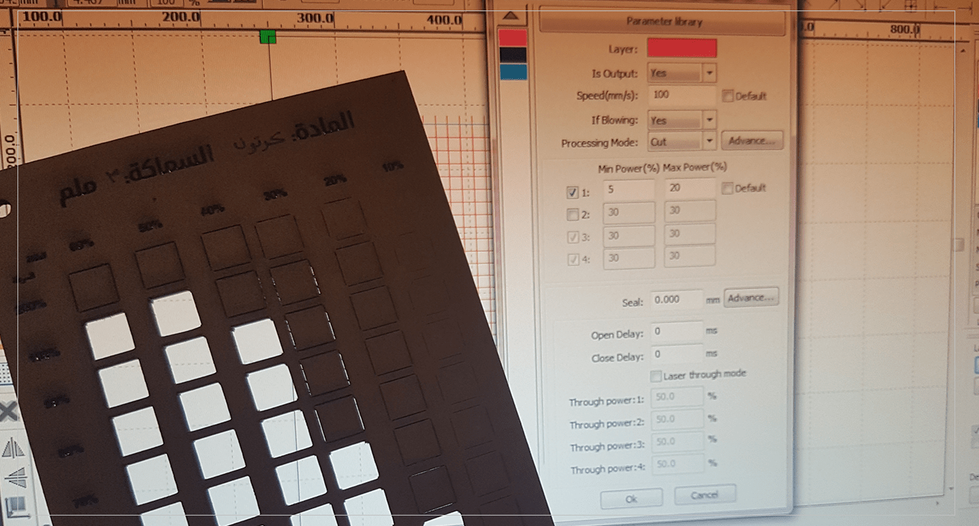 So the best option here was to use cut with low power,, so I have a " test cut sheet" to know the best settings I will use in cutting the Grid sheet,, and it was:
CUT 1: power 40 %/ speed 100 %
CUT 2: power 20 %/ speed 100 %
[ Source File - DXF File ]
[ Source File - AI File ]
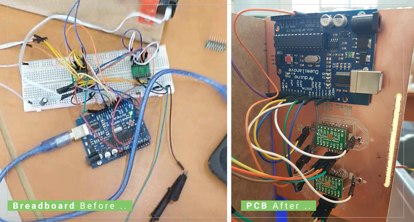
PCB Production:
I was assigned to designing a PCB that would reduce the mess of the wires used in our project..
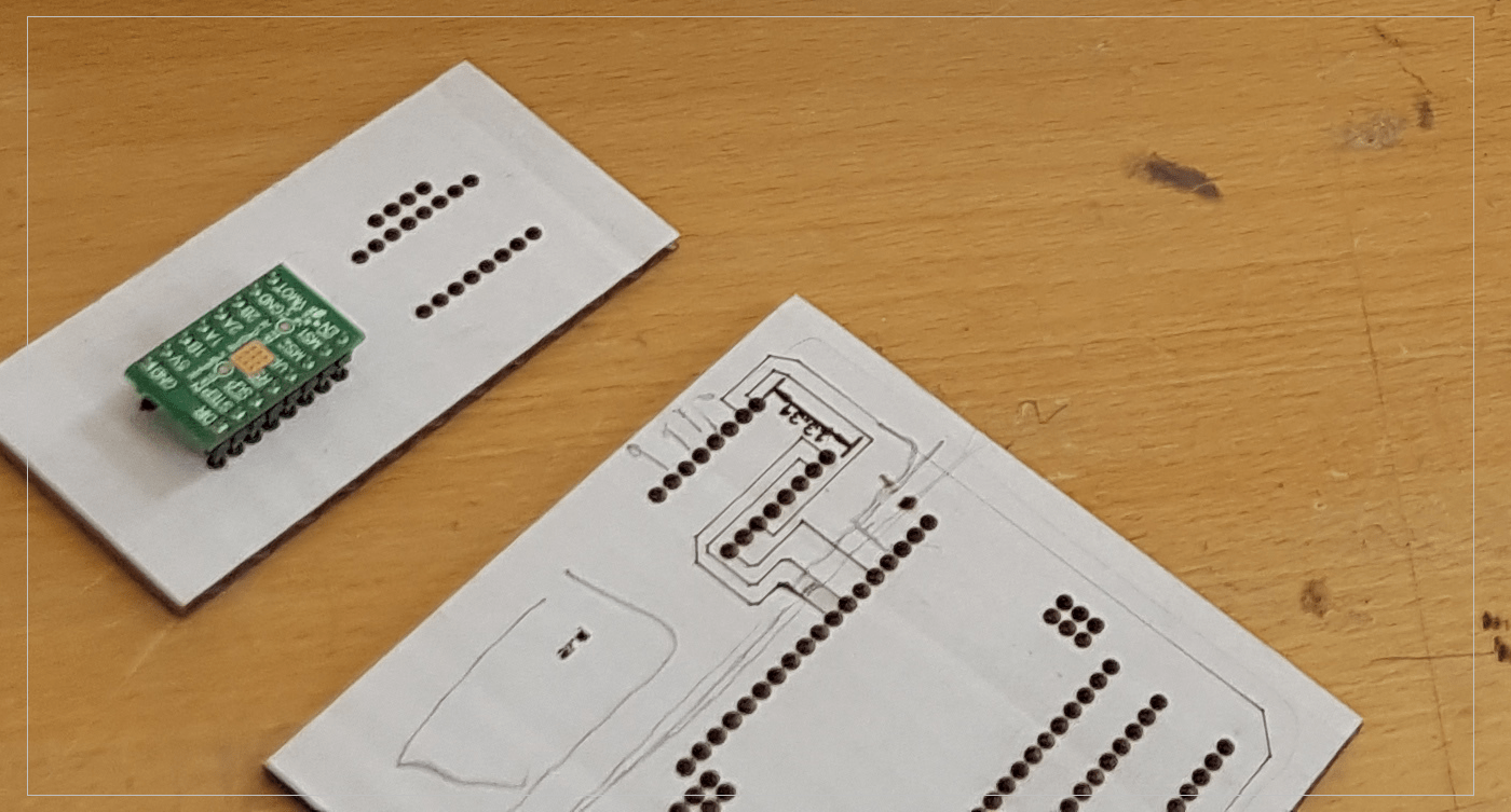
I have started by studying the pins of the stepper motor we are going to use and the connection needed for other wires ..
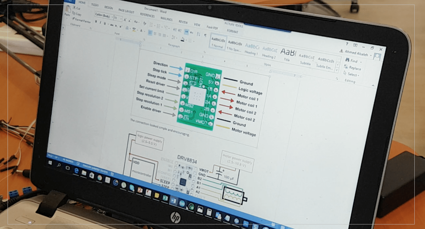 After that I have started designing the Board using Eagle Cad,, One main problem was that there were no stepper motor component in the library!! So I have used 2x 1*8pin holder to make space for the stepper motor,,
the second problem was to know the exact placement and distance between the two pin-holders,, it took couple of tests to figure the exact distance (13mm),,
Eagle Cad:
After getting the right measurements I have completed the design of the board usign eagle cad
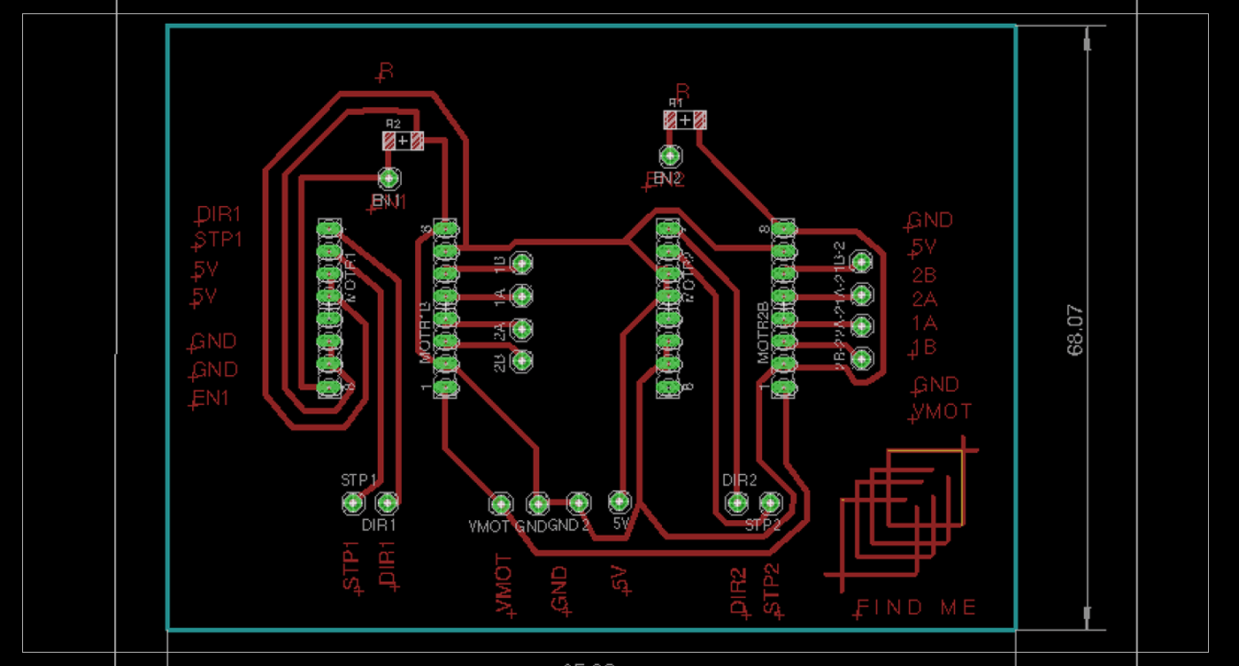 the last step was to mill and solder the components to the board which was an easy process to do .. there were couple of small problems in the board, but I have fixed them by using the xacto knife to remove any un-wanted connections.. I have added pinheads to make the connection easier with the arduino,,
[ Source File - BRD File ]
[ Source File - SCH File ]
Problems:
The Milling Machine was having some problems during the team project week,, for that reason I was not able to finish the board on time for the presentation, but I have completed the board and mill it afterword.
Future improvements:
After Completing the whole process,, We think that in the future it would be better to make our own PCB that contain all the connection on board, and we will not need to add external wires, it will make the project looks more professional. Moreover, it would be much better to have a box that contain all the electronics, as it would protect them and look neater,,
Previous Week Home Next Week