Assignment 10. Output Devices
In this week I will be designing a PCB that has an output device..
Week 10 checklist:
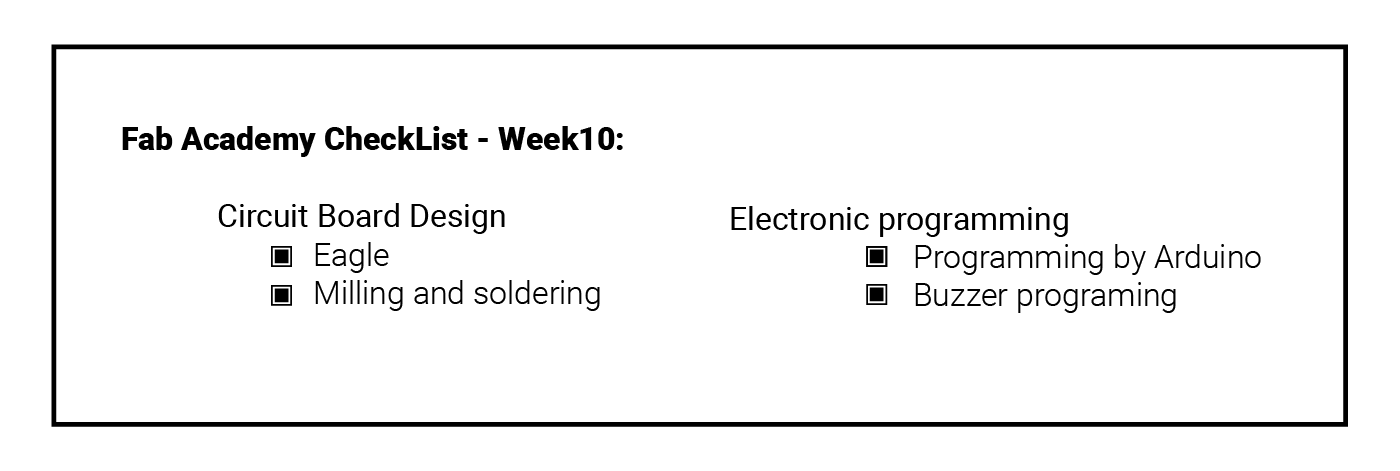
Output devices
An output device is any peripheral that receives data from a computer and converts it to physical form ( sound - image - movement - light - ... etc).
Examples of Output devices:
There are many output devices avilable on the market,, I will mention the most device I might use:
1. LED: light-emitting diodes are the simplest type of the light source, there are two types of LEDs, single color, and multi-colors(RGB LED)
2. Buzzer / Speaker: Buzzers are an electrical device, similar to a bell, that makes a buzzing noise, Speakers are devices that can produce sounds when connected to a computer or a device.
3. LCD: A liquid-crystal display which is a flat-panel display
4. Motors: An electric motor is an electrical machine that converts electrical energy into mechanical energy.,, there are three main types we use on the lab: Servo - Stepper & DC motors.
Creating my output board
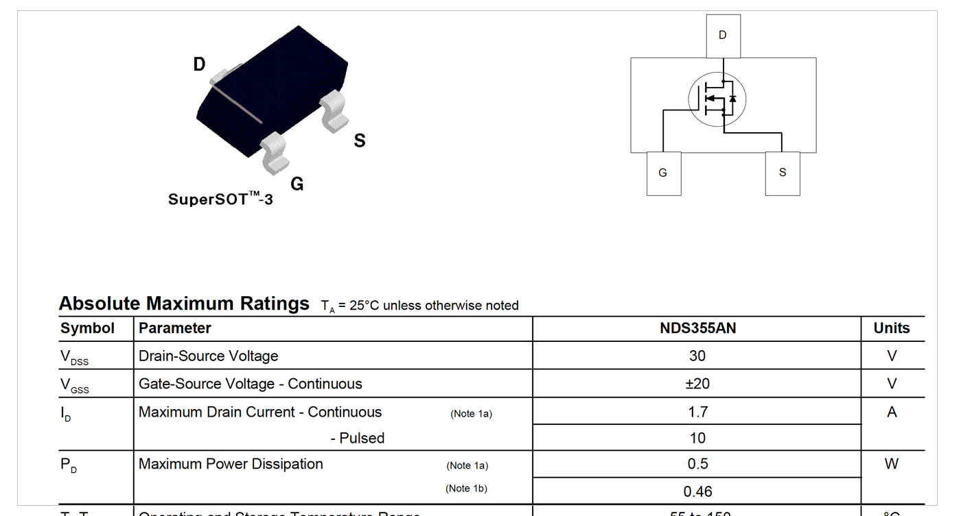
n-Channel MOSFET
I am using a new component this week to regulate the power sent to the speaker, which is n-Channel MOSFET transistor..
A N-Channel MOSFET is a type of MOSFET in which the channel of the MOSFET is composed of a majority of electrons as current carriers. When the MOSFET is activated and is on, the majority of the current flowing are electrons moving through the channel. [Source]
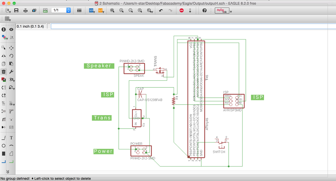
Eagle Cad:
In this week I have choosen to used the buzzer to beep up when pressing the button. First I have downloaded the Speaker board form the lecture resources, then I tried to replicate it and adding an extra switch.. after readig the Attiny45 Pinout completing the schematics, following the same procedure I have explained in Week 6 ..
 Then I have tried to make the routes Manually,, but I could not do them all :( .. So I used Auto-routing which was very good!..
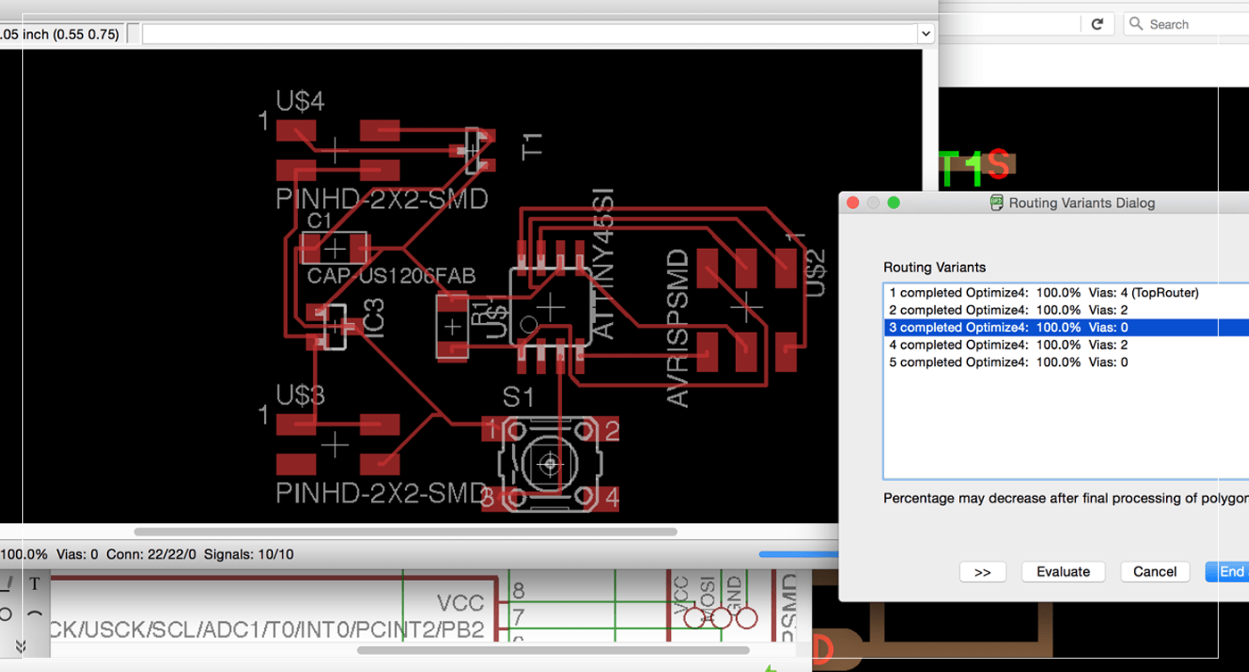
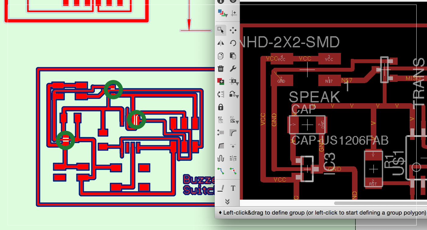
After that, I have decided to increase the width of the route in order to make it easier to mill and reduce the chance of shortcircut!,, by doing that I have faced a new problem, there was not enough space for the bit to cut in some places! and it would ether miss these spots, or have a shortcircuit on them!I have tried to fix these areas by using thin routes,
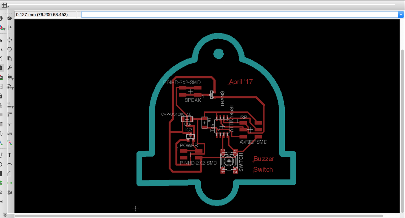
 After that I wanted to go one step further by drawing a shape for my PCB, I want it to represent the function of the PCB, which is a Bell and .. it was interesting to cut the PCBs in an irregular shape .. It was little bit challenging to draw insde Eagle cad, as the tools were not designed for this purpose!, I have also tried to import DXF or Bitmap images but it did not work! so I took my time to draw my bell in Eagle using lines and curve tools,, Joel Gegner have published an interesting video explaining that process ..
Milling The board:
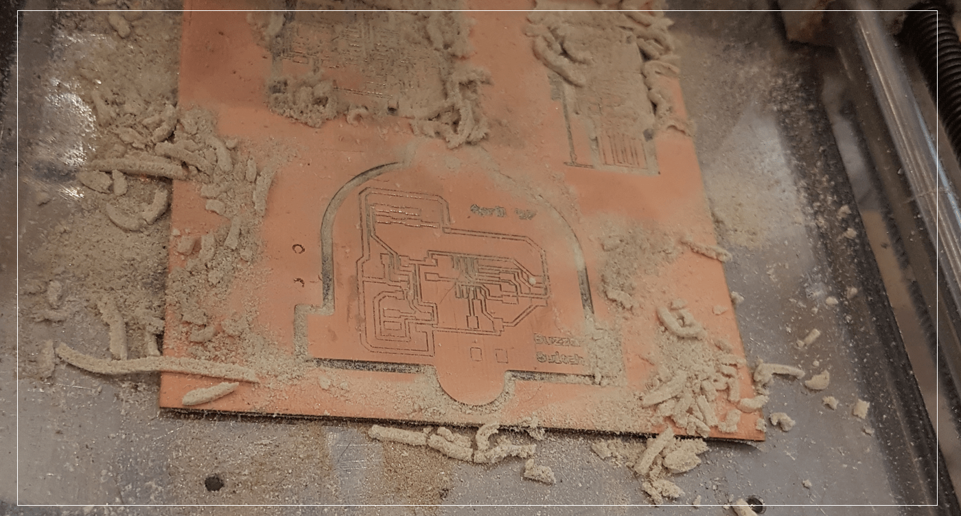
I have learned some new skills while milling my bell board, two of the most important lessons were:
1. Using the milling layer in Eagle Cad allows me to cut the board on a custom shape.
2. I have accidentally move the milling shape while I was on the last step ( pcb was already engraved, and I was going to cut the outer edge)! so I have learned how to reposition the design by making a test cut for portion of the design and stopping the machine when it was on the wrong position until I figure the perfect position!
Soldering:
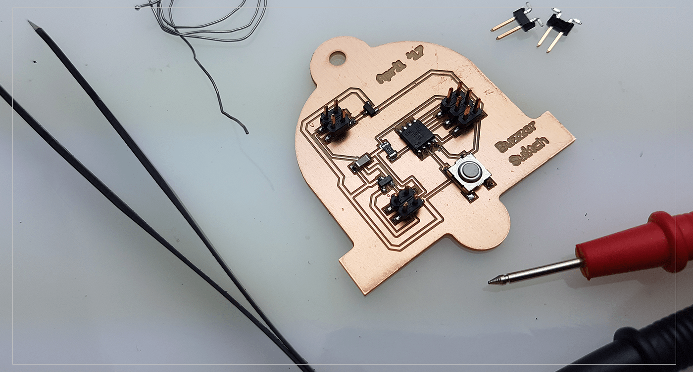
By using the regular method of soldering ( melting the led directly into the pads, then attach the components one by one) I have completed adding all the components to my bell board.. Next is to program ..
Programming and testing:
After checking the board for any short-connections, and fixing them,, I have programmed the board using Arduino IDE and writing the follwoing code, which will make the buzzer work when pressing the button ,, by just modifying the code I have used in week 6, I was able to achive the desire goal ( in the future I would like to experiment with different melodies like Supermario song).. but for now,, my mission is to make a working Buzzer board, and I did : )
The Code
const int btn = 4;     // pushbutton pin
const int buz = 1;      //Buzzer pin


void setup() {

  pinMode(buz, OUTPUT);    // Buzzer pin as an output:

  pinMode(btn, INPUT);    // pushbutton pin as an input:
}

void loop() {

  buttonState = digitalRead(btn);    // read the state of the pushbutton value:


  if (buttonState == HIGH) {				 // check if the pushbutton is pressed.

    digitalWrite(buz, HIGH);				 // turn Buzzer on:
  } else {

    digitalWrite(buz, LOW);				 // turn Buzzer off:
  }
}
[ Source File - BRD file ]
[ Source File - SCH file ]
Previous Week Home Next Week