Assignment 15. Networking
In this week I will be making a Network and link two boards using the I2c Serial comunication..
Week 15 checklist:
Networking Methods:
In a digital communications system, there are 2 methods for data transfer: Parallel and Serial. Parallel connections have multiple wires running parallel to each other (hence the name), and can transmit data on all the wires simultaneously. Serial, on the other hand, uses a single wire to transfer the data bits one at a time. [Source]
I2C Protocol
The Inter-integrated Circuit (I2C) Protocol is a protocol intended to allow multiple “slave” digital integrated circuits (“chips”) to communicate with one or more “master” chips. Like the Serial Peripheral Interface (SPI), it is only intended for short distance communications within a single device, it only requires two signal wires to exchange information.[Source] and this the option I will go for ..
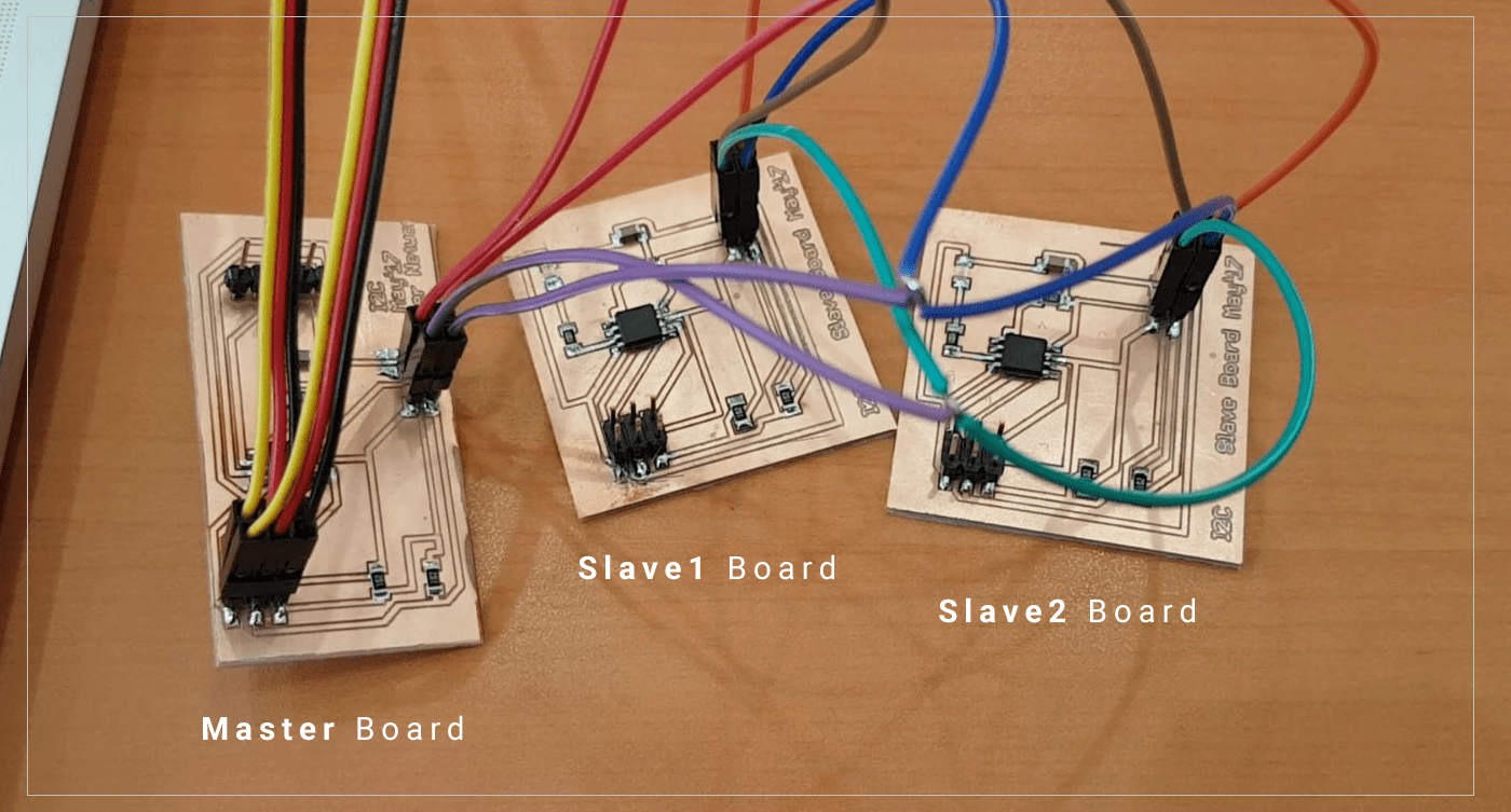
My Network Boards:
I am planning to connect two slave boards using I2C comunication method, to send signals from the one master to both boards, and using the least amout of wires.
Designing and Milling the Board:
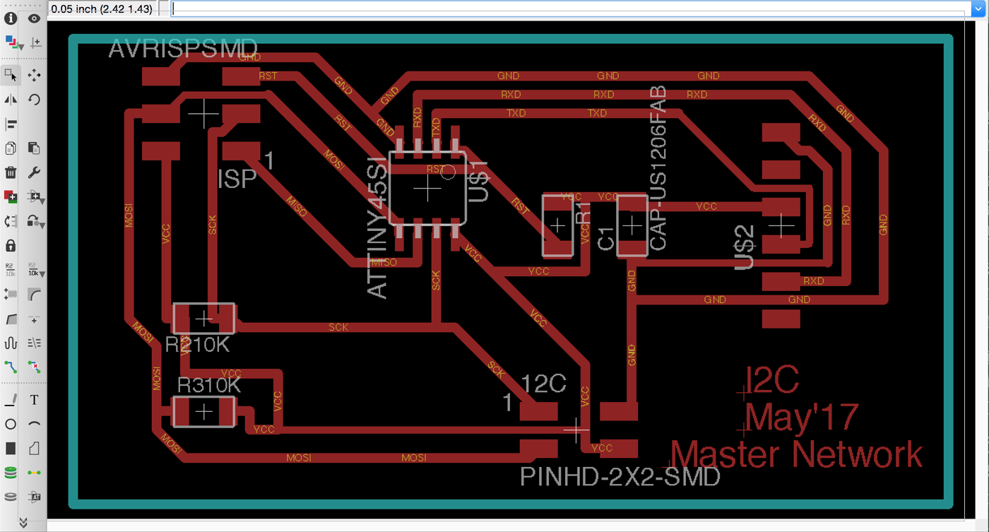
I have designed both the Master and the Slave boards following the designs provided by the academy.. I have used Eagle to design them,,
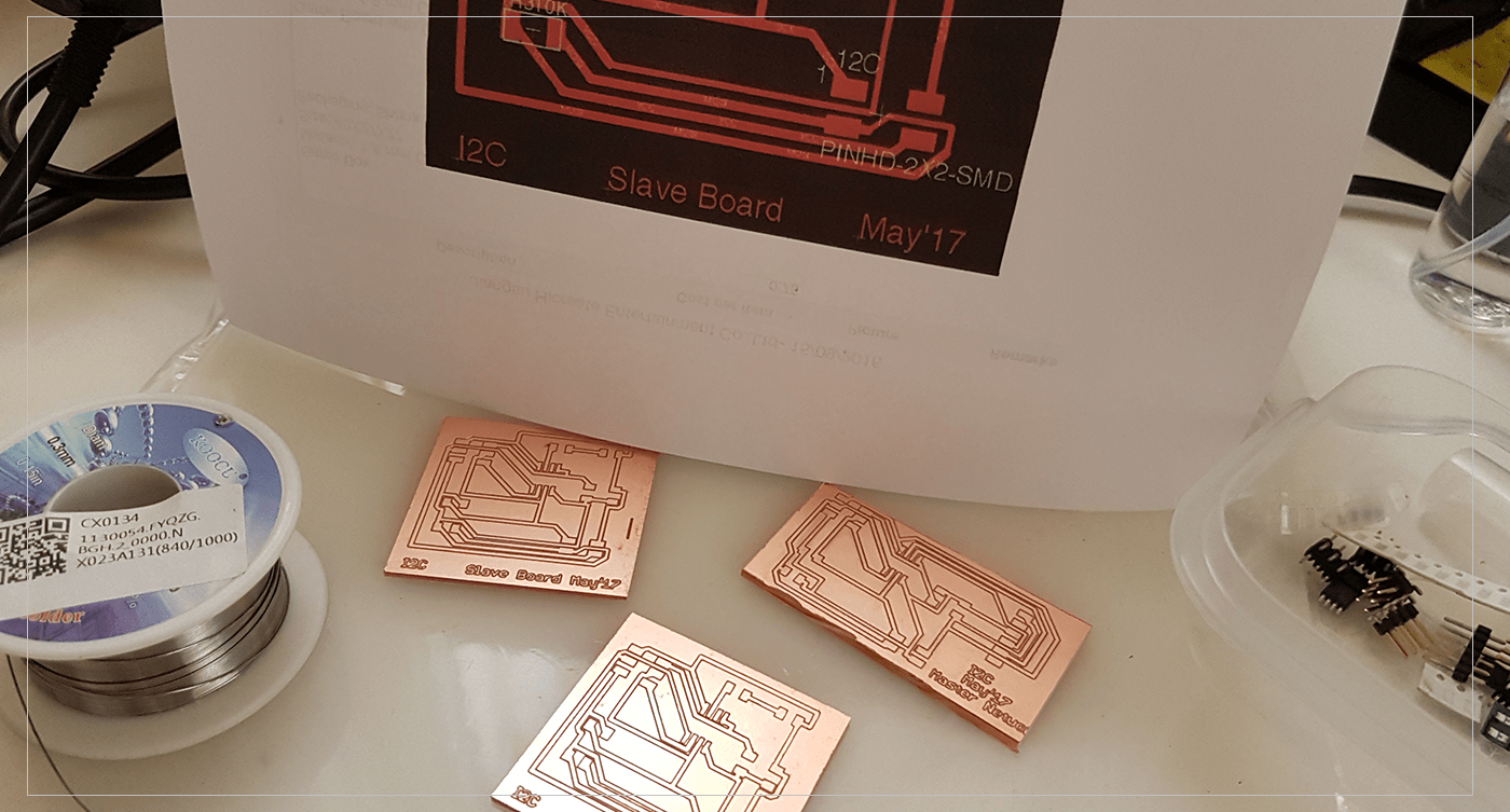
 After that I have milled all the boards (1 Master, and 2 Slaves) using our PCB Milling machine,, it took less than 15 mins to complete all the boards..
Soldering The Boards:
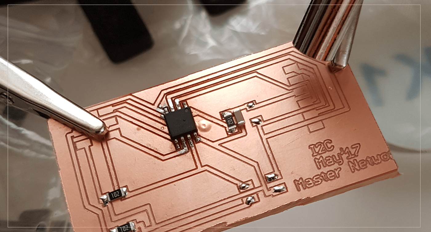
I have used a simple way to solderf the components to the board by using the hot air gun, it was very easy and my soldering on these boards is the best so far ..
THE PROCRESS : Solder little led on all the spaces where the components will be placed using the soldering gun, then I would place all the components on their spaces. After that I will reduce the Air-Flow of the hot air gun to the minimum, and experiment with the temperature (usually between 300-450), by moving the gun on circular motion, over the components, and using a tweezer to hold/correct the position of the components..
CAUTISON! holding the soldering iron still over the component/board for a long time will burn/ruin them!
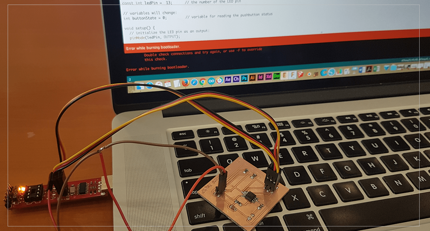
Programming the Boards:
The first step was to check the if the connections were fine, which was done by burning the bootloaders in all the boards, first I have found couple of problems in both slave boards, and after analyzing the problem, I have detected several areas that might be the source of the problems I was facing,, and I have successfully solved all the problems..
 After That I have created my own Serial connection wires to connect my boards directly without using the BreadBoard, by cutting 2 F2F connectors and solder them together ..
The Last step was to program the boards and check.. I have used the following code and make sure that the LED pins match the ones I have used in my board design.. The pin should be matching the name of the Attyin45 pinout names (eg.PB3 not only 3 as we used to write in Arduino).. The code work perfectly : )
How does the code works?
In the Master code I have assigned the address for each slave as follows:
TinyWireM.beginTransmission(0x1);
TinyWireM.beginTransmission(0x2);
So the Master board will be sending a signal for Slave one first, then it will wait for 1 sec, then it will send a signal for the second board..
delay (1000);
In the Slaves Code the LED will Blink when the board receives a signal from the Master.. then after 1 sec. the other board will Blink when it receives a signal from the Master,,
Master Code
#include

void setup()
{
  TinyWireM.begin(); // join i2c bus (address optional for master)
}

byte x = 0;
byte x1 = 0;
void loop() {
  TinyWireM.beginTransmission(0x1); // Slave 1
  TinyWireM.write(++x % 2);
  TinyWireM.endTransmission();

  delay(1000);
  TinyWireM.beginTransmission(0x2);  // Slave 2
  TinyWireM.write(++x1 % 2);
  TinyWireM.endTransmission();

  delay(1000);
}
Slave1 code
#define output(directions, pin) (directions |= (1 << pin)) // set port direction for output
#define input(directions, pin) (directions &= (~(1 << pin))) // set port direction for input
#define set(port, pin) (port |= (1 << pin)) // set port pin
#define clear(port, pin) (port &= (~(1 << pin))) // clear port pin

#define LED_PIN PB3

#define I2C_SLAVE_ADDRESS 0x1 // Address of the slave 1

#include

void setup()
{
    output(DDRB, LED_PIN);
    clear(PORTB, LED_PIN);

    TinyWireS.begin(I2C_SLAVE_ADDRESS); // join i2c network
}

void loop()
{
  byte recd = 1;
  if(TinyWireS.available()) {
      recd = TinyWireS.receive();
      if(recd == 1) {
          clear(PORTB, LED_PIN);
      } else {
          set(PORTB, LED_PIN);
      }
  }
}
Slave2 code
#define output(directions, pin) (directions |= (1 << pin)) // set port direction for output
#define input(directions, pin) (directions &= (~(1 << pin))) // set port direction for input
#define set(port, pin) (port |= (1 << pin)) // set port pin
#define clear(port, pin) (port &= (~(1 << pin))) // clear port pin

#define LED_PIN PB3

#define I2C_SLAVE_ADDRESS 0x2 // Address of the slave 2

#include

void setup()
{
    output(DDRB, LED_PIN);
    clear(PORTB, LED_PIN);

    TinyWireS.begin(I2C_SLAVE_ADDRESS); // join i2c network
}

void loop()
{
  byte recd = 1;
  if(TinyWireS.available()) {
      recd = TinyWireS.receive();
      if(recd == 1) {
          clear(PORTB, LED_PIN);
      } else {
          set(PORTB, LED_PIN);
      }
  }
}
[ Source File - Master BRD ]
[ Source File - Master SCH ]
[ Source File - Slave BRD ]
[ Source File - Slave SCH ]
[ Source File - Master- Arduino Library ]
[ Source File - Slave- Arduino Library ]
Previous Week Home Next Week