Assignment: read a micro-controller data sheet and program it in different Embedded programming techniques to do something you want.
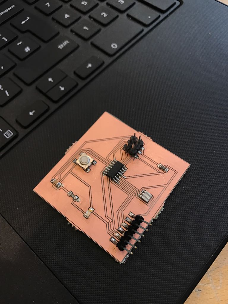
For the programming purpose I will use the board I already made in my week six assignment, and I check it if it is working or not and it is good to go
Micro-controller is a control device which incorporates a microprocessor. For studying purpose I referred to the ATtiny44 micro-controller data sheet. the data sheet explain many things like micro-controller pin configuration and description and overview along with general information and AVR architecture and information about the memories.
There many short (initial letters) forms need to be defined and understood such as :
1) PDIP : Plastic Dual In-Line Package (Through hole mount)
2) MLF : Micro Lead Frame
3) QFN : Quad Flat No-leads
4) VQFN : very thin quad flat no-lead
5) SOIC : Small Outline Integrated Circuit (surface mount)
pin configuration of ATtiny44
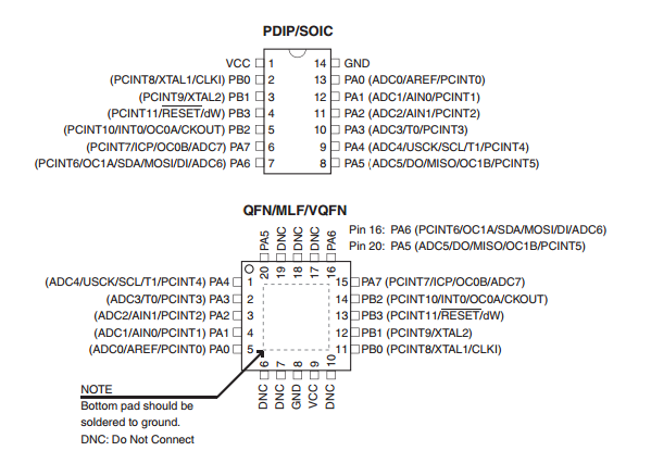
It is important to know that:
VCC pin is the power supply voltage.
GND pin is the ground.
PORTB(PB3:PB0) – Port b is a 4-bit bi-directional input and out put port. in that PB3 has RESET capacity also it is used as an input or output pin.
PORTA(PA7:PA0) - Port a is 8-bit bi-directional input or output buffers that have symmetrical direction.

programming or burning a microcontroller means to transfer the program data from a compiler to micro-controller the program of a micro-controller is generally written using C or assembling language then the compiler generate a hex file which contains the machine language instruction understandable by the microcontroller.
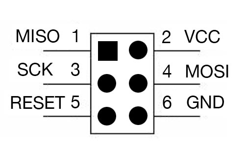
MOSI(Master Out-Slave IN):Communication line from In-system Programmer to target AVR being programmed.
MISO (Master in-Slave Out):Communication line target AVR to in system programmer.
SCK (serial clock):programming clock,generated by the In-system programmer (Master).
GND (common ground):it connect to the ground
RESET: to enable in-system programming
VCC: to allow simple programming of targets operating at any voltage,the in-system programmer can draw power from the target .
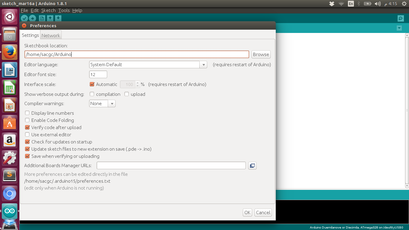
For the programming we must use a software so I choose Arduino IDE and downloaded it to program ATtiny.
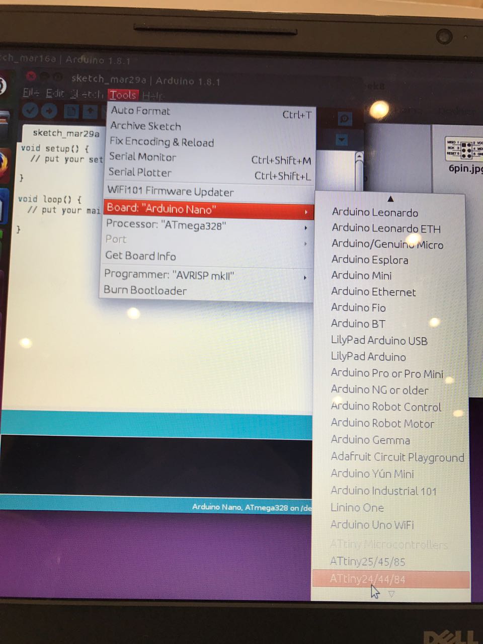
Then we have to add our board in the list following these steps:
File, preferances, add ATtiny git library link to the field “Additional board manager URL’s:”
Since ATtiny44 is our microcontroller choose:
tools→ board→ ATtiny
tools→ processor→ ATtiny44
tools→ programmer→ USBtinyISB
.
.
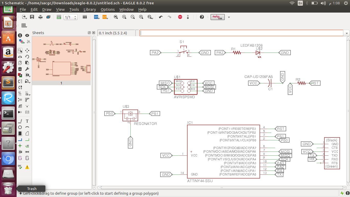
The LED Light is connected to PA3 ATtiny44 pin in my board, such information is essential to program the board.
const int buttonPin = 2;
const int ledPin = 3;
int buttonState = 0;
void setup() {
pinMode(ledPin, OUTPUT);
pinMode(buttonPin, INPUT);
}
void loop() {
buttonState = digitalRead(buttonPin);
if (buttonState == HIGH) {
digitalWrite(ledPin, HIGH);
delay(1000);
digitalWrite(ledPin,LOW)
}
else {
digitalWrite(ledPin, LOW);
}
void setup() {
pinMode(3, OUTPUT);
}
void loop() {
digitalWrite(3, HIGH);
delay(1000);
digitalWrite(3, LOW);
delay(1000);
}