This week assignment is to create a echo hello-world board with at least two additional components, a LED and a switch hello.ftdi.44.cad file is the source library. there are 4 free pins in the microcontroller.
So I will develop an echo.helloisp initially with a additional switch, resistance and a LED then I might put it to some use.
Eagle :
EAGLE is a scriptable electronic design automation application with schematic capture, printed circuit board layout, auto-router and computer-aided manufacturing features. EAGLE stands for Easily Applicable Graphical Layout Editor (German: Einfach Anzuwendender Grafischer Layout-Editor) and is developed by CadSoft Computer GmbH. Cadsoft Computer GmbH was acquired by Autodesk Inc. in 2016. (from
www.wikipedia.org
)
I Choose it over other applications like 123D design , KiCAD and Altium designer because I liked the interface and I believe it is more user friendly.
I used the hello board file from http://academy.cba.mit.edu/classes/embedded_programming/index.html#echo and added a resistance, switch and a LED after watching some tutorials about drawing schematic and the board which was very helpful to get started.
There are components needed for the design available in fab library that we should add them following the below steps
1. Download Fab Library fab.lbr from
http://archive.fabacademy.org/archives/2017/doc/electronics/fab.lbr
2. Put it in the installation folder
3. Open eagle Library -> Use and choose the .lbr file Library -> Update all
Then goto file -> New -> Project and right click on the project and select schematic.
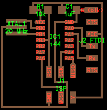
The components needed are Attiny 44, 20Mhz crystal, 10k resistor, 499 ohm resistor , 1uf Capacitor , LED(2 Nos), press switch and 2x3 Header
Now I add the components on the blanc screen by typing “add” inside the text box on the top and add all the components and started connecting them using “labeling” method by name labeling the cables by typing name in the address bar and some minor direct “Net” connection by dragging the line between components connection for easy parts so everything is clear visible and nice looking.
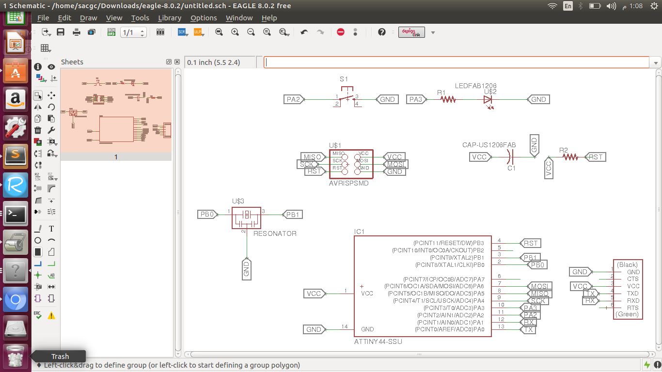
Then I generate the(switch to board) file to route the components without overlapping. i can route either Manually or Automatically and since I have too many lines I choose automatic after I fixed the width of routing line to be 16 mil to avoid shorts circuits while milling. After so many layouts of the components in many different ways and typing ripup; to disconnect the routs and try again and again and again I got 100% connections and I ended the job.
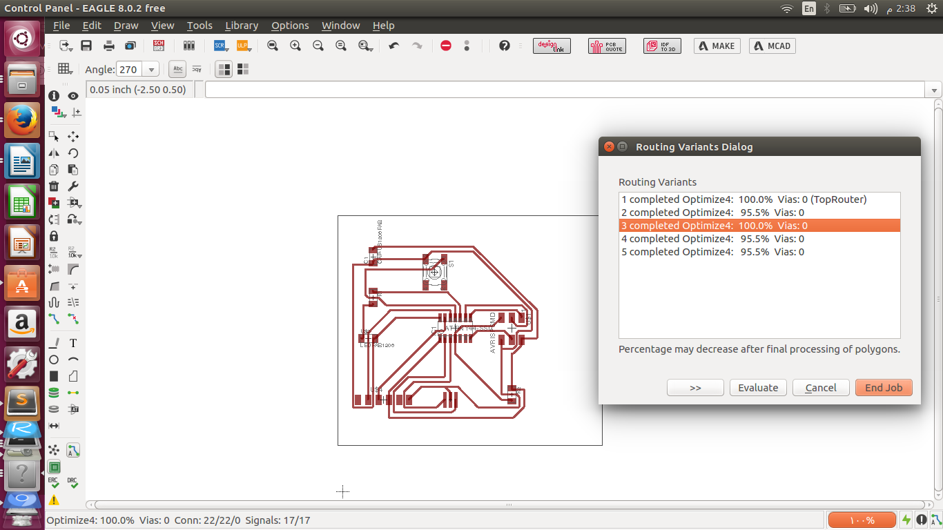
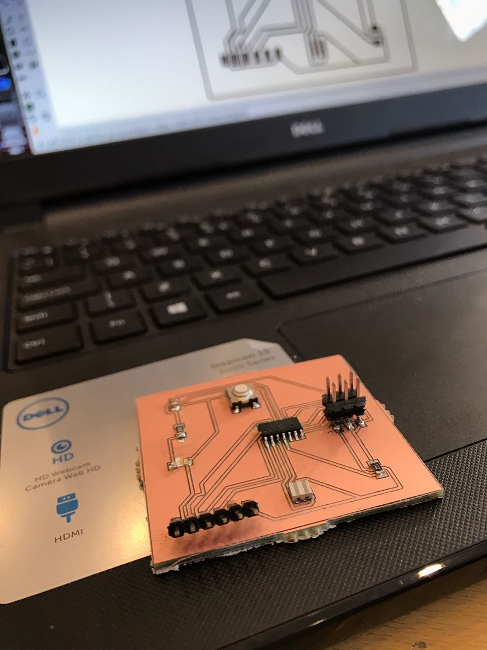
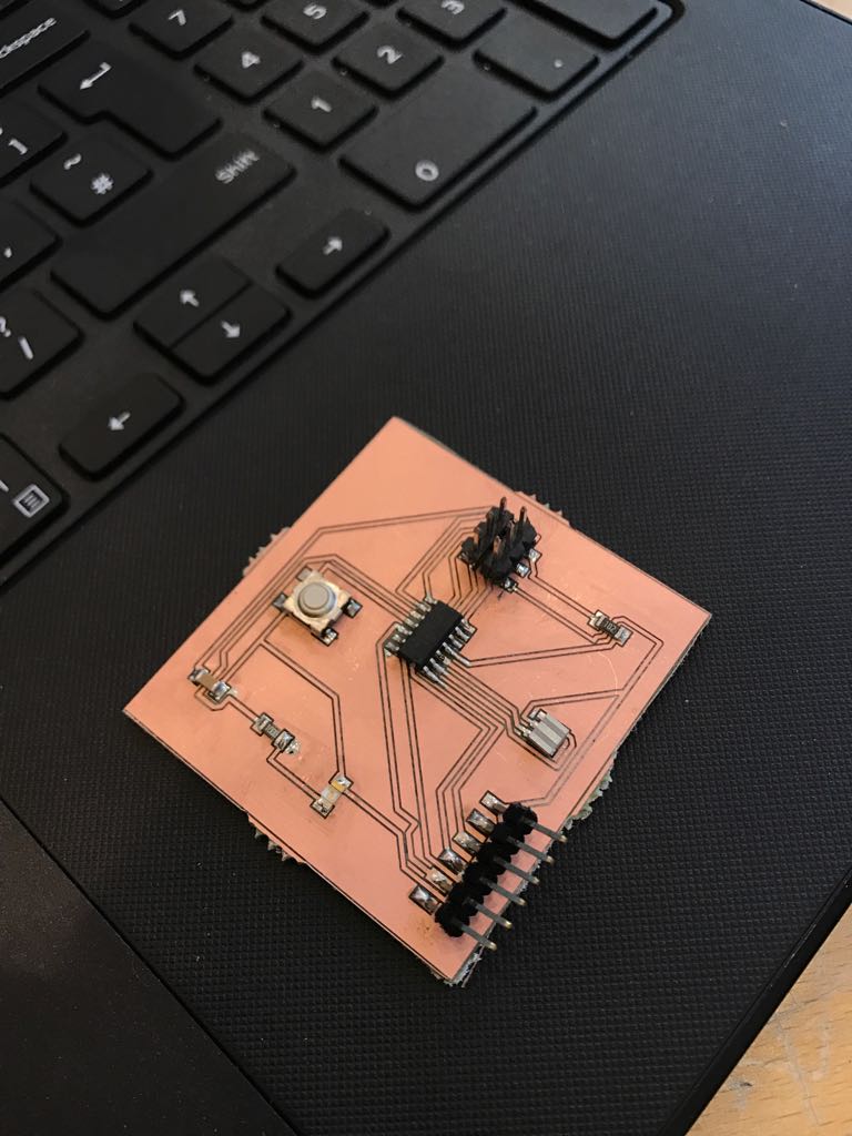
I saved the file in .brd format and converted it to gerber file .cmp extension to open it in CirqWizard and mill the circuit board on the copper sheet.
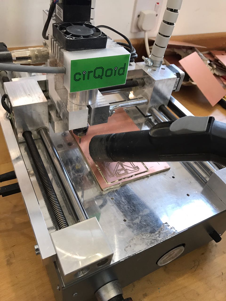
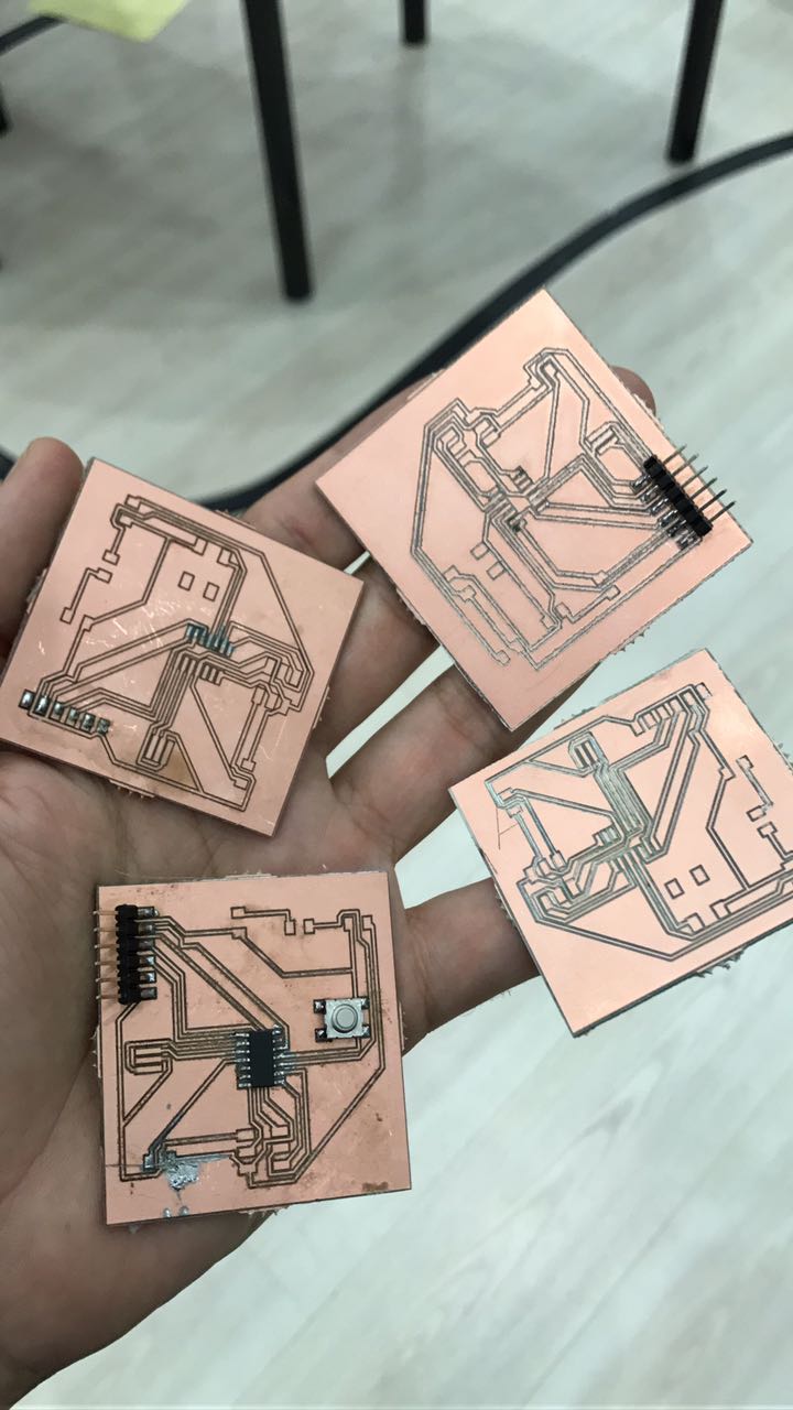
During milling and soldering I faced too many short circuits and had to repeat the board 5 times because of the conical milling head which makes shorts if you mill shallow and eat whole lines if you mill deeper.
I chose the LED resistor 100 ohm because the resistor
Using the ohms law I calculated the required resistor value as follows
R = (Vs - Vf) / Ifc
=> R = (5V - 2.8V) / 0.02A (20 mA)
=> R = 110 ohm
but we don’t have 110 so I used 100 ohm resistance which is the closest value and finished the soldering making sure everything is connected perfectly and there are no shorts in my board.
These are the componants :
*Attiny 44
*10k resistor
*100 ohm resistor
*LED
*press switch
*2x3 Header
*1uf Capacitor
*20Mhz crystal