Micro controller is a small computer (system on a chip) , it contains one or more CPU’s and memory and programmable input and output peripherals. It is designed for embedded applications, in contrast to the microprocessors used in PC’s or other general purpose applications consisting of various discrete chips.
Automatically controlled products and devices use micro controllers, such as automobile engine control systems, implantable medical devices, remote controls, office machines, appliances, power tools, toys and other embedded systems.
Some micro controllers may use four-bit words and operate at frequencies as low as 4 kHz, for low power consumption (single-digit milliwatts or micro watts). They will generally have the ability to retain functionality while waiting for an event such as a button press or other interrupt; power consumption while sleeping.
I have wondered whats inside the Attiny and how its made and how it understands the power and data and organize all of that.
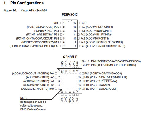
Pin Codes :
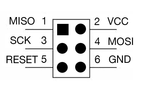
In here six pin ISP cable is used to connected the micro-controller and programmer.
SCK (Serial Clock) : programming clock, generated by the In-system programmer (Master).
MOSI (Master Out-Slave IN) : Communication line from In-system Programmer to target AVR being programmed.
MISO (Master in-Slave Out) : Communication line target AVR to in system programmer.
GND (Common Ground) : It connects to the ground.
RESET : To enable in-system programming.
VCC : To allow simple programming of targets operating at any voltage, the in-system programmer can draw power from the target.
Programming :
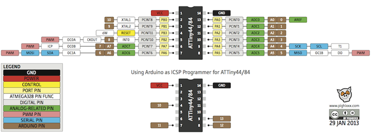
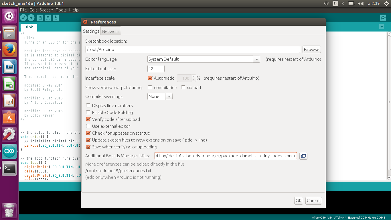
I used Arduino to program my board. At the beginning I added the Attiny 44/84 library to the Arduino by using this URL
as shown below :
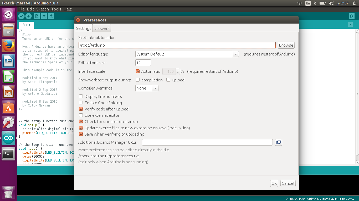
I opened Arduino , then File>Prefrences.
Then I pasted the url for the attiny library in the Additional Boards Manager URL’s text bar.
Problems :
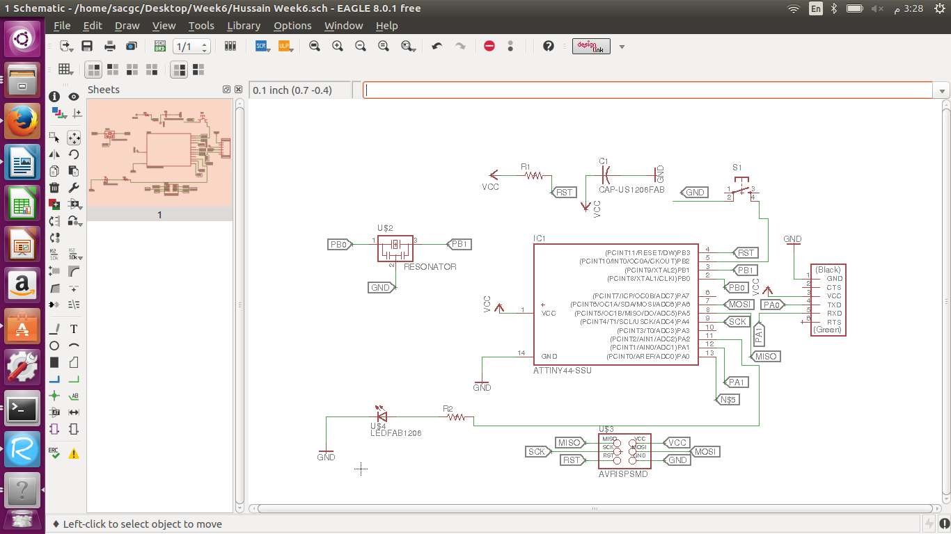
Mistake : Board designed in week 6 had a mistake
The board I designed in week 6 had a problem which was that I forgot to label Attiny pin # 13 as shown above.
What I did :
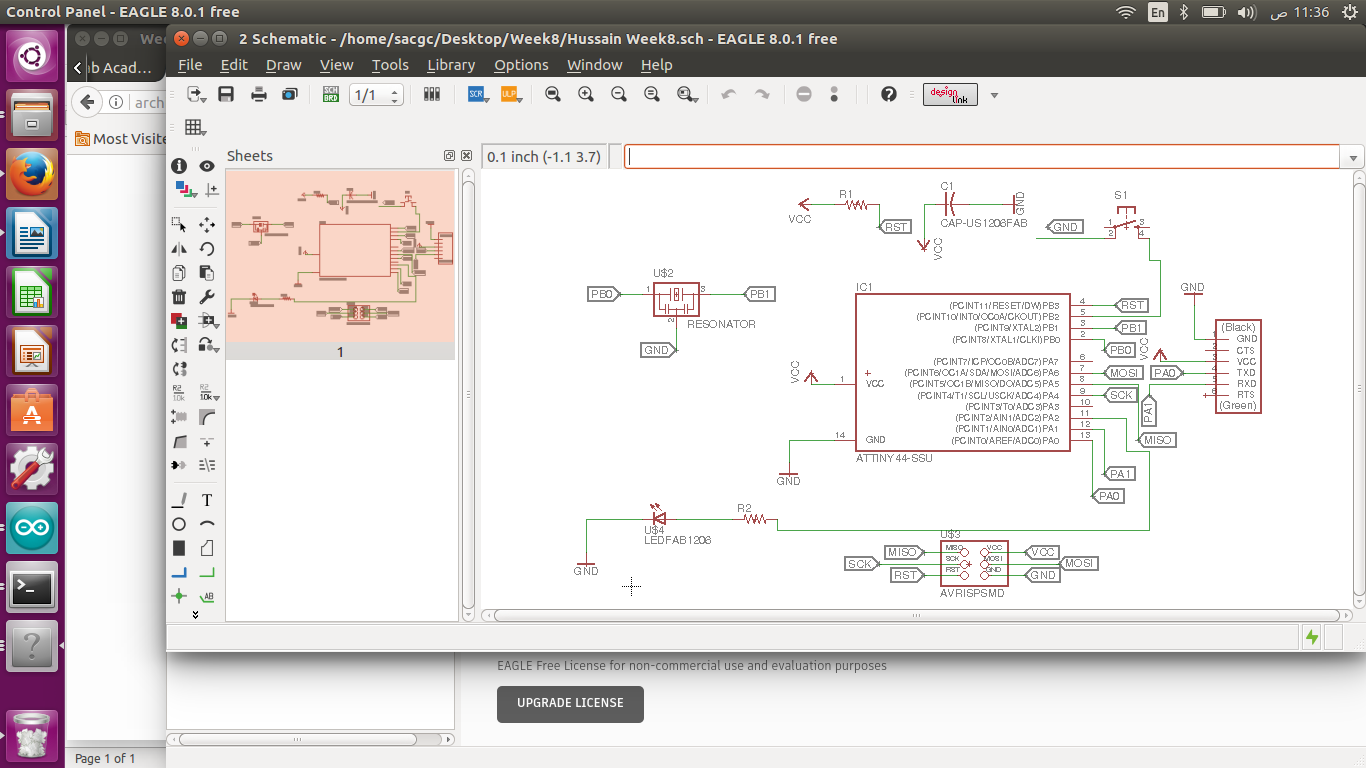
I fixed the labeling issue by labeling pin # 13 and redesigned my board.
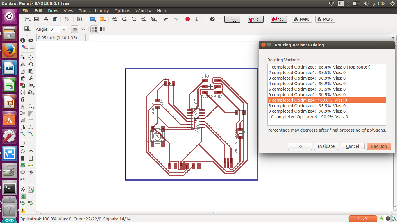
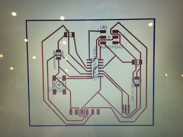
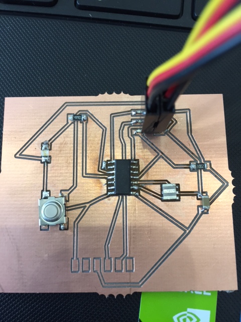
I rerouted again and the above was my final board.
Then I manually fixed the route of some parts of the design to minimize the risk of errors happening while soldering.
After soldering I had a couple of shorts which resulted in errors when burning the boot loader in Arduino. -F command that forces the compiler to neglect errors.
What I did again :
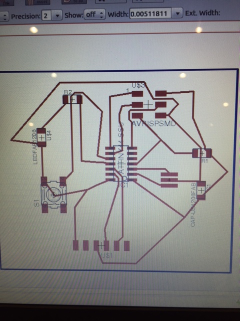
I changed the labeling in my schematic design , especially the switch. To try again to reduce the chances of errors.
Then I auto rooted the components and after auto-rooting , I manually fixed some of the roots to reduce the risk of having shorts while soldering which is the most difficult thing for me.
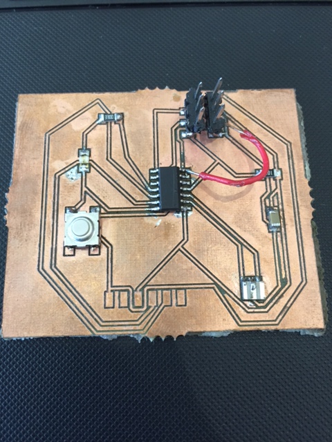
Above is my final board after soldering.
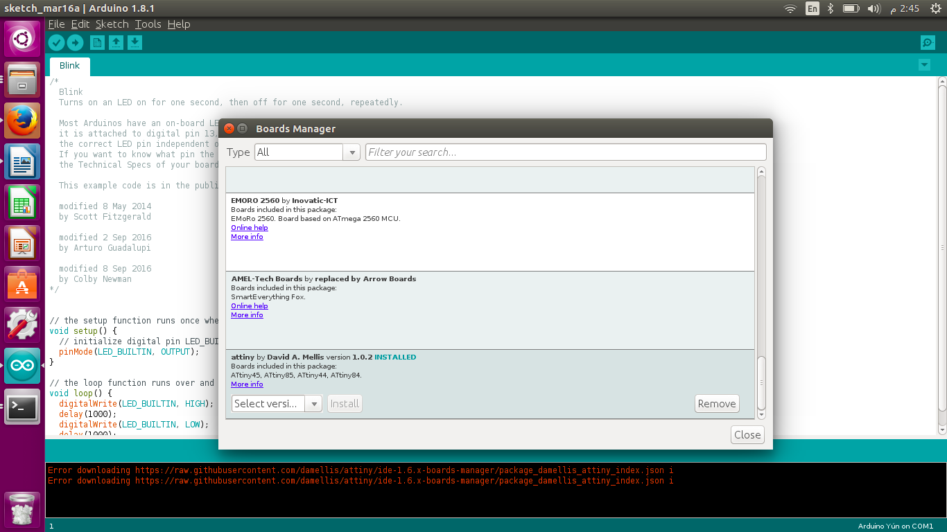
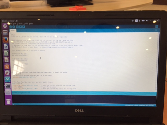
Finally I burned the boot loader successfully , as it shows in the blue ribbon down.
Programming :
I used the below code to program my board.
const int buttonPin = 3; // the number of the pushbutton pin
const int ledPin = 2; // the number of the LED pin
// variables will change:
int buttonState = 0; // variable for reading the pushbutton status