Mechanical Design & Machine Design
Week 9 & Week 11
Assignment :
-
Make a machine, including the end effector, build the passive parts and operate it manually.
-
Automate your machine. Document the group project and your individual contribution.
Group Project :
Our group project was named “Find Me” , which finds the drawer/shelf and switches the LED light on to determine the drawer needed.
My Contribution :
First of all I contributed by suggesting the idea along with my colleagues , my suggestion was to make a teddy bear crane machine game using x-axis and y-axis , and a rolling tool to go down catch the toy. But then we decided as a group to make a machine that determines the item object is in witch drawer by a LED light going to the object that s defined in which drawer.
Bearings
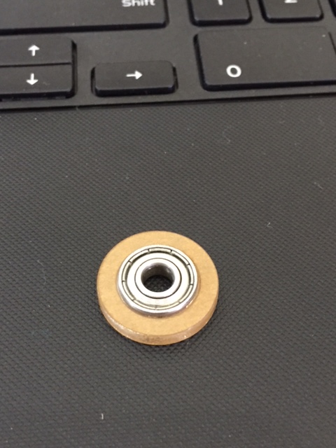
Second I tested the fittings of the ring shaped component as shown below :
The fitting I tested before they designed this object by the below deigns.
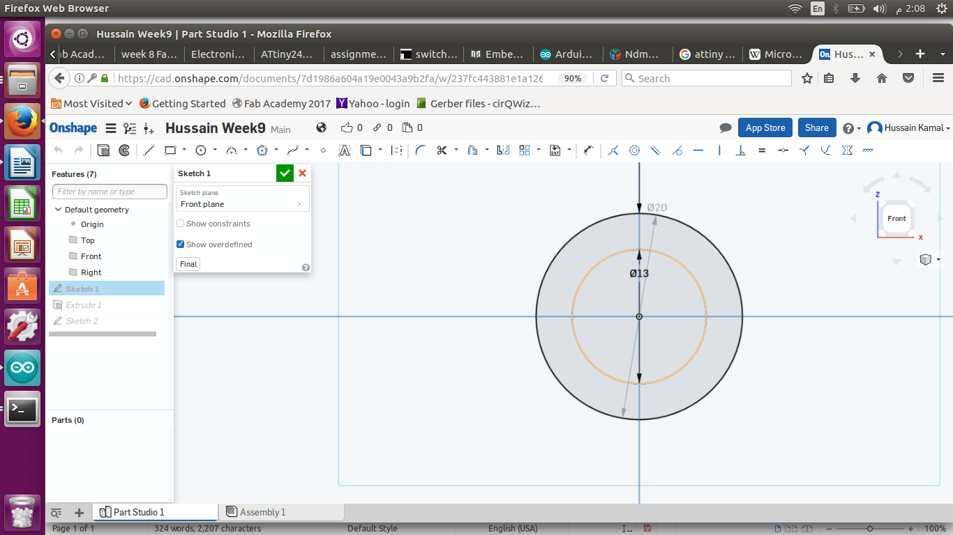
I designed a bearing for one of the holders of the stepper motors we used in our group project.
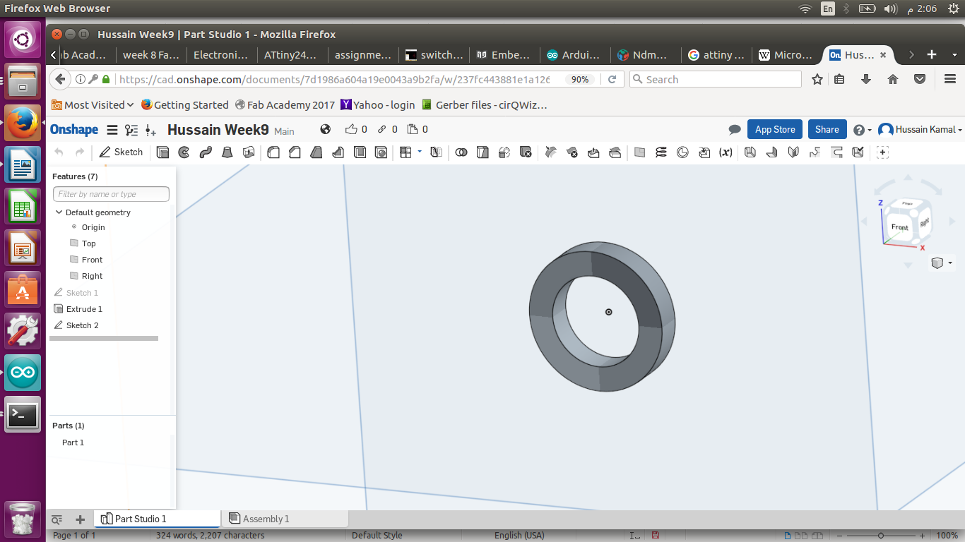
I extruded my design by 3mm to see how it will be after I cut the acryllic.
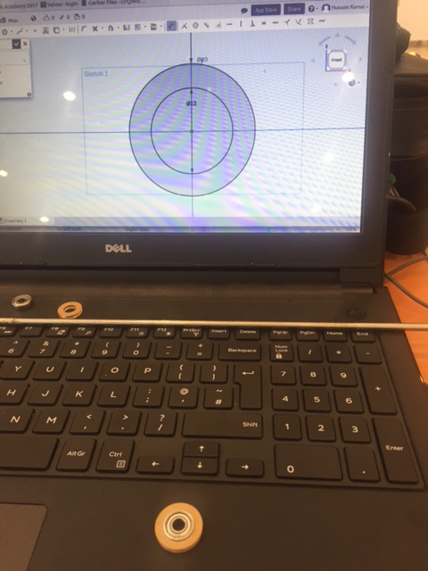
This image shows the acrllic bearing I cutted using laser cutting fitted into or metal rod thats holdingg the stepper motor.
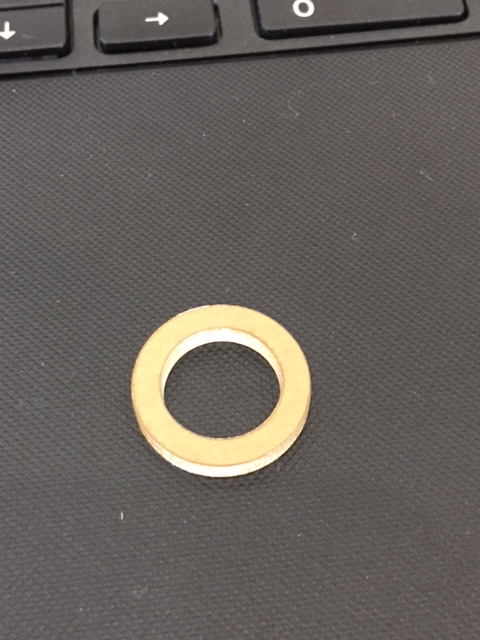
This image shows the cutted acryllic piece only.
This is a clear and accurate image that shows how the fitting is smooth and exact.
Finally , this image shows the use of my test that I mentioned above
Assembly :
I helped in assembling the whole project as shown below :
This image is when we I participated in the assembly of of our project without the frame.
Group Project Base Frame
Design :
Third I designed a frame to be cutted out from wood 18mm for the machine of our project as shown below :
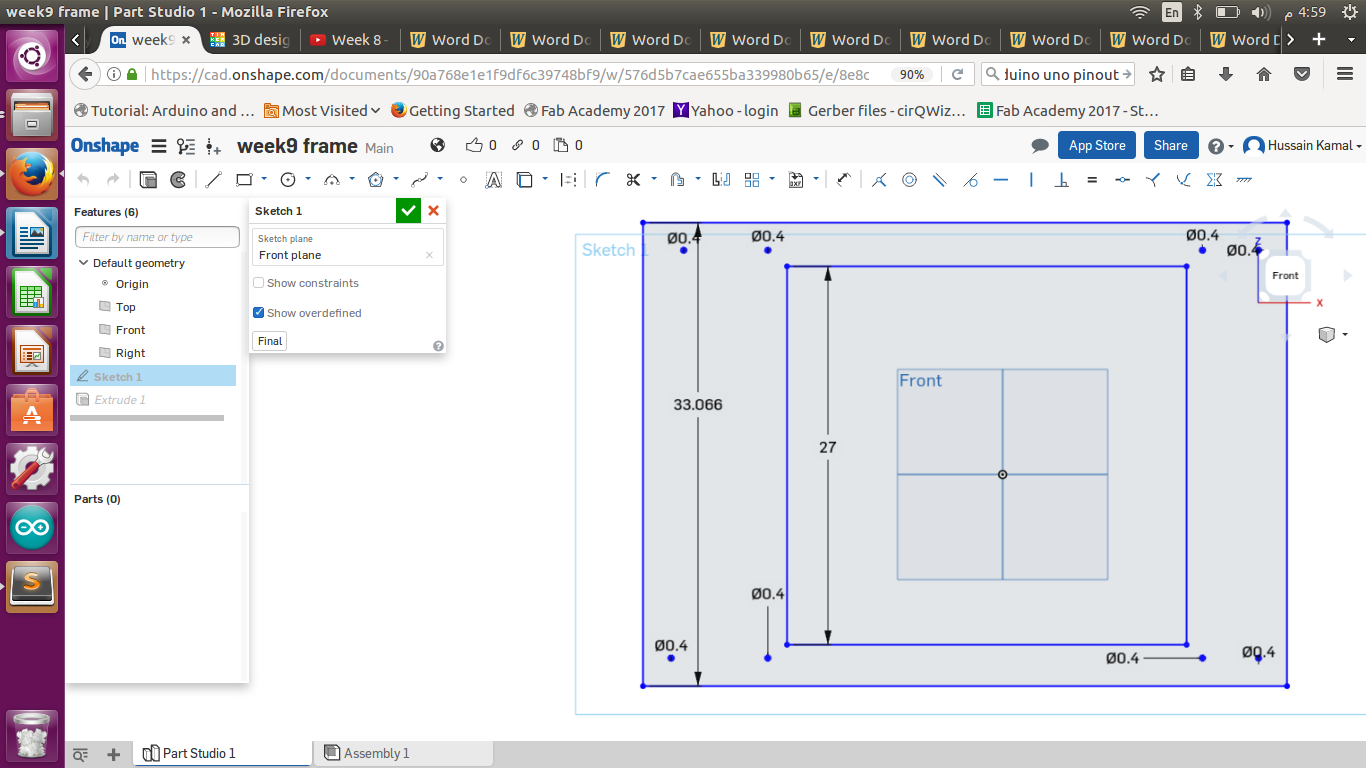
Above are the parameters I used to design the base , and of course I tookk accruate measurements of the places of the screws I had to fix.
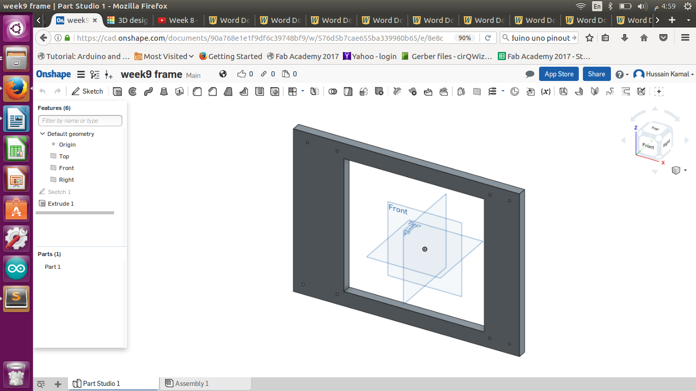
The above image shows my design after I extruded it by 18 mm (depth ofour wooden sheet)
CNC Machining :
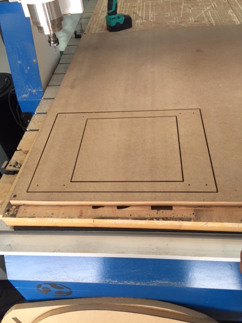
This was while I was cutting the frame.

And finally this was when I fixed our group project on the frame (base).
Rode Path
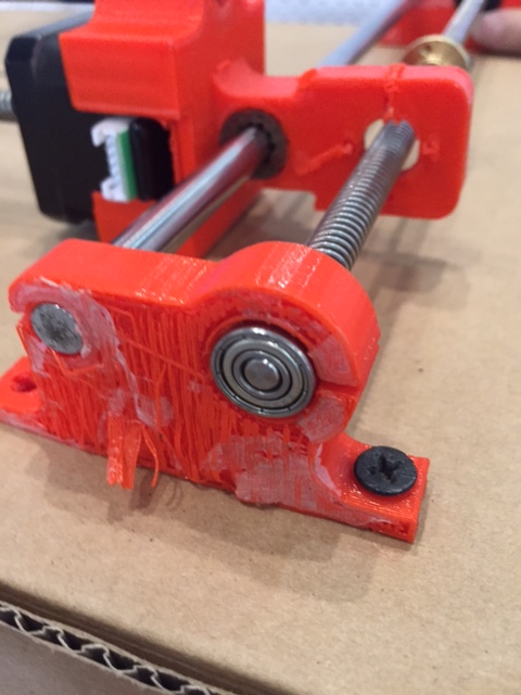
I also suggested and designed and printed the path board for the end of the rod in our group project to be attached to the frame , because when we turned the stepper motors on , it was loose and not moving due to the hanging metal rod fixed from one end.
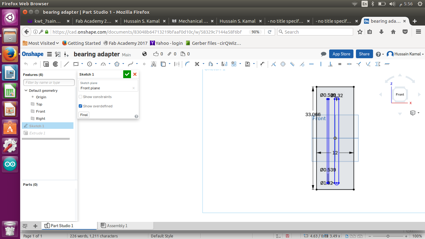
This is my design after I measured the fittings of the two rods so it would be a smooth path for them to move.
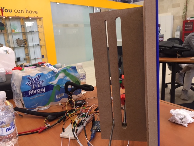
Above is after I cutted it out and fitted propery in our project.
I also participated in the wiring and programming discussions with my colleagues , and suggested many changes as we faced many mistakes like fixing a belt instead of what I suggested above to hold the end of the rod while dragging it up and down by the stepper motor, and also before the belt we designed 3d printed holders to hold the end of the rod but unfortunately also held the rod back while moving and stopped it from functioning in the right way. But my suggestion worked perfectly for the mechanism of our group project. I also printed many of our parts.
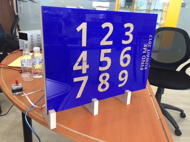
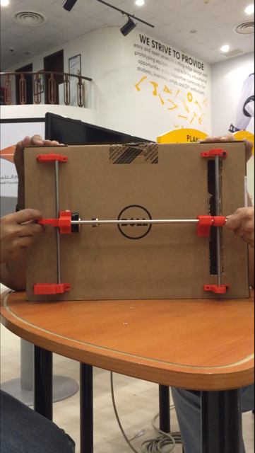
And this is what our final group project looks like