Electronic Design
Week 6
Assignment :
-
Redraw the echo hello-world board, add (at least) a button and LED (with current-limiting resistor), check the design rules, and make it.
Software
There are many softwares used to design electronic circuit boards like 123D design , Altium designer , KiCAD , and I used Eagle CAD to design my circuit board because it’s simple for designing. And after searching about Eagle, I found out that it is becoming a standard, and Open Source companies from Sparkfun to Adafruit use it religiously and have created high-quality libraries of parts and multiple tutorials. EAGLE is a scriptable electronic design automation application with schematic capture, printed circuit board layout, auto-router and computer aided manufacturing features. EAGLE stands for Easily Applicable Graphical Layout Editor.
Process
Adding Components :
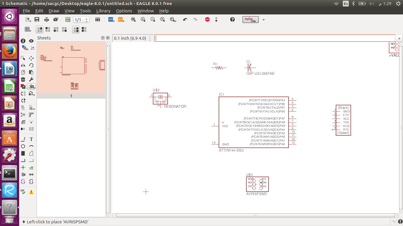
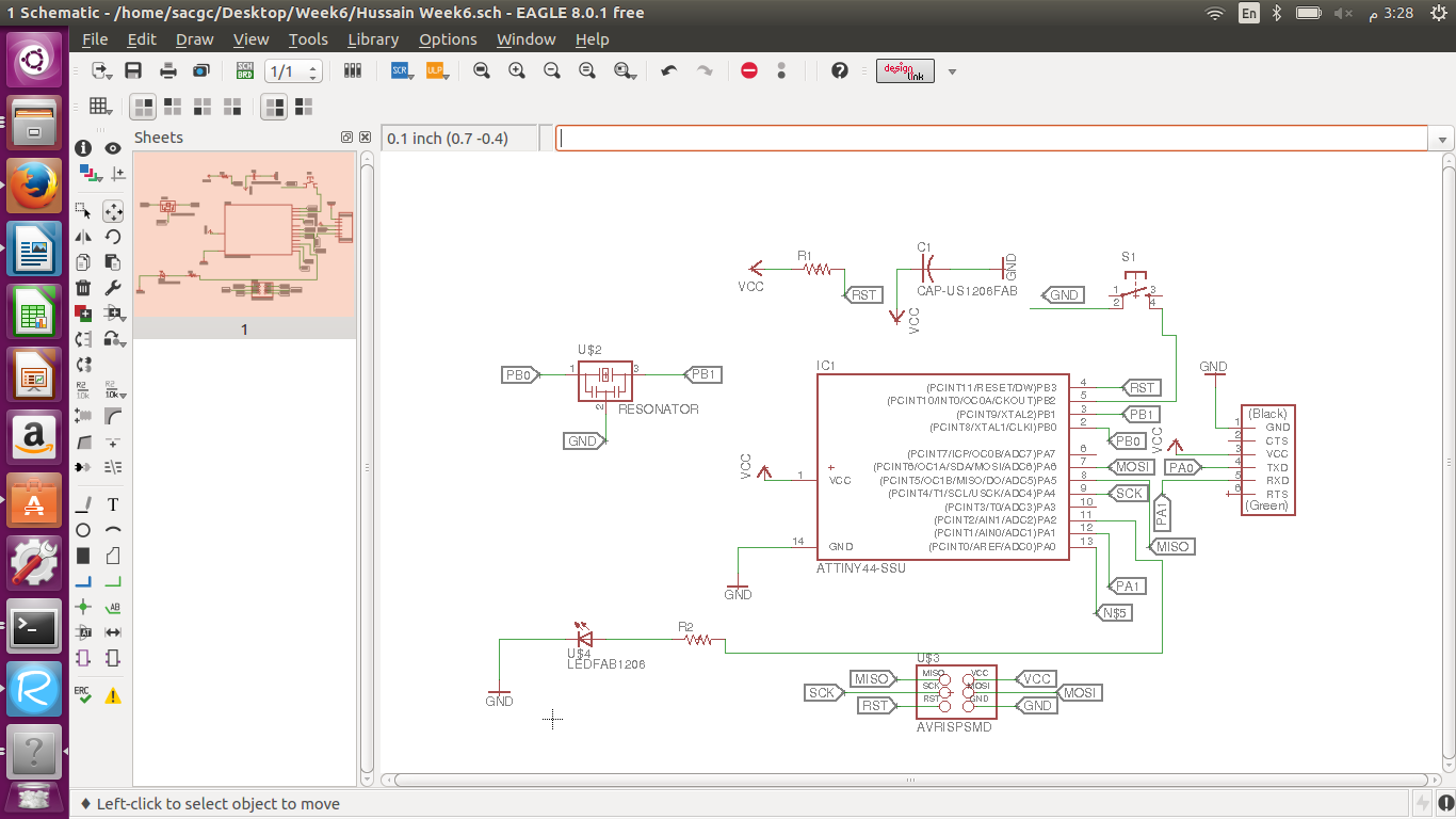
First I created a new file in schematic view (EAGLE contains a schematic editor, for designing circuit diagrams. Parts can be placed on many sheets and connected together through ports) , There is also board view. Then I downloaded the fab library from the fablab website because we are using 1206 components and opened it in Eagle CAD to add the components to my circuit board, and opened the image from fablab website tutorial for electronic design to know what components I need and connect which ones. Selecting the components after typing add was a little difficult because I had to see what some abbreviations mean so I know which components they were. I enjoyed it somehow.
Connecting/Labeling Components :
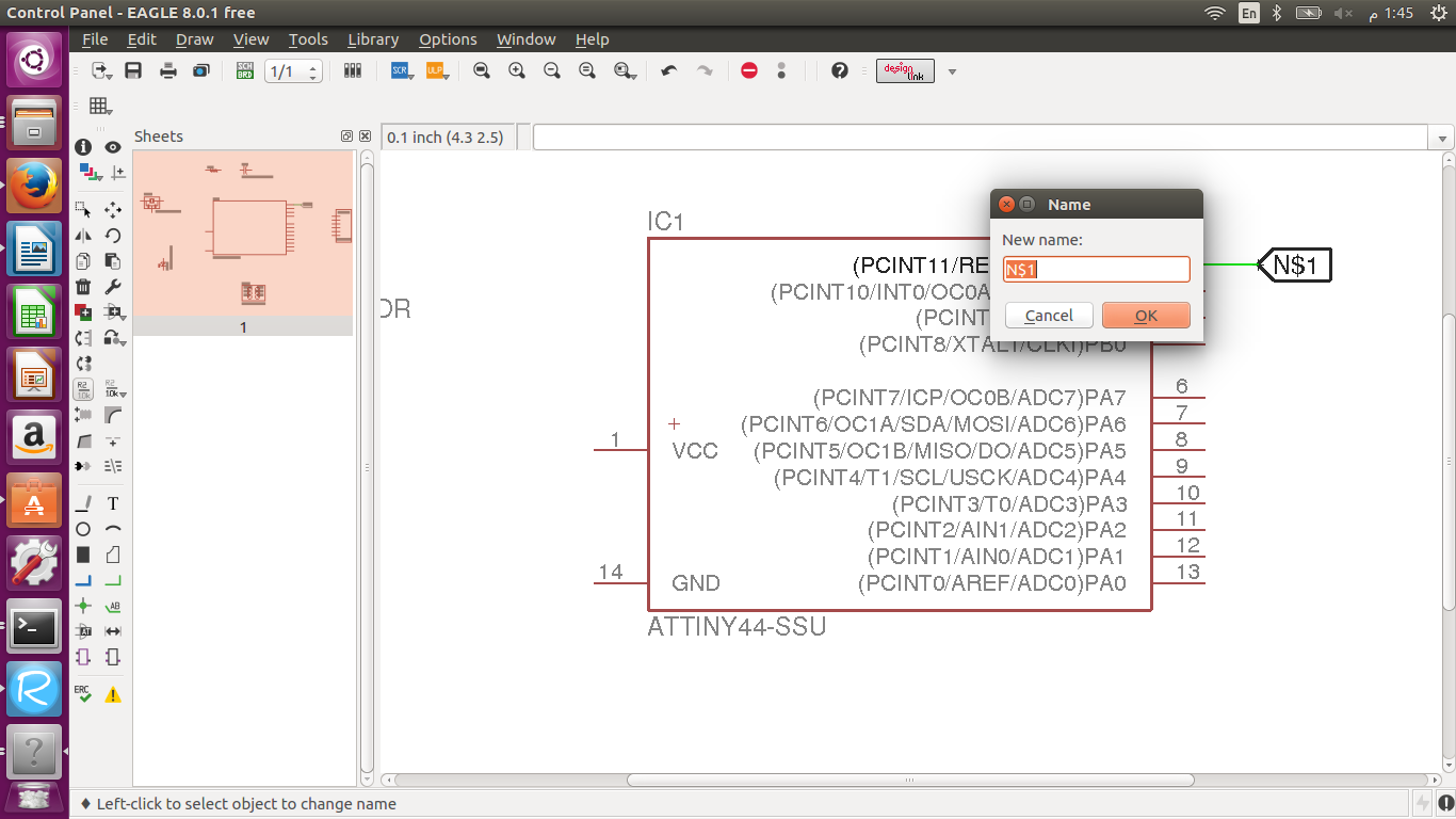
Second thing I had to do was labeling to connect the different components as needed and shown in the image from the tutorial, So after I added the components I used the net tool and label tool to label one component with specific characters by typing name in the address bar to rename the label and the other component that I wanted to connect with the same exact label in order for it to connect. Then I added the LED by connecting with a resistor to not fuse the LED bulb with too much volts and to the ground and I added the switch by connecting it to the ground. There is another way to connect the components with the net tool only and dragging the line between two components. Sometimes when I added a label to the component after using the net tool , it would not connect I don’t know why I just had to drag the label a little so it would connect , I think to overcome this problem I could have connected everything by the net tool only. To connect any component to VCC or Ground I could add them typing add in the address bar and adding them or label with the specific characters I already labeled them before.
Routing Circuit Board :
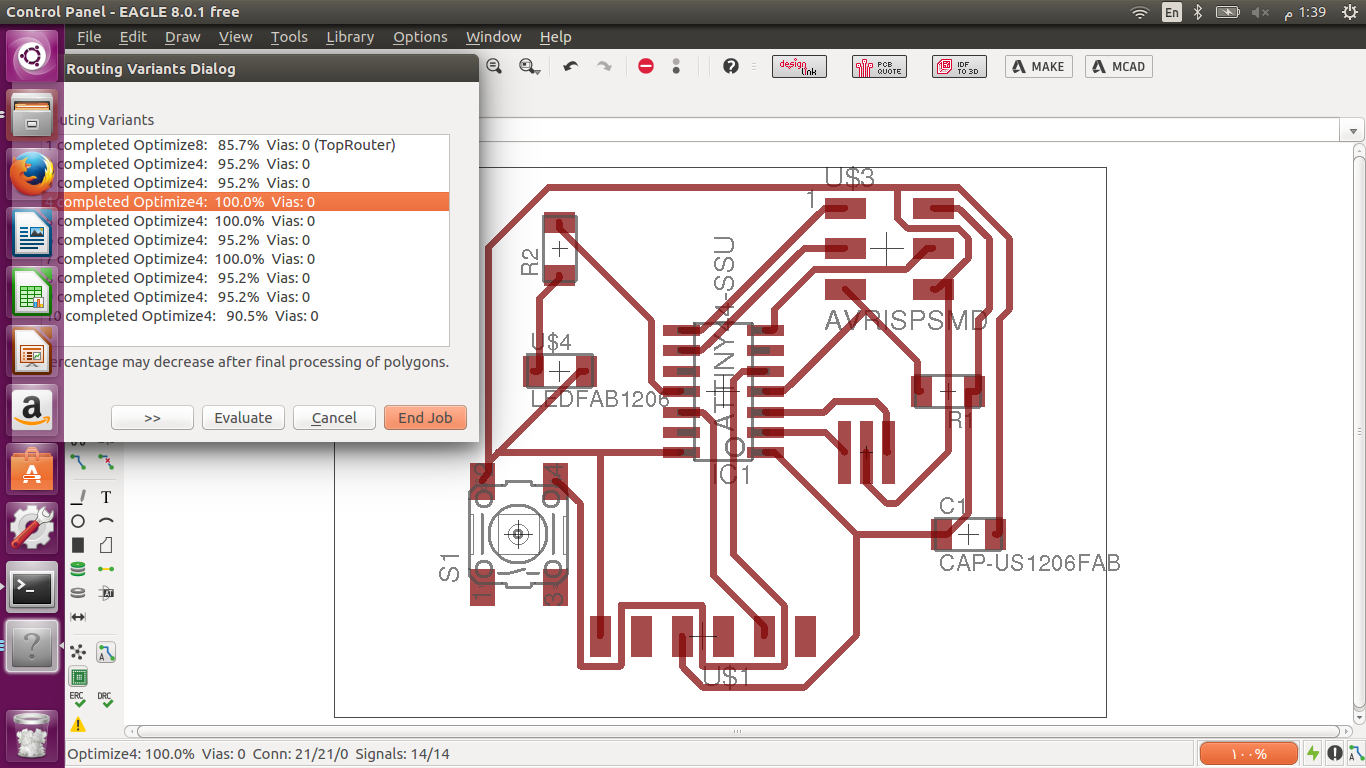
Third, after I finished connecting I had generate the file (switch to board) to route the components and avoid any overlapping. We can route in two ways Manually and Automatically. This is my first experience I’m a little confused for manual routing do I used automatic routing. I fixed the width of routing line to be 16 mm to avoid having shorts happening easily while circuit milling. I tried fixing the layout of the components many different ways and press auto-route and see if its possible and evaluate the different options so I know which component to move or rotate and had to type ripup; (for disconnecting routed traces) to again be able to change the layout after auto-routing, at the beginning it was hard whatever I did would not work because I kept the components close together, so I placed the components a little far apart and changed the layout again and again with rotating some components of course until finally I got 100% as shown below. I could also route manually
Printing my Circuit Board :
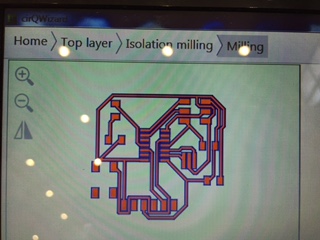
Then I saved the file as .brd and converted it to gerber format .cmp using and opened it in CirqWizard to print the circuit board on the copper sheet , as shown below.
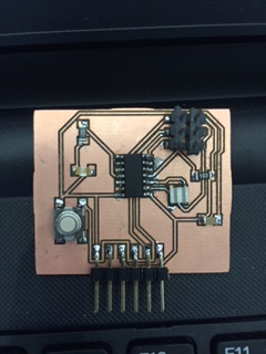
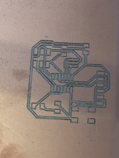
Then I printed the design on the copper sheet as shown below, after testing the depth and fixed the copper sheet.
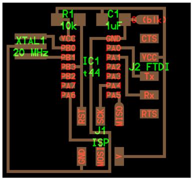
Components Used :
- Attiny 44
- Capacitor 1 UF
- Resistor 10 K
- FTDI SMD Header
- AVR ISP SMD header to program
- LED (1)
- Resistor 100 ohm
- 6mm tact Switch
- Resonator 20 mhz
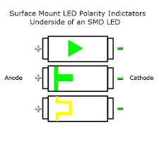
The LED component has polarities , so I looked it up to know which polarity each end is , as shown below it was the middle one , I connected the cathode side to the switch component and the anode side to the resistor component (100 ohm)
I chose the LED resistor 100 ohm because the resistor formula = IC Volt (5 Volts) – Forward voltage (2.8 Volts) divided by the Current (20 mA = 0.02 A). The LED bulb I used is (list – c230tbkt) , I got the resistor value 110, that’s why I used the nearest value of 100 ohm. I looked up the forward voltage and current from (Click Here)
Result :
Then I soldered the components to my board after having many difficulties in soldering , I wish there was an easier/simpler way to solder.