Electronic Production
Week 4
Tools Used :
-
I used Eagle Cad to convert into board file into gerber file
-
I used Cirquid for circuit printing
What I did :
Milling :
It was easy converting the file I downloaded David’s board from FABLAB website.
It was also easy cutting out the circuit board out of the copper sheet ,
First : I opened CirqWizard , then manual control then home so the bit pin goes to home destination , then change the bit to .25 to draw the circuit.
Second : I open the file I took from eagle cad through CirqWizard, then area of board will appear to select where to print the circuit on the copper sheet, then place the copper board on the Cirquid mini machine , then tested the board level (depth) (z-axis) by typing – 16 and pressing (reduce & test) till it touches the copper sheet and tests the depth on different parts of the copper sheet to check if the same depth should be printed, then pressed run, after that cleaning the circuit board after cutting and before cutting making holes on all lines of the board, the cut the board.
Below are some pictures of what I have done , ( I made more than 3 circuit boards due to my mistakes in z-axis depth )
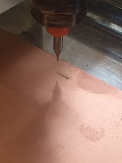
I was testing the z-axis depth here which was pretty confusing and difficult to decide which depth was right.
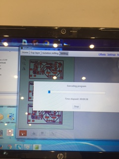
First I runned the design cut using a 0.025 bit to design my electonic board.
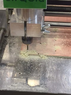
Above image shows the milling head drilling the copper board after cutting my design of course and changing the bit.
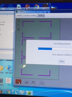
This was the final step I pressed run to cut out my board from the copper sheet.
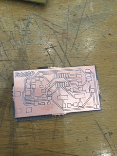
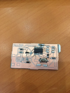
This was what my printed board looked like after I cutted it out.
Problems :
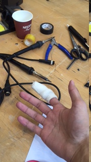
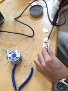
My difficulty was understanding the relation of the components because I am new to electronics and here is what I did while I was soldering the components of course it was extremely difficult because it was my first time and the size of everything is small , and I also burned myself by holding the metal part of the soldering tool and continued working while I was injured :
Mistakes :
Below are my two wrecked boards, one by using too much lead on the copper circuit board to solder the ATTINY44 , and the other I soldered too much the 10UF & the 0.1UF components.
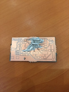
My first mistake I soldered a little bit of lead on the places of the pins of the attiny to easily put the attiny later and just apply heat so the lead would all melt and solder with the attiny pins , but unfortunately it turned out to be a mess lead got everywhere and ruined my electronic board and I had to do it again.
My second mistake is that I soldered too much lead while soldering the 10UF & the 0.1UF components which were my last two components to solder for completing the whole thing which was really frusturating.
Result :
Here is the third time that I had competed at last & programmed the circuit using below first four codes from fablab website that I typed using terminal avrdude / GCC software and dependencies:
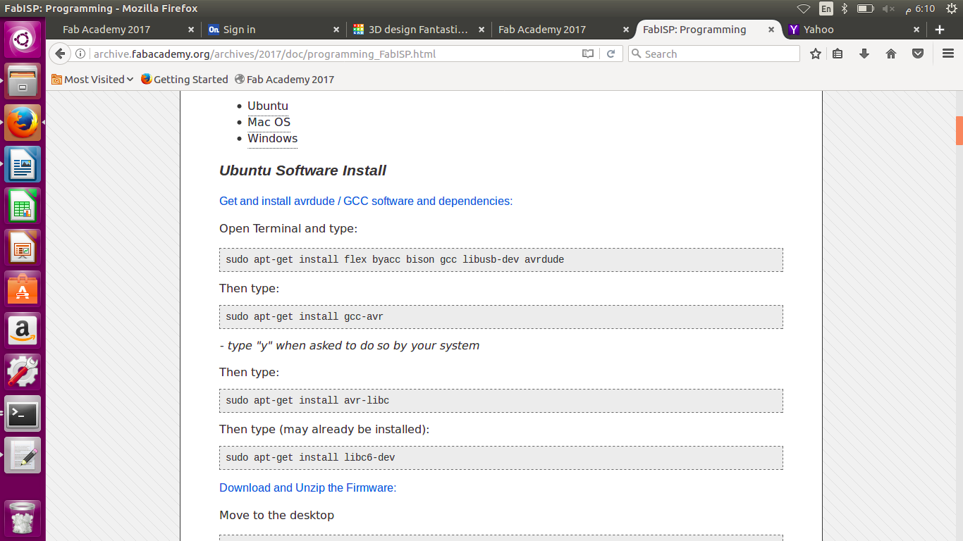
I used the above commands to install dependencies as required.
I downloaded the program file the I opened the terminal inside the folder and I used the below codes to program the isp :
- make clean then make hex to compile
- make fuse to set the fuse
- make program to program the board to become an isp
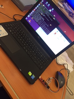
Then I programmed my board successfuly.
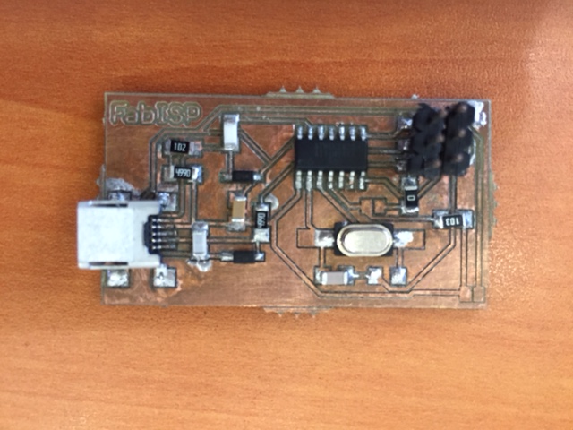
And this my hero shot of my board