FINAL PROJECT - DESIGN
CONTENTS
Click on any of the links below to see further details about the final project.
- Project management: Checklist of the project's gradual development.
- Concept: General draft of the first conceived idea.
- 2D/3D design: Summary and steps of the design process.
- Electronic production and design: Details, design and production of the main board for the project.
- 3D printing, laser cutting and prototyping: Further details about the production of the robot's parts.
- Embedded, application and interface programming: Networking, motor control and web interface.
- Final project summary: Video demonstration, bill of materials, files of the final robot and general summary.
DESIGNS SUMMARY
This page contains the iteration of design ideas for the project. Click on links below to see in more detail.
Tracks v1.0 - First attempt to design modular tank tracks and driving gear.
Tracks v2.0 - Second attempt to design modular tracks with a driving sprocket.
Robot body v1.0 - Housing box for the boards and stepper motors. 3 versions for Nema17, Nema14 and Nema11.
Robot body v2.0 - Design of 3D printable frame.
Pan and Tilt frame - Designed inspired from fbuenonet from thingiverse.
TRACKS V1.0
The following design was done with minimal knowledge of fusion 360 and mechanical design. It was a good learning experience.
TANK TRACKS v1.0
After careful consideration, Fusion 360 is going to be used to create a parametric design for the tank treads.
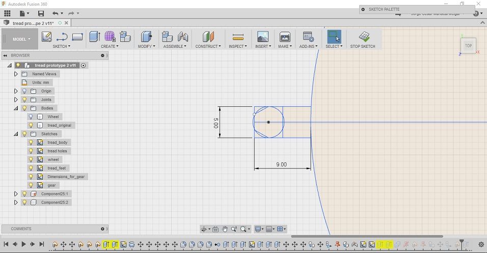
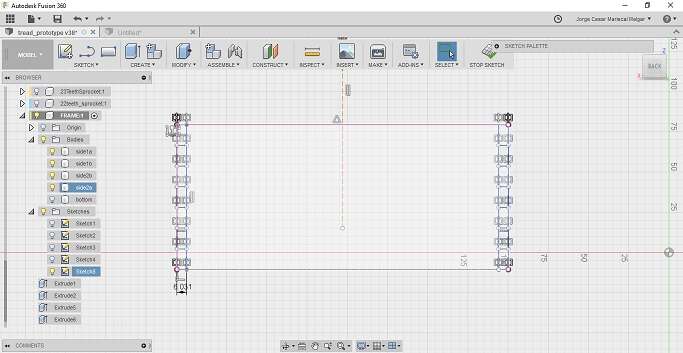
First, in the MODEL tool panel, a new sketch is created on the x-y plane.
I want the treads to be parametric as possible.
The next step is to extrude the 2D drawing. To do this in Fusion 360, use the e hotkey. I do several extrusions for the different parts. The extruded piece will look like this:
Next, I navigate to the bottom of the extruded part and create another sketch on the plane surface of the piece. Proceed to draw the bottom part of the tank tread.
Extrude the pieces to desired dimensions.
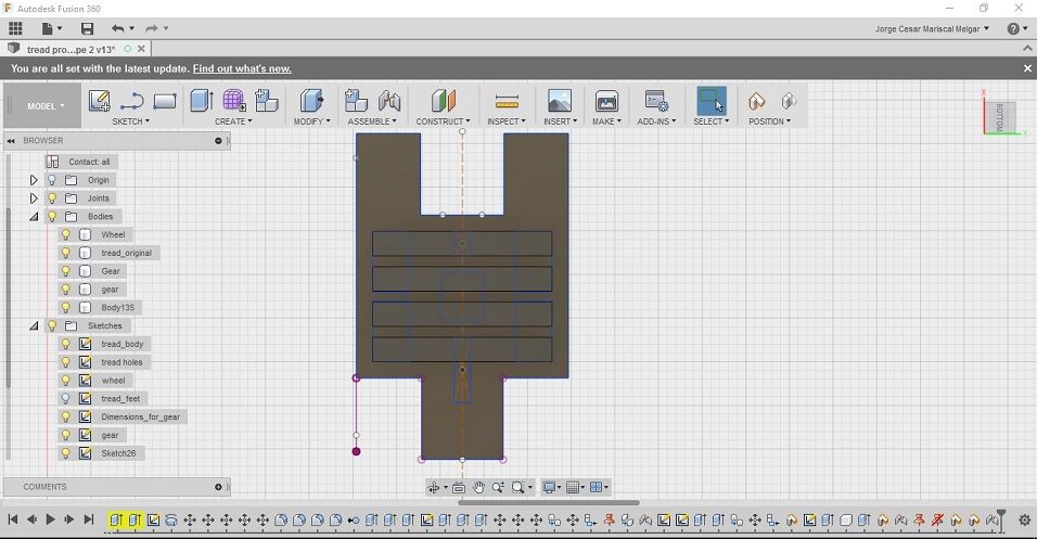
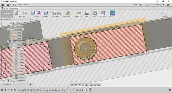
Turn the piece to the front view to design holes for the piece. These holes will allow to join different treads together.
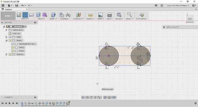
Create a new sketch on the front plane of the working piece and draw two circles with respective constraints.
A rough picture of the final extruded piece:
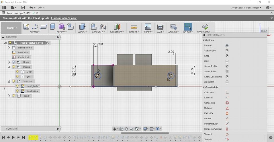
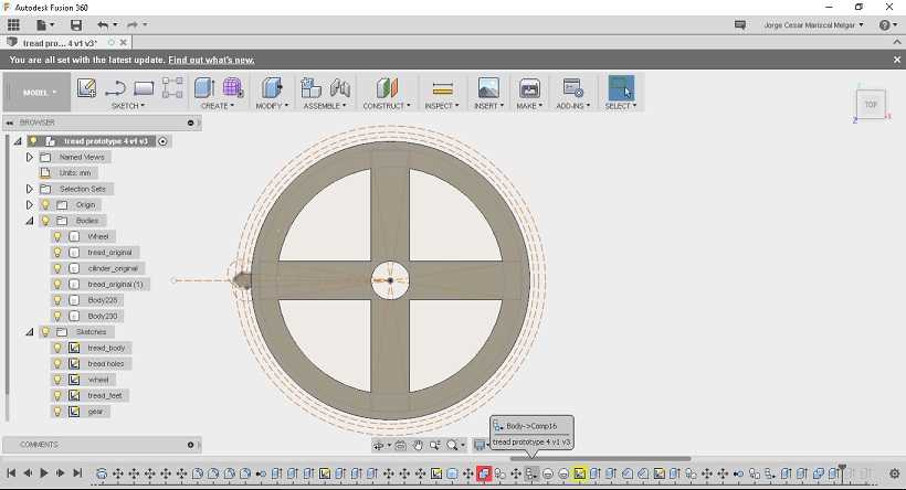
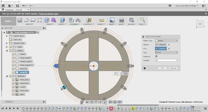
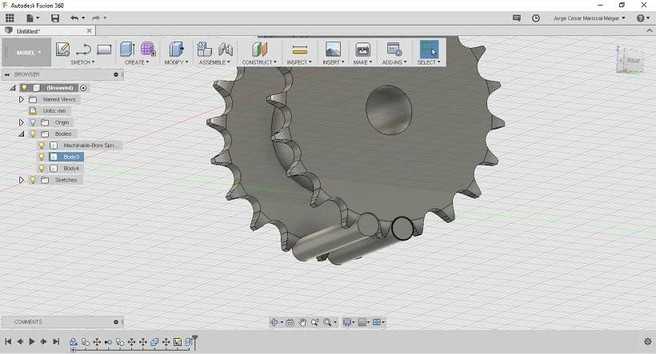
DRIVING GEAR - v1.0
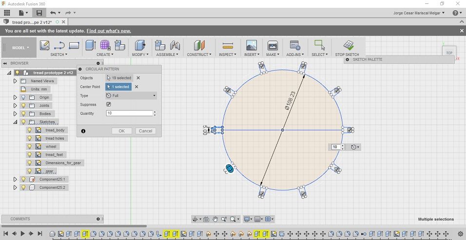
A driving gear is designed for the tank-tread system as traction support.
First, the distance between the track-spaces is measured and distance between each of the gear teeth is calculated.
A circle is drawn with the appropriate circumference.
Next, the teeth is designed to fit the depth of the hole.
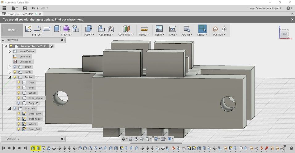
Fusion 360's circular pattern is run with 10 repetitions around the center of the circle.
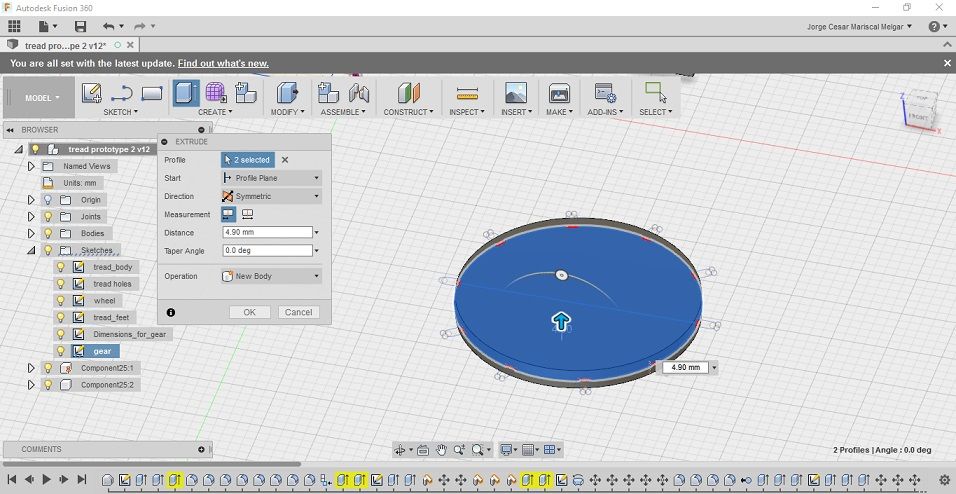
The bigger radius is extruded symmetrically 4.9mm.
Next, the teeth are extruded, according to the dimensions of the hole, also symmetrically.
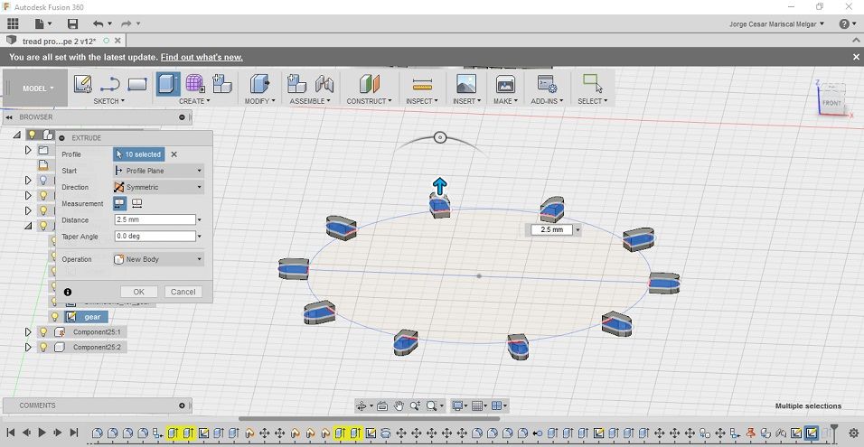
The new solid will look af follows:
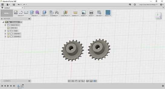
DRIVING GEAR V1.1
The limitations of my previous design were clear; a gear needs certain construction to be able to drive the treads.
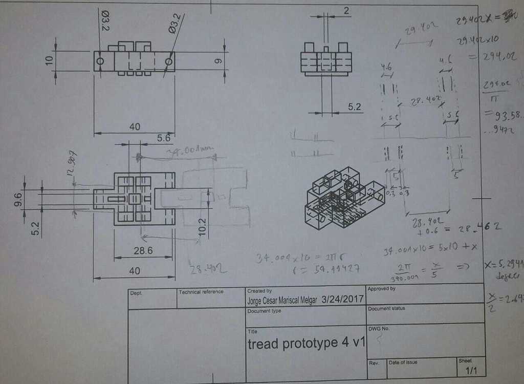
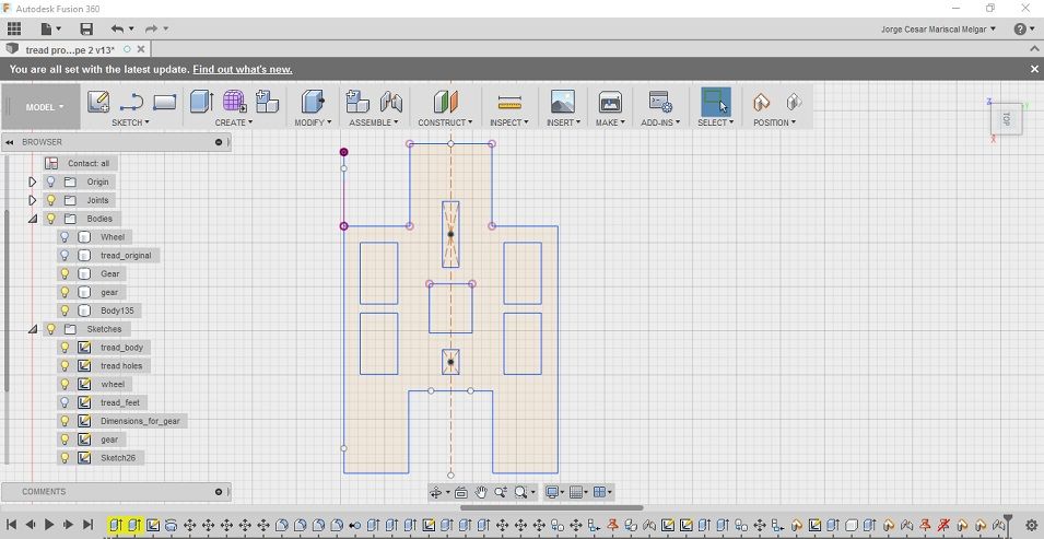
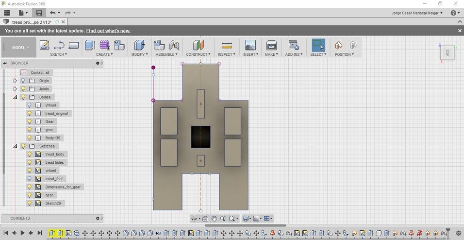
Treads are re-designed for better traction and smoothness.
I followed the construction lines outlined in 'Engineering drawing design by Madsen and Madsen'
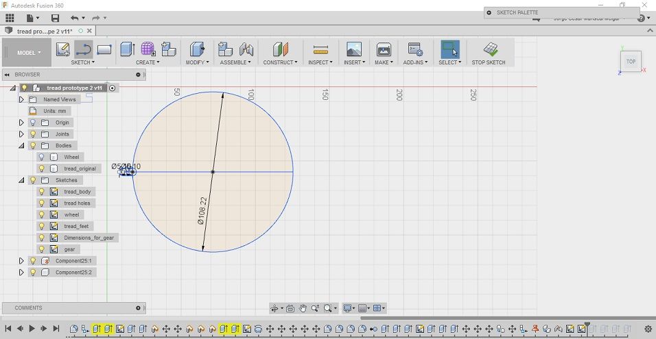
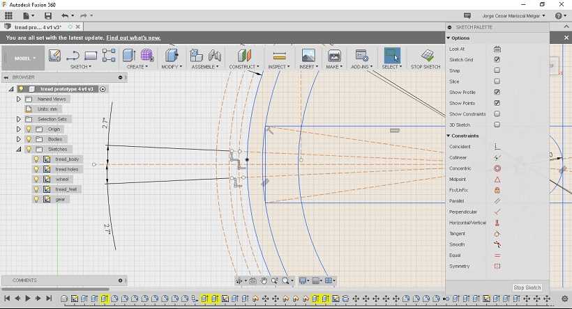
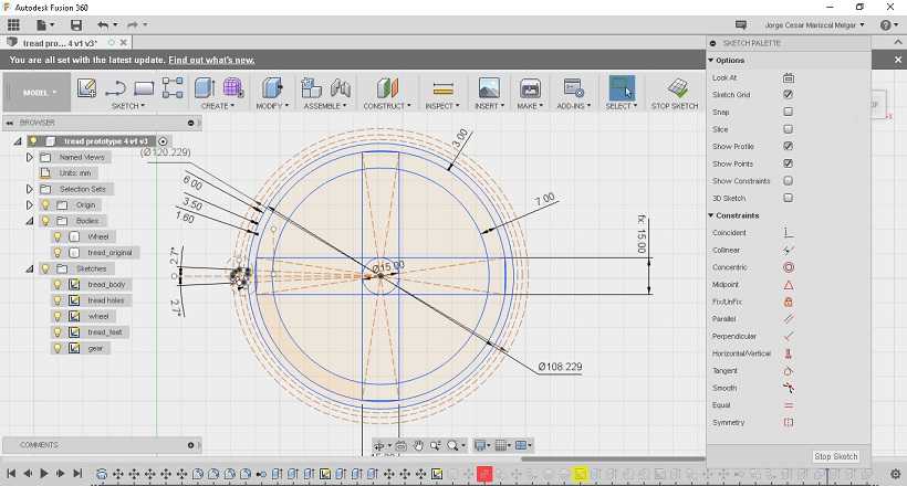
First, I create two construction lines to outline the size of the gear.
Also, 3 offset circles to draw the pitch diameter.
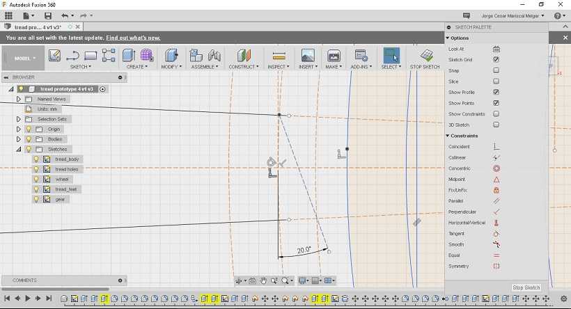
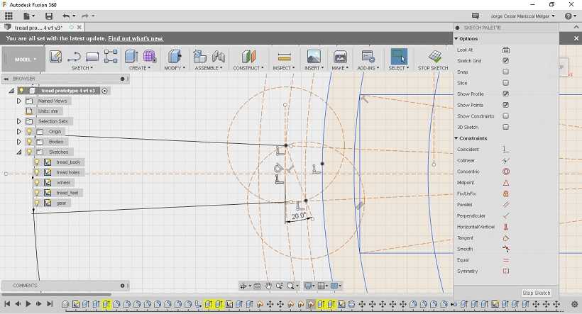
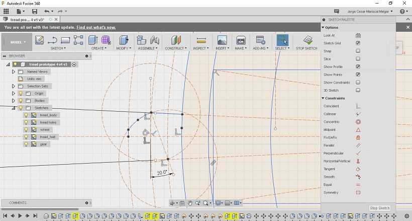
A point is drawn in the intersection of the middle circumference and another construction line with 20 degrees angle.
Two circles with equal diametre are drawn, one intersecting the other at the middle point.
Extra points are added:
Gear is drawn.
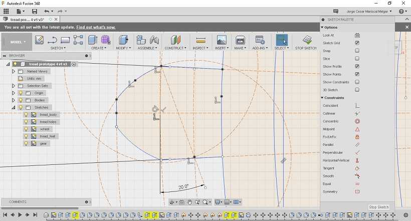
Final construction:
First extruded part:
Extrude one gear:
Create a circular pattern to fill the circumference with equally spaced teeth.
TRACKS v2.0
A lot was learnt during the design process and 3D printing of parts.
I decided to re-design the tracks after studying more about track-driving systems..
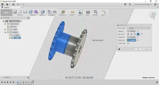
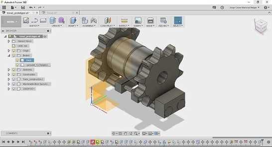
First, design a sprocket and created a copy.
Next, move one of the bodies towards the other, to form a driving sprocket for the tank tracks.
Draw two cylinders at the base of the driving sprocket.
Create a new sketch on the cylinders.
Preliminary part looked as follows:
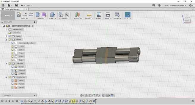
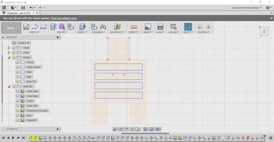
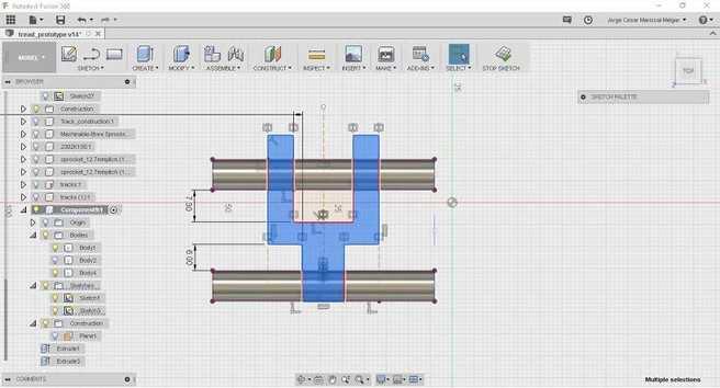
Next, use top view to skech the body of the tank track and create a copy to design the connecting link.
Create a new plane by offset and draw a smaller cylinder to link the two tracks.
See how the sprockets fit snughly.
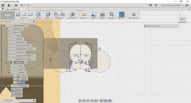
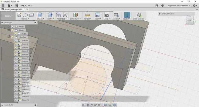
Next, I design the dimensions of the floor of the tracks.
As this is a prototype, links would be attached together with a 'hook', sketch the link hook as follows:
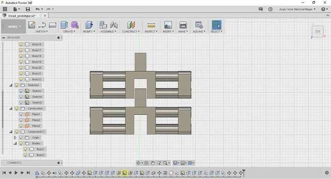
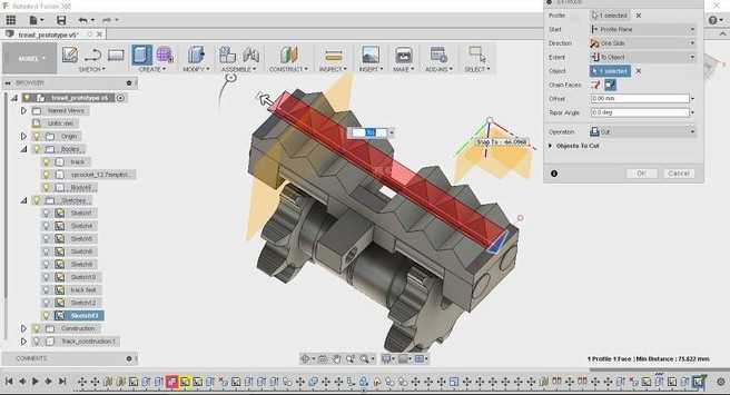
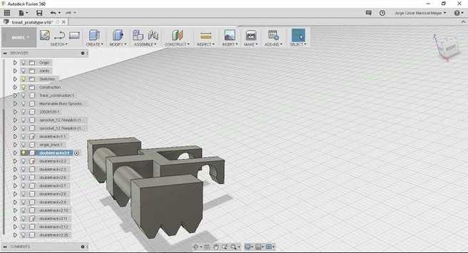
Next, create copies of the tracks and align accordingly (I used the assembly tools for joining tracks together).
After careful consideration, as my prototyping method will be 3D printing, I decided to reduce the size of the tracks.
I followed a similar procedure as above.
I also redesigned the hooks, accordingly.
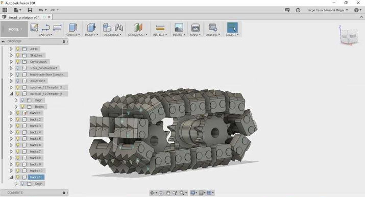
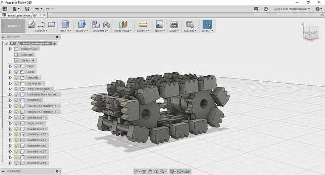
The final track looks less bulky and would be good enough for a prototype.
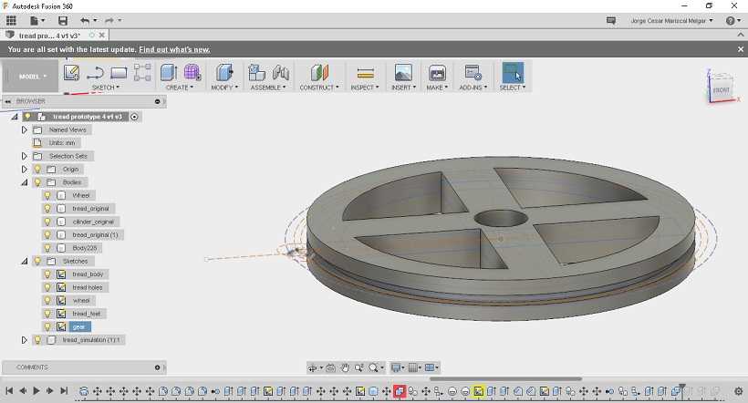
Final assembled design:
ROBOT BODY v1.0
Nema17 6mm thickness stock material
A simple box teeth for laser cutting is created using fusion 360 for a 6mm thickness stock MDF material.
First four sides of the box are created using simple extrusion.
Next, a sketch is created on one of the sides. Use the rectangular pattern tool to get the slots.
After slots are drawn, extrude and cut two opposite planes.
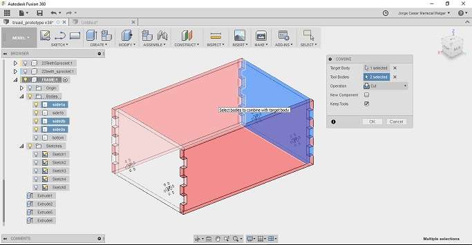
This is followed by any extra details, in my case, I design and extrude circles that will help mount the stepper motors and shafts of the sprockets.
Frame is exported into draftsight for laser cutting:
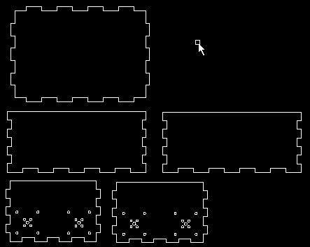
Nema 14 with 3mm thickness stock material
Same box is designed to fit a Nema14 motor and laser cut stock material of 3mm thickness.
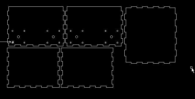
4mm thickness top camera mount
Top of the body is designed similarly and exported as dxf format intor draftsight.
ROBOT BODY v2.0
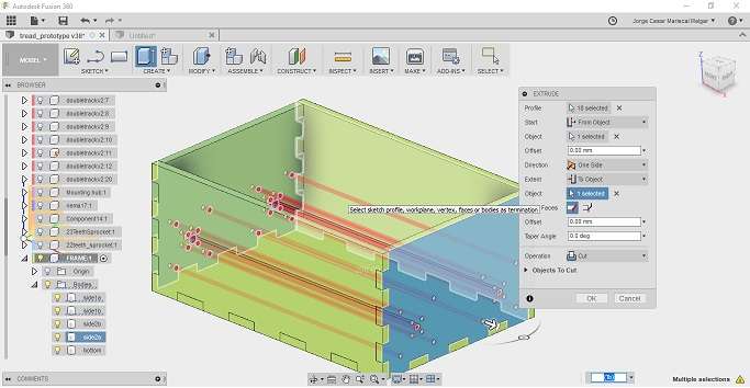
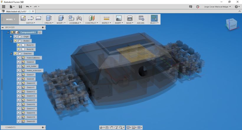
A 3D printed body is designed using Fusion 360.
First a lipo 3s battery is imported into the design, as well as a 9V battery. Next, the necessary spacing for the batteries is drawn using the drafting tool.
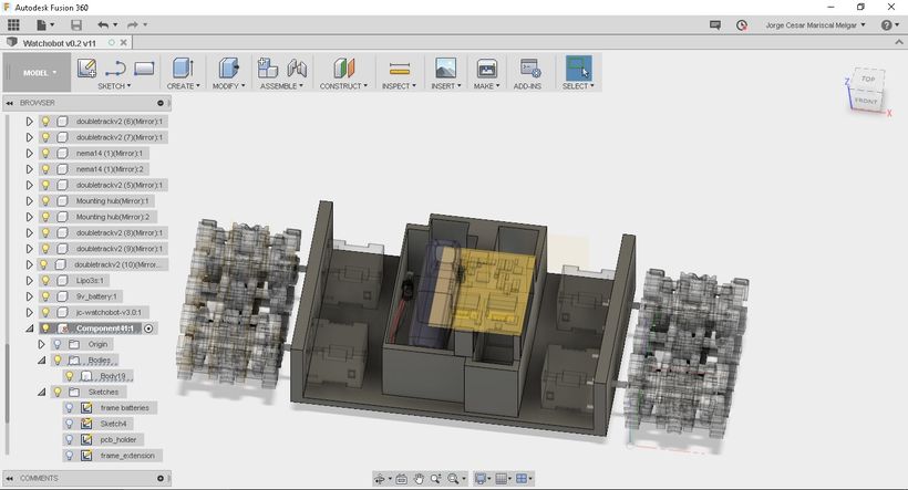
An arc is drawn to close the robot frame and give it a more modern look.
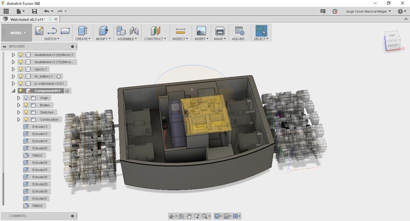
An offset plane is drawn and the loft tool is used to extend the faces.
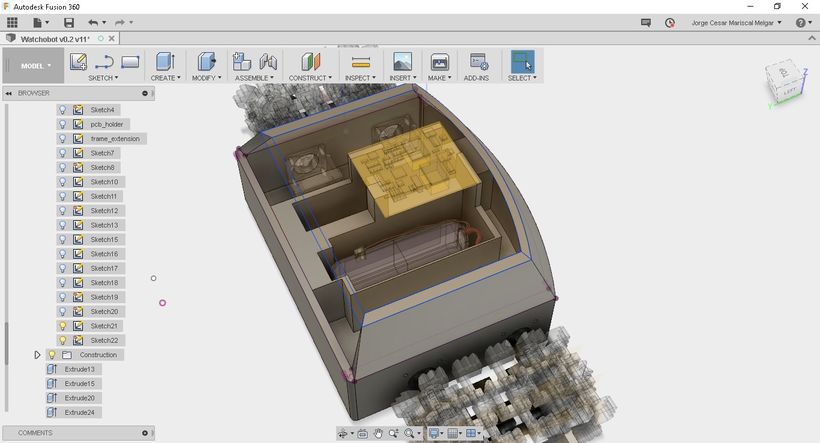
The step is repeated several times to obtain the top which will later hold the pixy camera module.
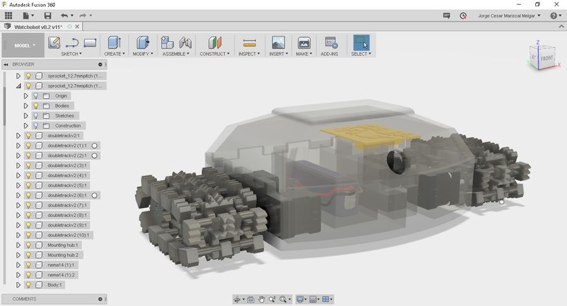
Design looks neat and is almost ready for 3d printing.
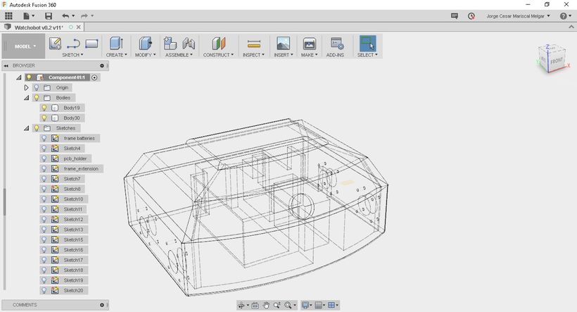
Wireframe of the drawing shows more details.
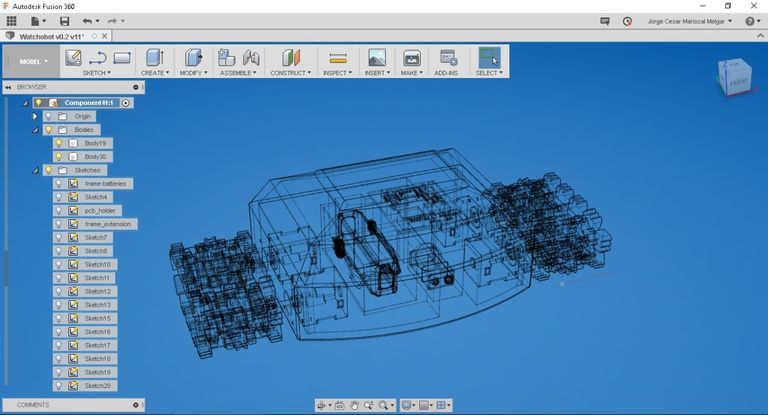
Finally, some joints are added and the body split into two, so it can be printed in two parts.
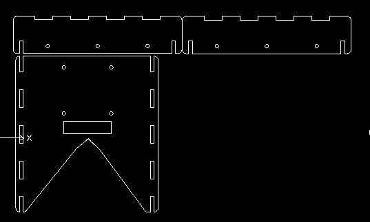
PAN AND TILT FRAME
Fbuenonet's mini pan and tiltis used to control the camera with two servo motors.
FILES
4mm thickness top camera mount
Robot body v2.0 printer friendly