
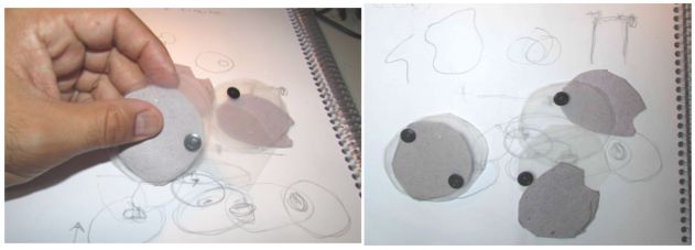
- Experimental process to get ideas.
To explore new ideas I worked with paper, plastic, scissors, hand draw and thumbtacks. This “hands on” process, before the digital drawing, helped me to reach the decision that was to work with circles that would be part of a kit dedicated to create organic shapes.
- Cutting with a vinyl cutter
After having an objective in mind, I explored free drawing using FreeCAD in order to fabricate with a vinyl cutter. The material I used was white paper (280g/cm2) and the machine was a vinyl cutter (Silhouette cameo). My aim is to work with FreeCAD to draw forms to cut in a vinyl cutter and test it.
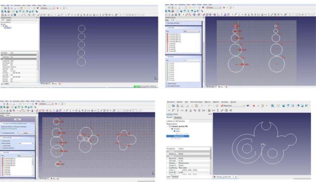
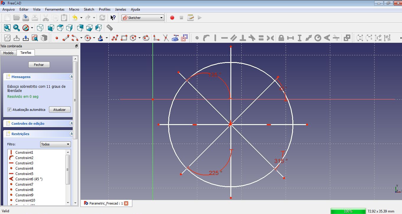
The Freecad process that I did was not parametric because I was just testing (see picture above):
- To Draw circles;
- Clone the circles and combine them in one shape / Apply constraints in each circle / Change the parameter radius by the constraints until you reach to a goal;
- Copy the shape and adapt it to be assembled/creating connections to fit together the parts. )
- Cutting it with a Vinyl cutter
First I needed to export the file from FreeCAD (.dxf) so I could open it in a Silhouette vinyl cutter software. To fabricate the piece I used a 30cmx30cm paper using this configuration:

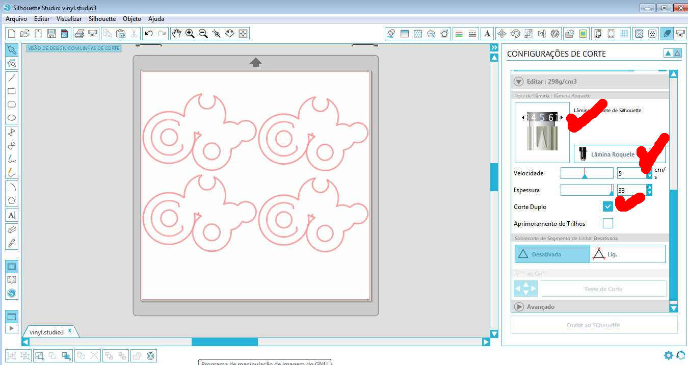
Vinyl cutter configuration
Vinyl cutter configuration to cut paper 280g/cm2.
- Velocity: 5cm/s;
- Blade level: 5;
- Double cut.
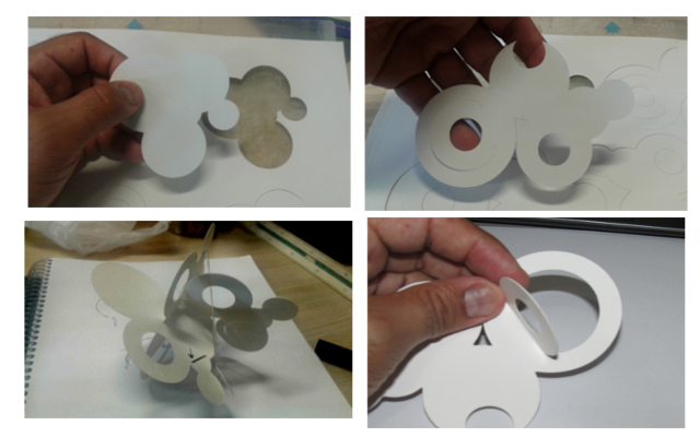
The shape fabricated in paper (280g/cm2) had 15cmx10cm and was helpful because it made me explore connections. The next step was to work on this shape parametrically using FreeCad and laser cut the final result.
Testing vinyl cutter
- Redesign parametrically and simplifying it with FreeCad
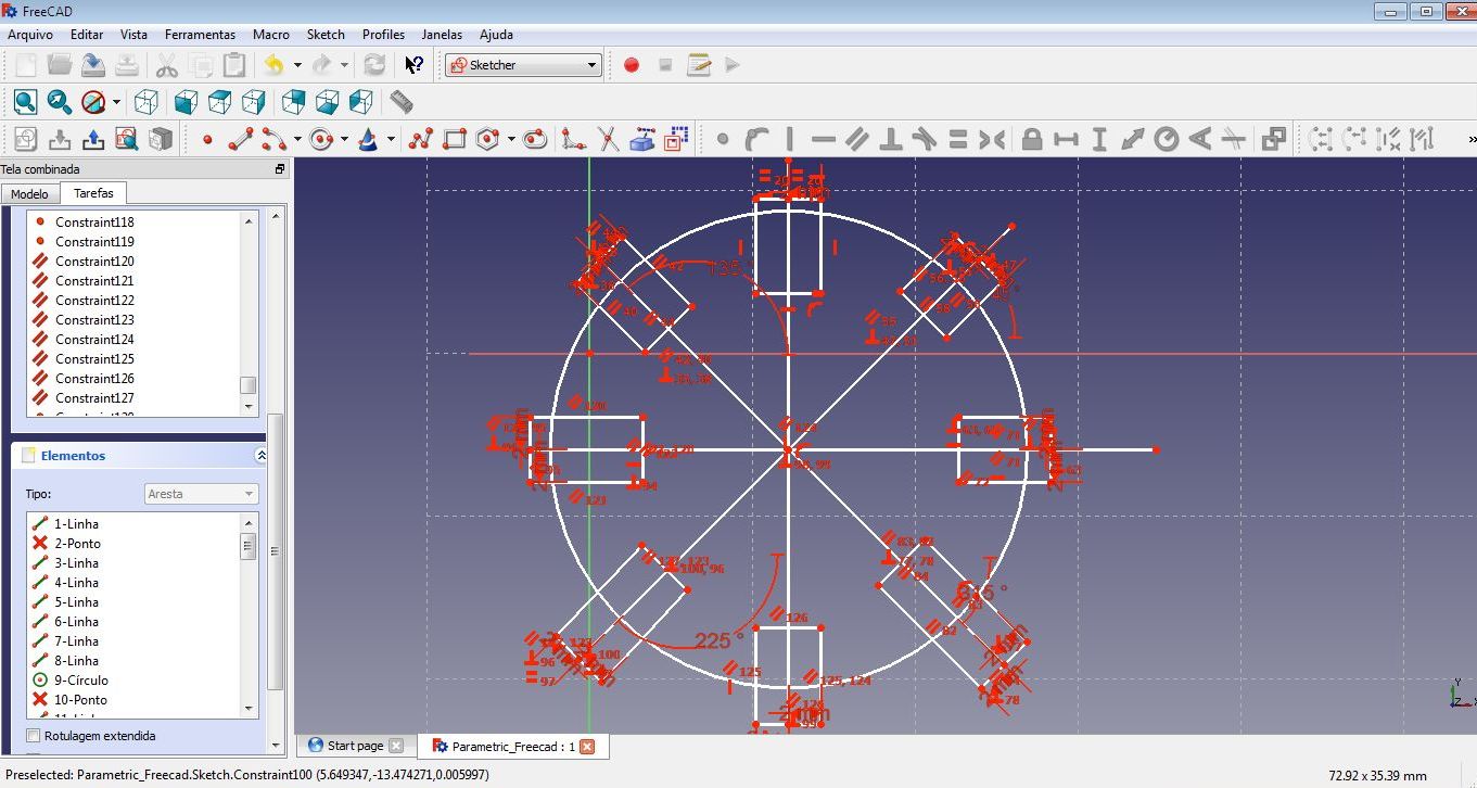
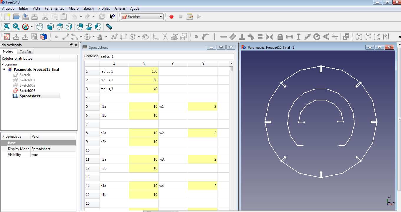
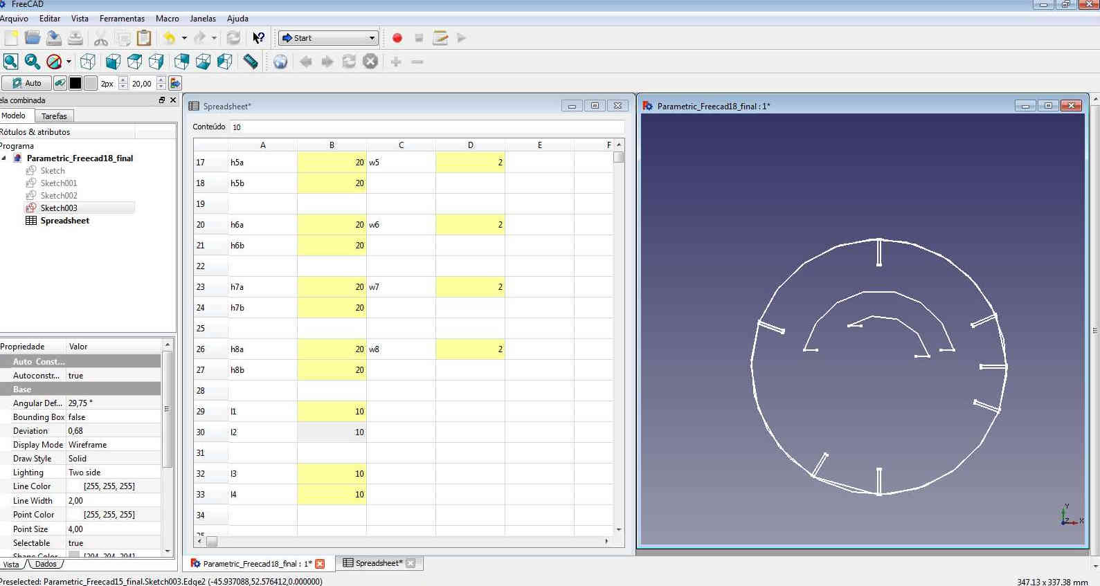
After an exploration with FreeCAD (to design the initial form) and with the vinyl cutter (to produce the first prototype), I redesigned the resulting shape so it could be parametrically adjusted and later on exported it to be produced with a laser cutter.
To draw with FreeCAD first you have to design the shape and after that assign constraints to each line. Constraints are used to limit the degrees of freedom of an object.
To use Freecad parametrically I used this tutorial FreeCAD spreadsheet/parametric design, and the Spreadsheets.
It is possible to use data from the construction in the spreadsheet, then link parameters to the shape.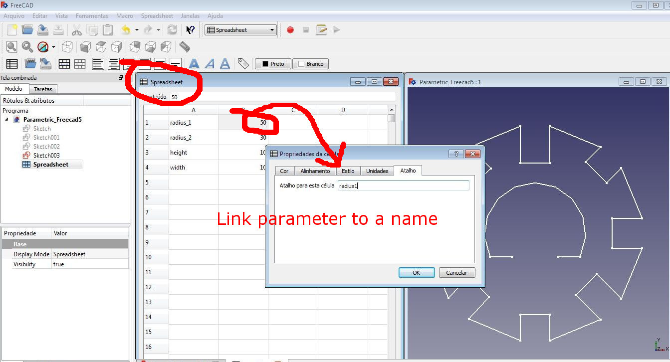
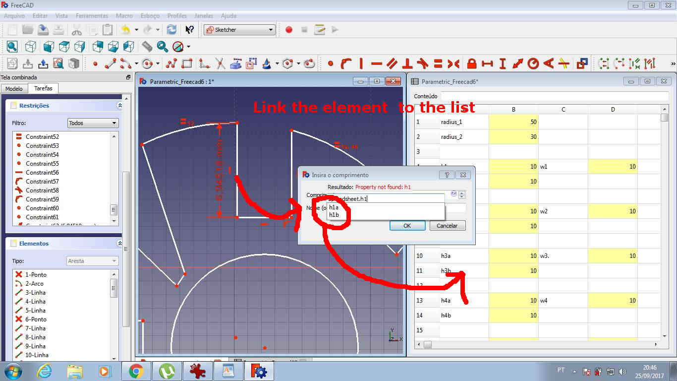
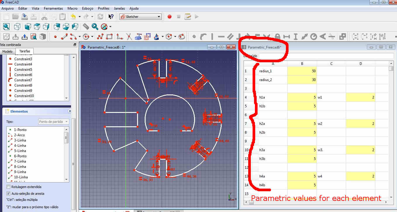
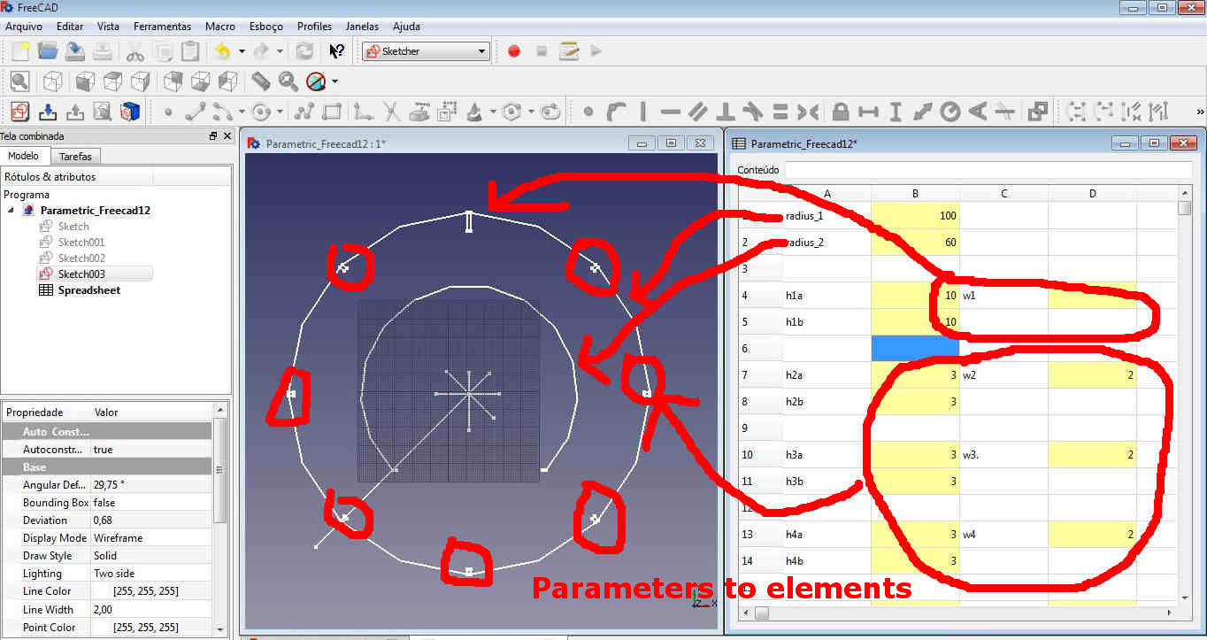
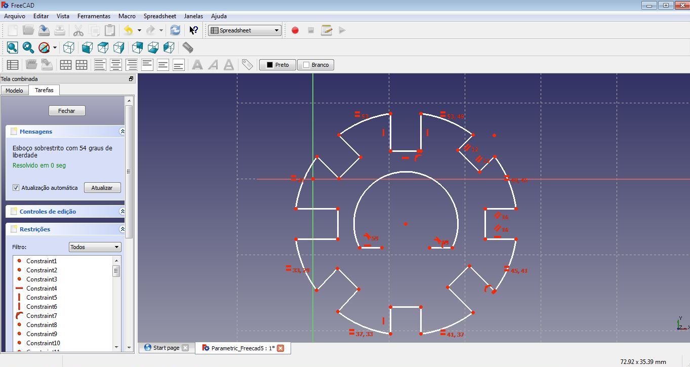
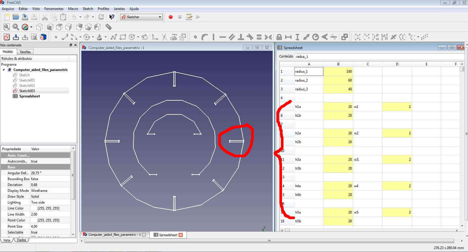
The final shape and the parameters
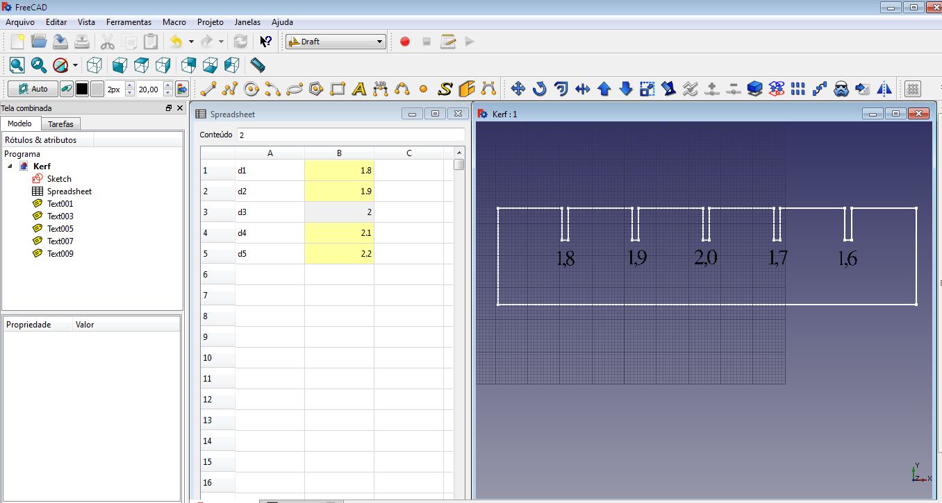
And then I did the kerf in the same way .
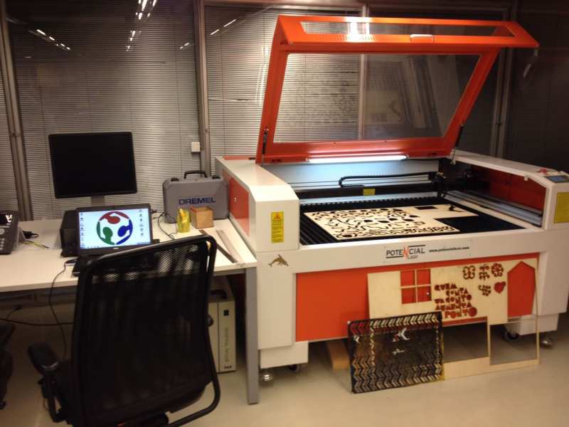
- Fabricating with laser cut.
To fabricate the shapes, I used the Porto Fab Lab ´s laser and RDWorks software.
Width carddboard
First I tested three configurations to cut the 1.8 – 2.0mm (width) cardboard. I cut the Kerf using the configurations changing the laser "power" (10, 20, 40) with the same velocity (40) to test the right configuration for the laser effectively cut the material.
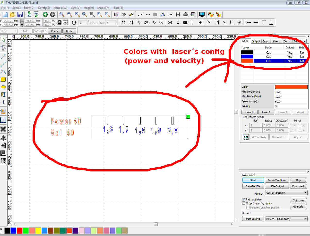
RDWorks CAM software
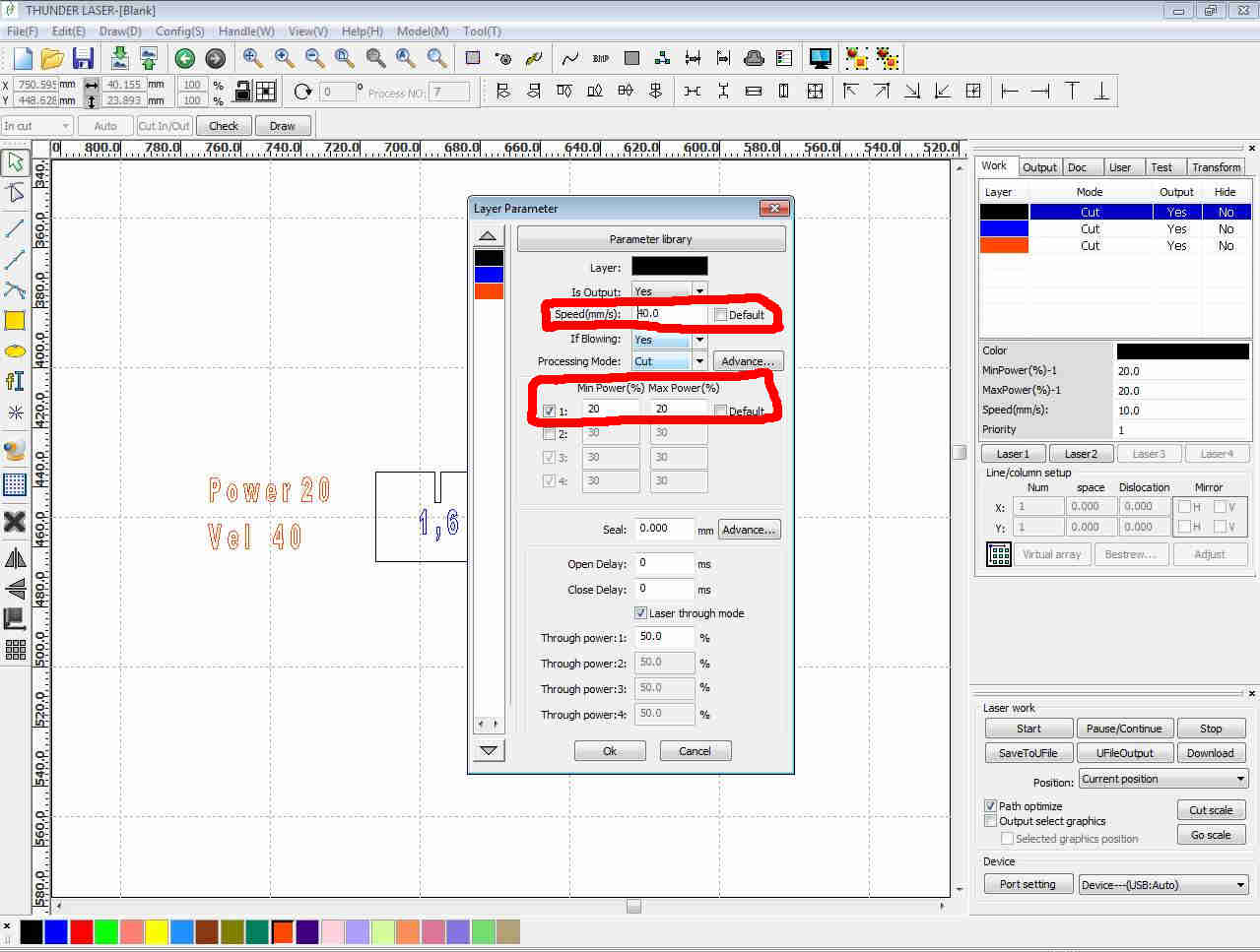
Changing the parameters CAM software
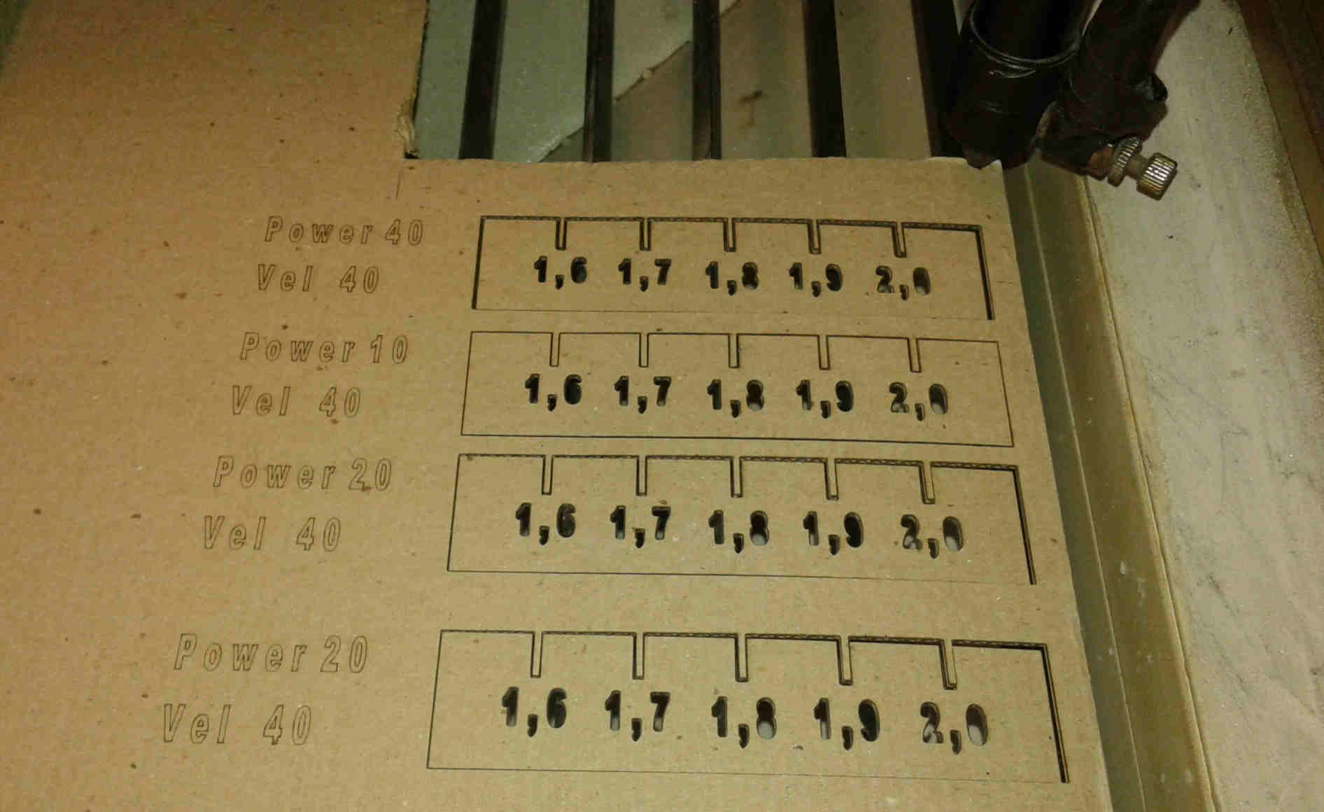
I realized that the material reacted differently toward the three laser configuration for power that I tested. Power "40" was too high, "10" was too light that not cut the material . Then the "20" level was the best.
All this three experiments were conducted fixing “40” as the velocity of the laser.
The powers tested with cardboard
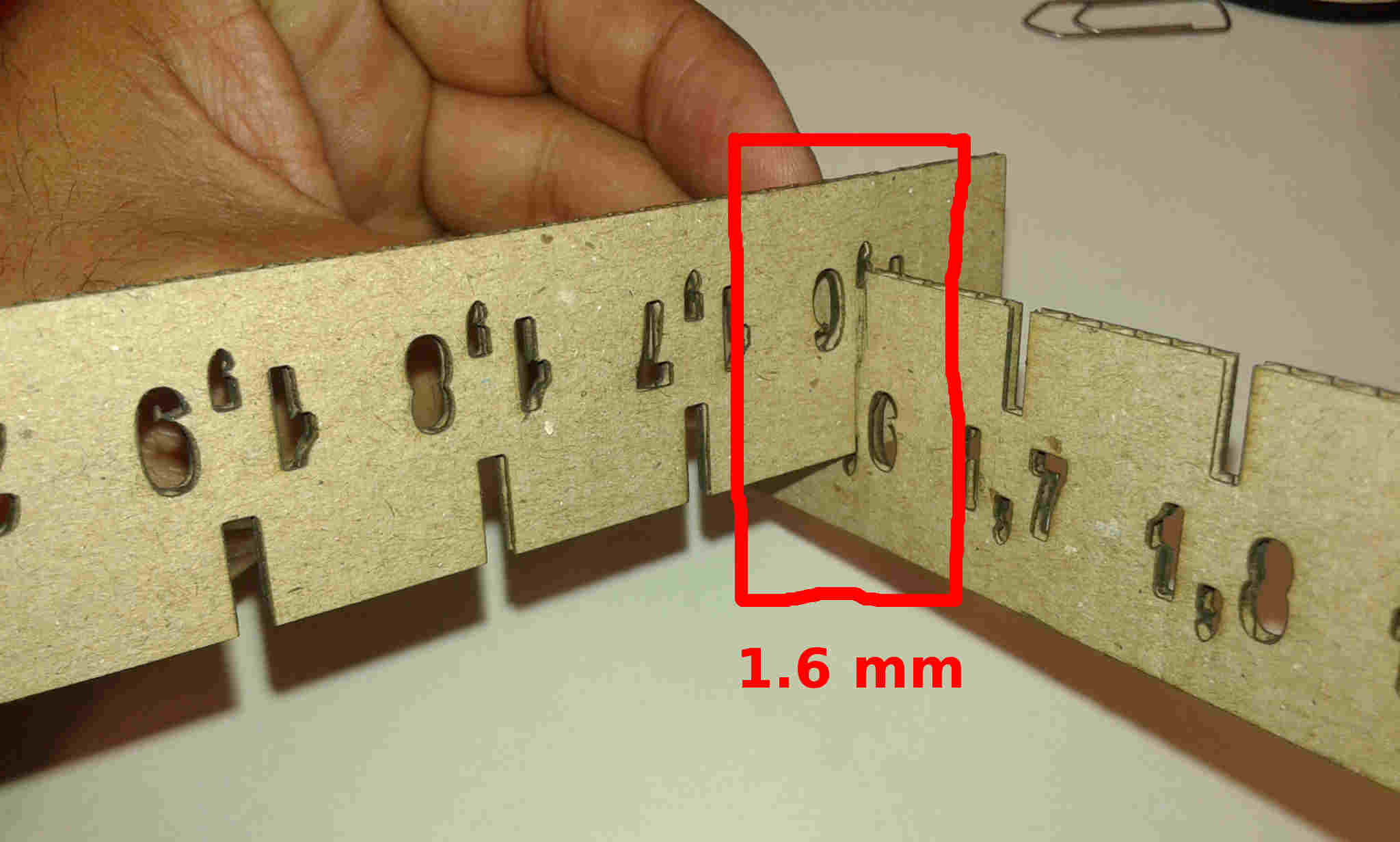
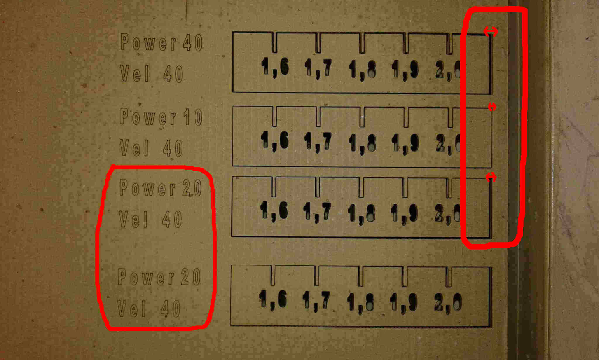
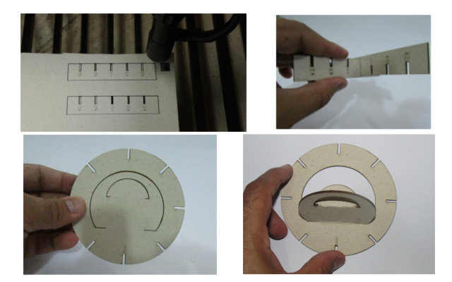
Testing the kerf
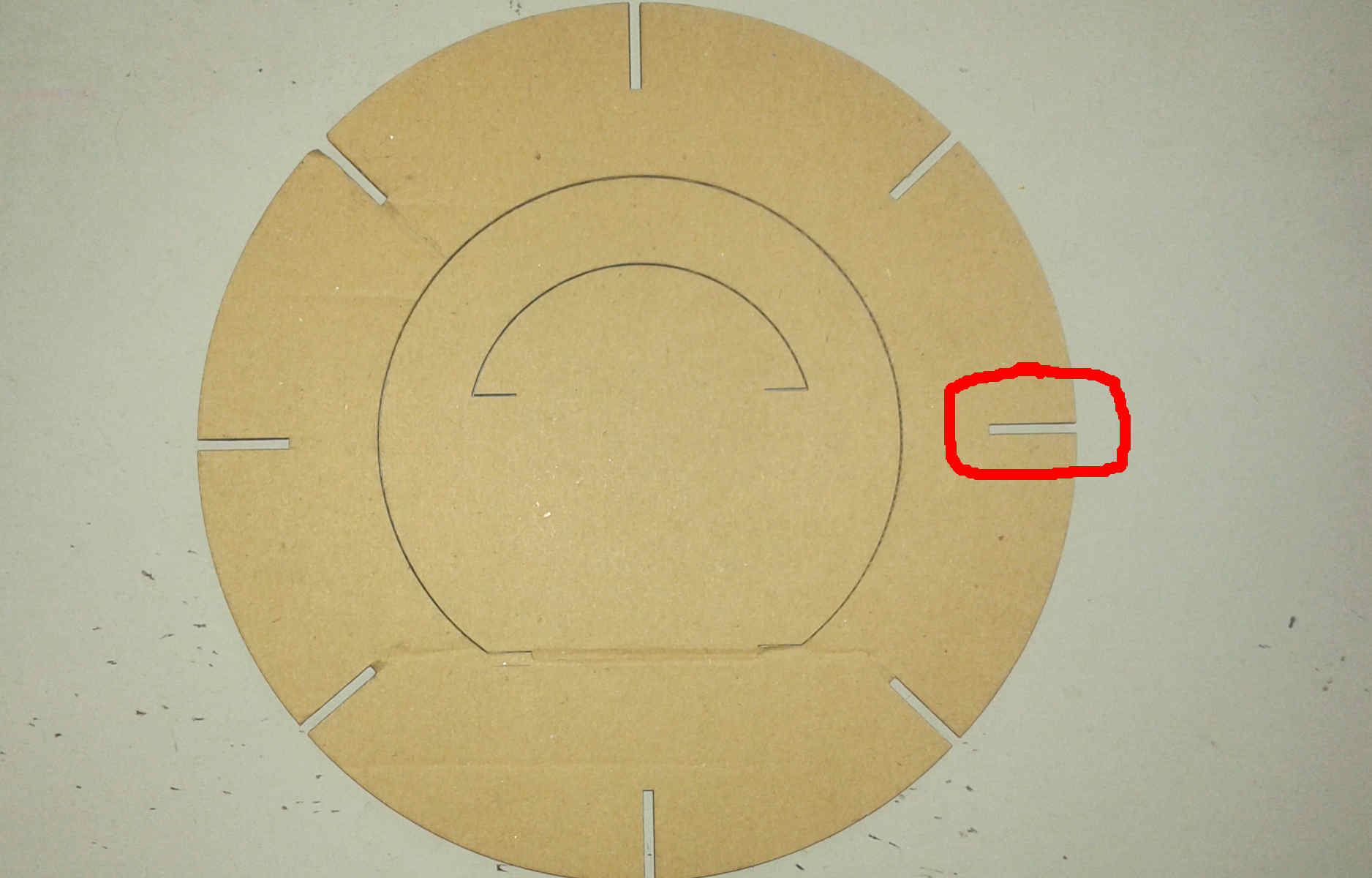
Even though the correct kerf was 1,6 the size of the slot was to small giving instability when applied to the final shape.
Slot too small, I needed to change the parameters
- Changing the parameters with Freecad to fit the join
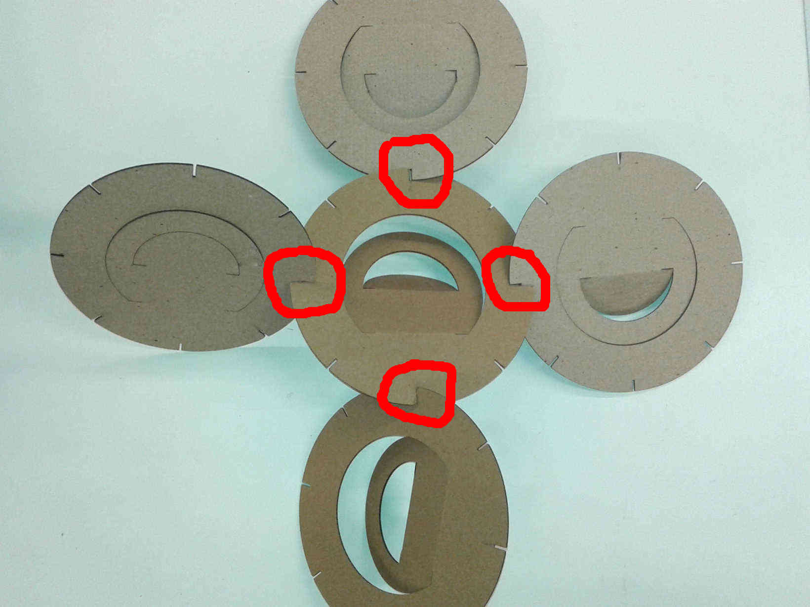
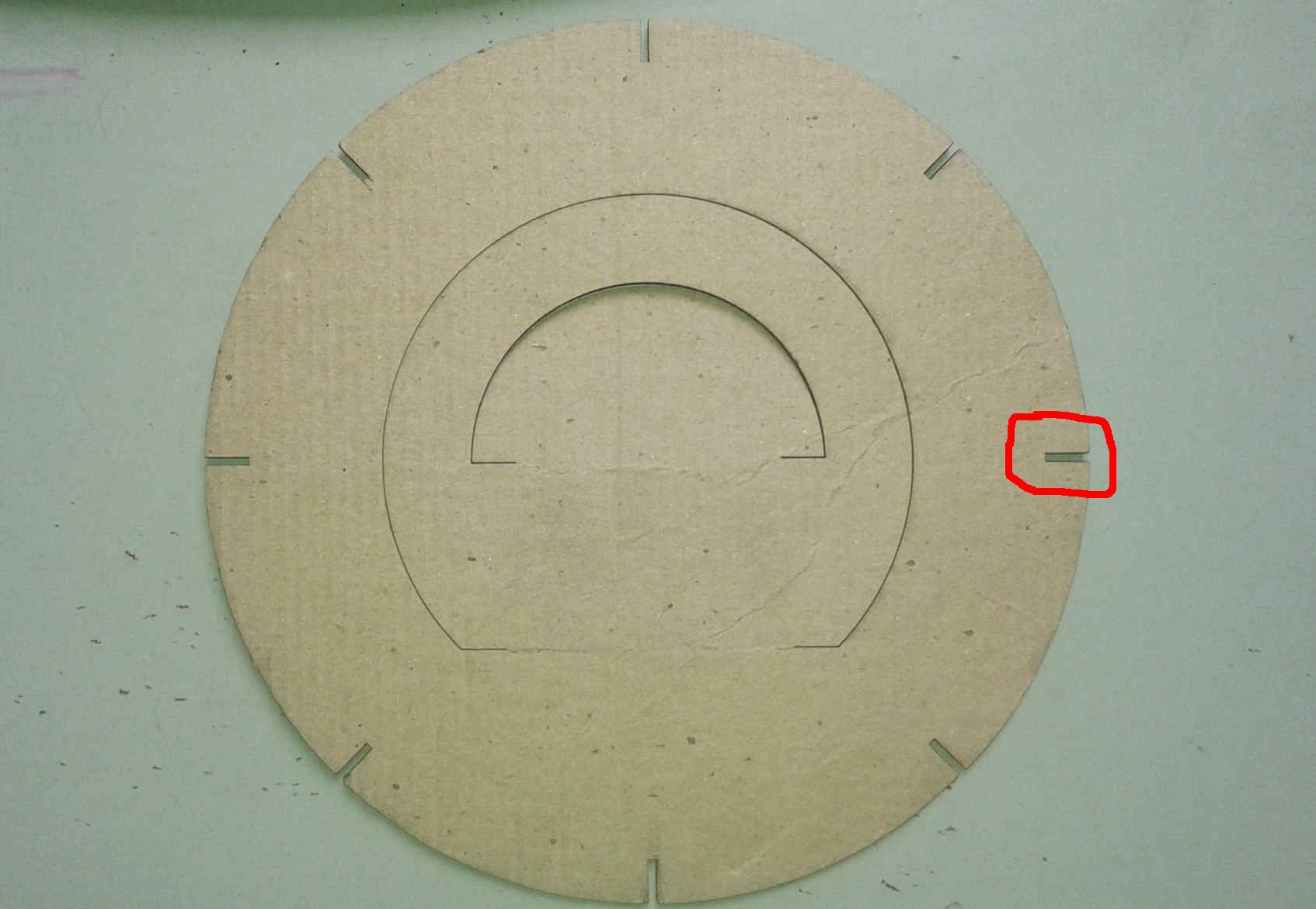
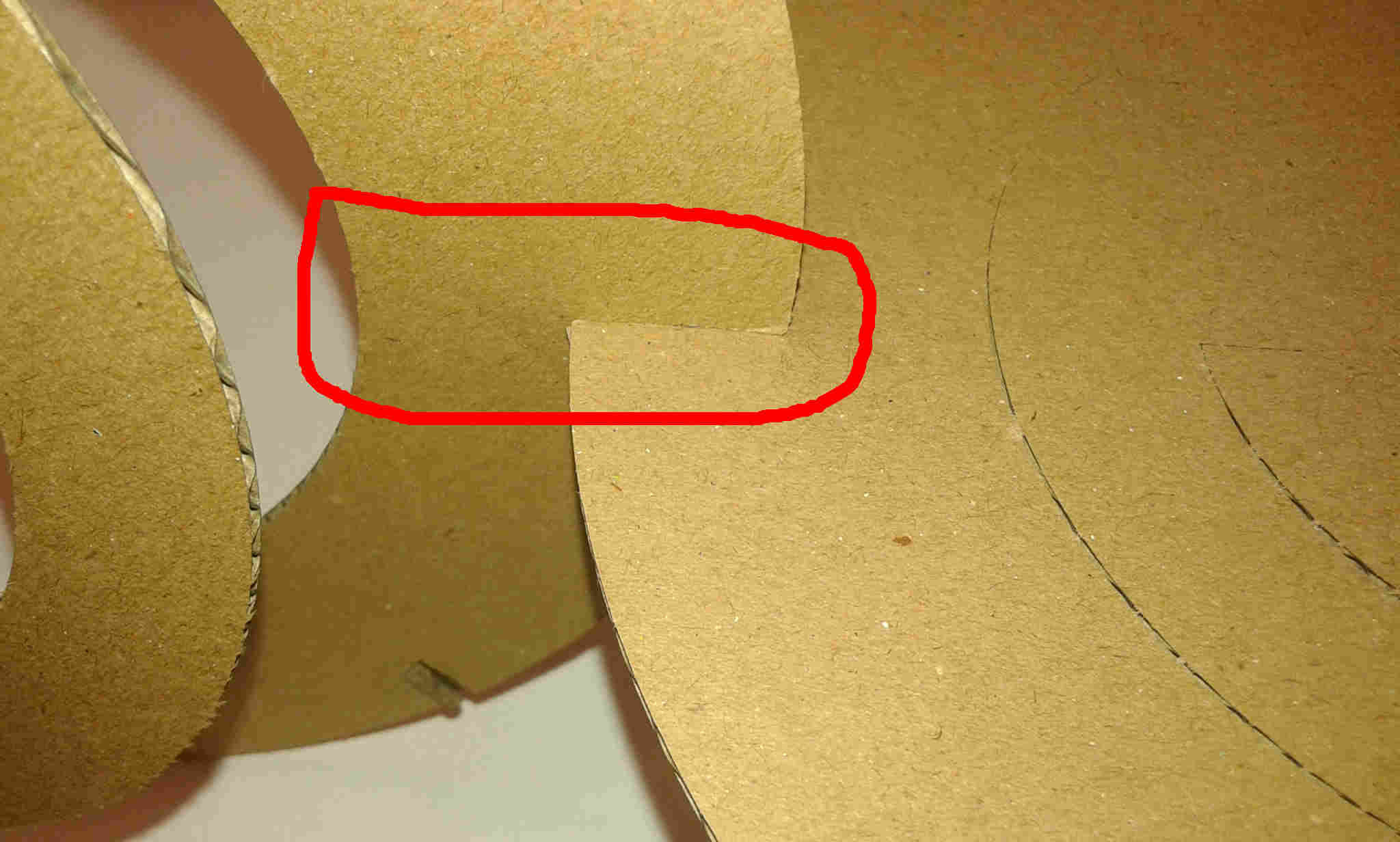
I adjusted the fitting dimension to 20mm parametrically. Sometimes FreeCad easily lost it’s configuration, in order to avoid it I updated the parameter ´s link and I cut it again.
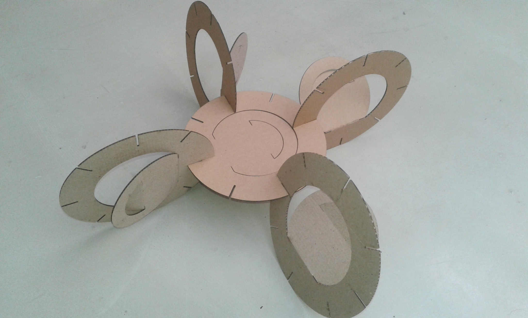
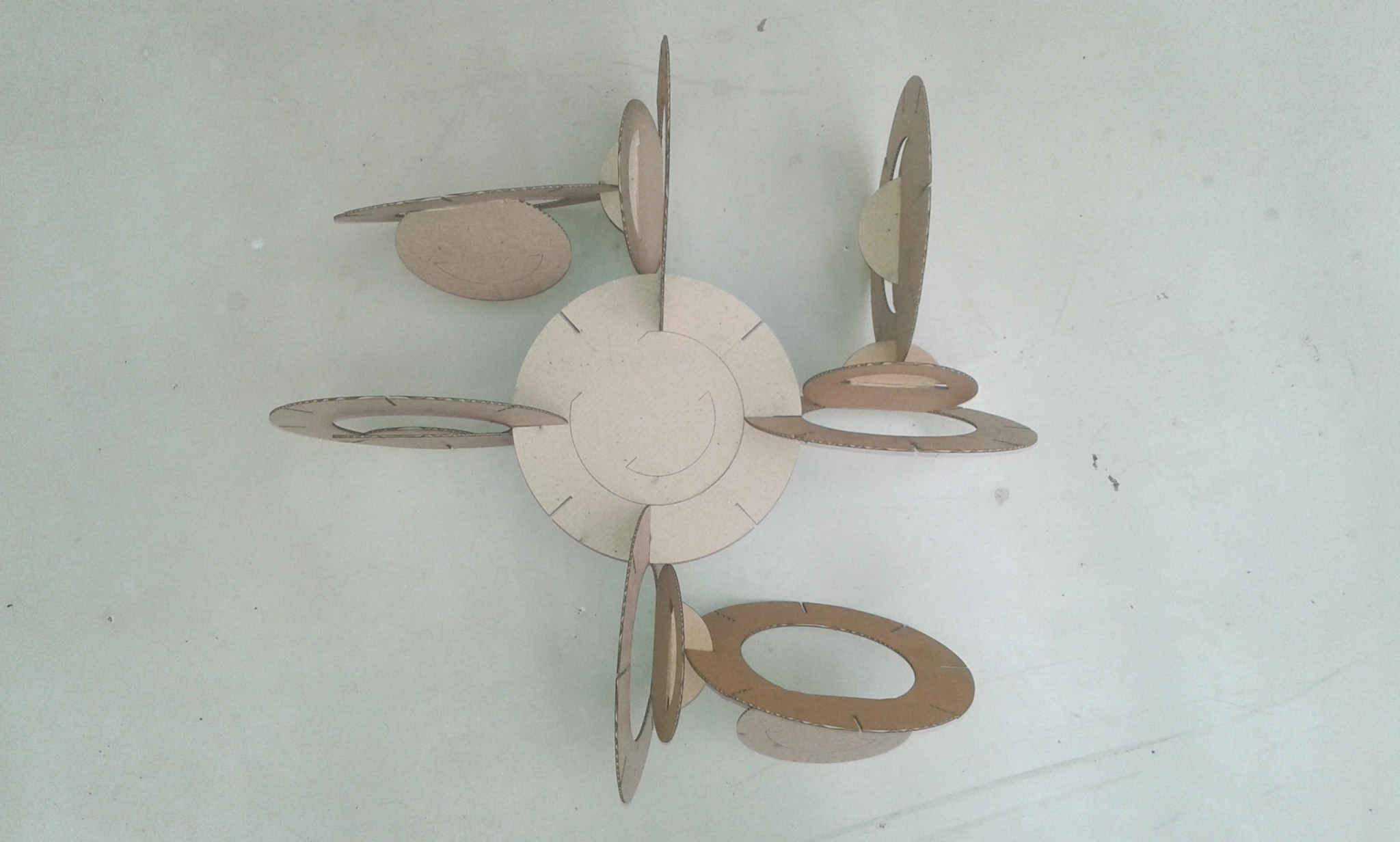
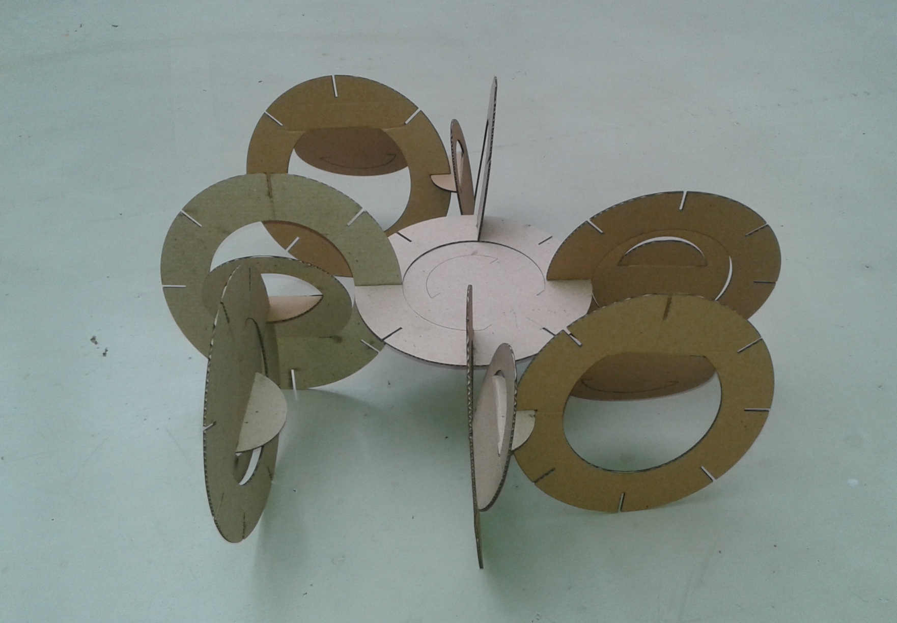
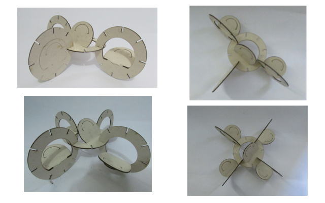
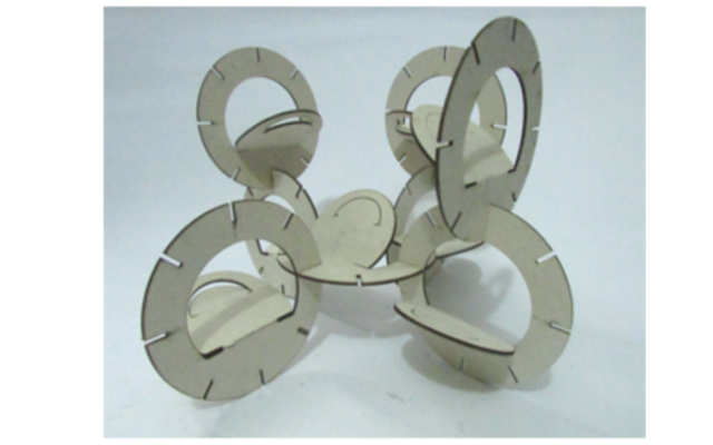
The shape fit to each other nicely. It is possible to do several connections as an object system.
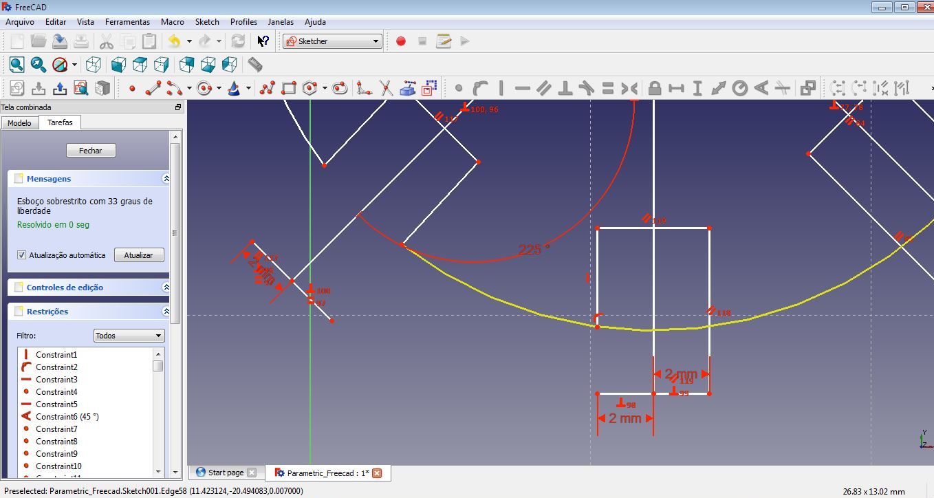
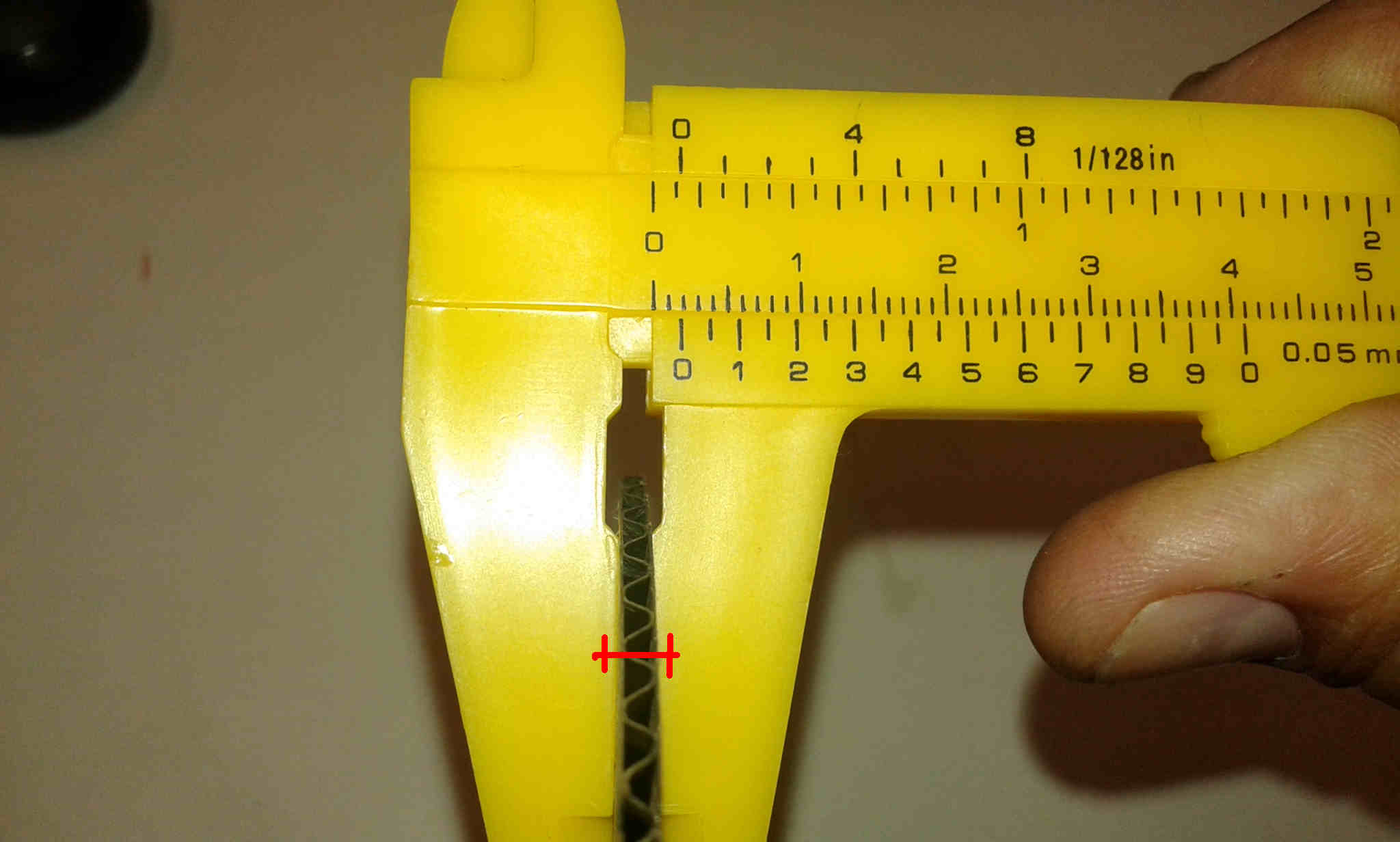
I repeated the same cut using another material (also paper) being it in a smaller scale than the previous. I measured the thickness of the material and did the kerf experiment to test its thickness. The paper had 2mm (thickness) so I did the slots with: 1,8mm; 1,9mm; 2,0mm; 2,1mm; 2,2mm. After testing it I noticed that 1,9mm was the best fit, so I changed the shape parameters through the Freecad in order to export the file for production.
- Conclusions
It is very important to test the machines in order not to waste energy and materials. FreeCAD is a interesting Cad tool, but as any other software, It needs to practice to have a workflow with it. It was much easier to change the parameters of the fittings when working with parameters instead of changing each of the slots one by one (after the kerf test).