CameraSlider
Who's done what beforehand?
Adafruit's bluetooth motorized camera sliderGreatscott's motorized camera slider
Arduslide: Arduino Camera Slider
How much will it cost?
about 1000LE which currently equals about 50USD
What parts and systems will be made?
What processes will be used?
What tasks need to be completed?
None, i finnished all the tasks. Maybe it need further development.
What questions need to be answered?
What is the schedule?
I already finished the hardware part and i have to work moreon the software part till the end of the academy.
Wow will it be evaluated?
It will be evaluated upon the variety of the used modules from the Fab Academy, it's manufacturability, being easy to assemble and its functionality.
Where possible, you should make rather than buy the parts of your project
All the parts except the bluetooth module.
Bill of Materials
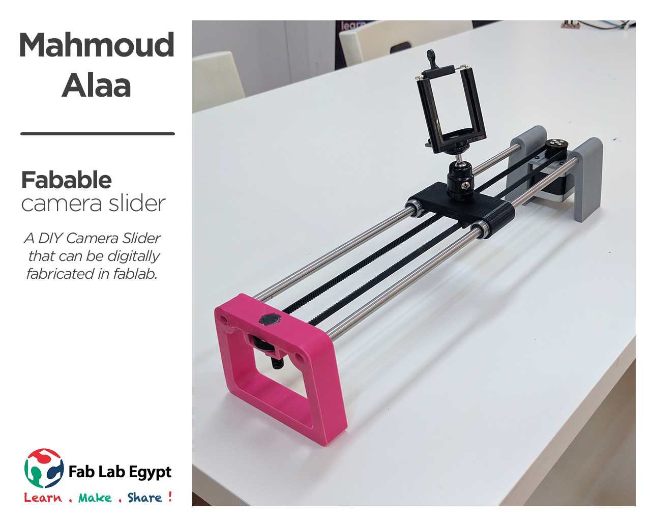
My final project is a smart CameraSlider controlled over bluetooth mobile app or wired remote. i designed the camera slider parts in fusion360 then i 3d printed all the parts and assembled all the parts together.
The Designing process
3D Designing
At first i used Fusion360 to draw 3D design parts of my final project.
I made main part that will contain my pcb and my stepper motor.
then i made the carriage part which will carry the camera and the end of the camera slider which will have the belt idler.
2D designing
the last part is the timing pulley for the stepper motor. i wanted to laser cut it from acrylic for higher quality than the 3d printing. so drew 36 tooth pulley and made 3 layers of it and 2 extra layers for holding the belt in between all connected together with 4 M3 Screws.
.png)
.png)
Then i laser cut the parts with acrylic.
.jpg)
.jpg)
.jpg)
.jpg)
Output Devices
Designing
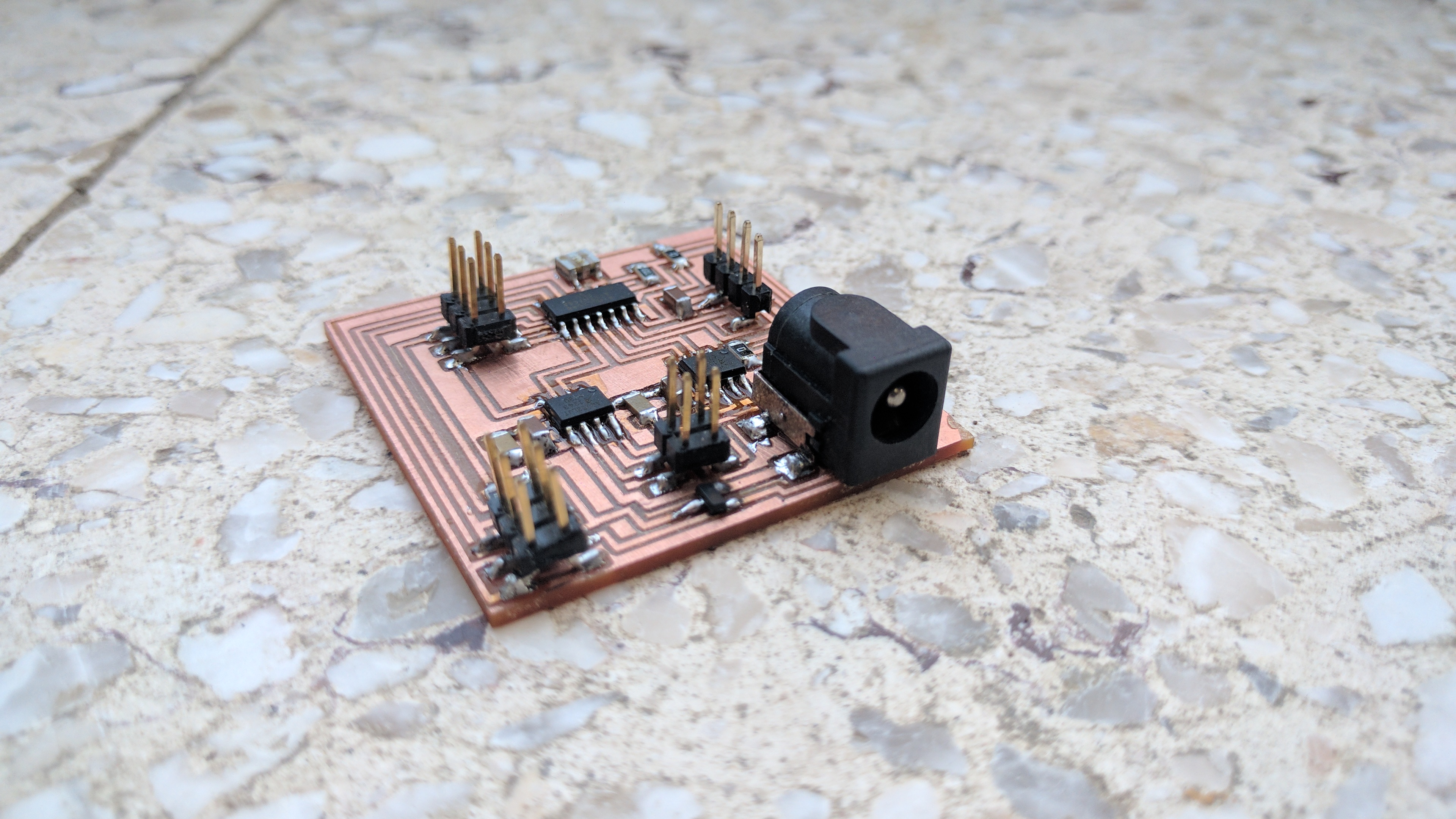
Because my final project is a motorized camera slider so i will use stepper motor so i need to make a stepper driver so i copied niel's design and code to help me fabricating my board. I added power jack and 2 extra input pins because i wanted to add buttons to control my motor later on.
.png)
.png)
.jpg)
.jpg)
.jpg)
After soldering the board i found out that i havent connected the LSS Pin of the h-bridge chip to the ground so i shorted it with jumper wires and soldered 2 smd leds to the motor pinouts to check the signal.
.jpg)
After finishing the board i tested it with niel's code.
After i tested it i fixed the connection problem and changed the ftdi header to 4 pin headers (VCC,GND,TX,RX) because i am going to use a bluetooth module in my final project to control the camera slider.
.png)
.png)
.jpg)
.jpg)
.jpg)
.jpg)
After finishing the board i tested it and it worked perfectly.
Hero Shot
Networking and communications
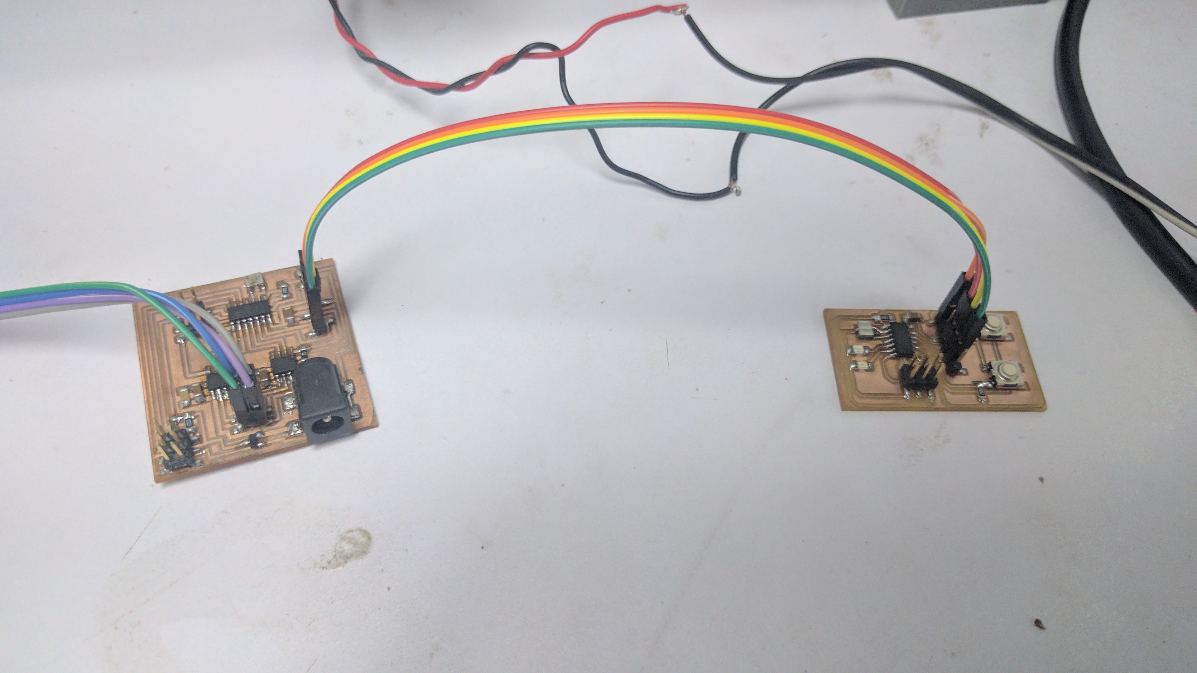
I will use the input circuit that i have made earlier with the 2 buttons and the led with the output circuit which is the stepper motor circuit and make the stepper move backwards and forwards with it.
Programing
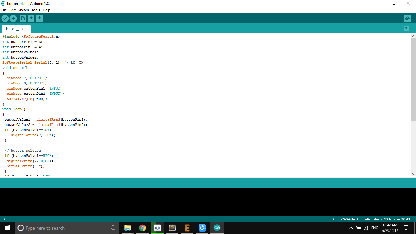
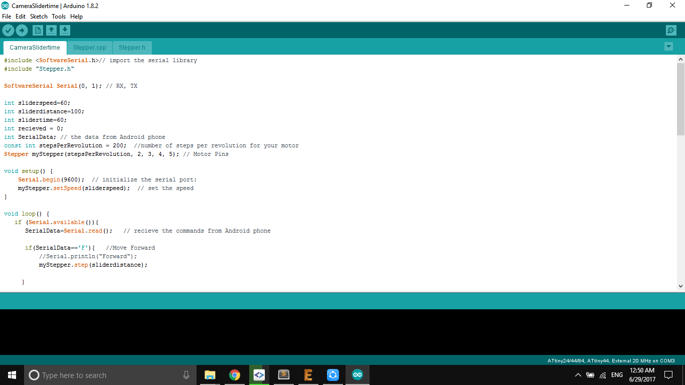
I started programing the input board to send two char for each button, one will send "F" to move forward and the other will send "B" to move backwards. and the other board "the stepper circuit" is programed to move according to the char thats is getting from the serial.
Testing
I connected the GND and VCC and Swapped the RX and Tx and started pressing the two buttons.
Hooking up the Everything
After finishing up every thing the 3d printed frame and the laser cut belt pulley i started assembling everything together the i started hookigng up the electonics. i connected the bluetooth module to the main board and connectred the stepper wires then mounted everything in the frame.
Interface and Application Programming
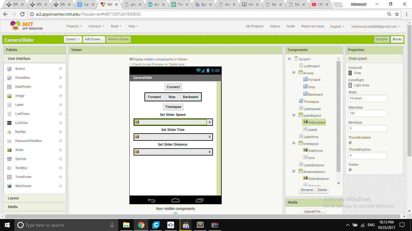
i had to make or write an application that interfaces with an input and/or output device that i made. my final project is a smart camera slider controlled over bluetooth with android app. so i started to make an android application to control the camera slider. i found that amazing website called mit app inventor its an educational tool provided by mit that helps you buid android apps with drag and drop scratch style coding. i googled for tutorials and i found this youtube tutorial that teaches you how to build an android app that interacts with arduino over bluetooth.
The User Interface
in my app i need to control the direction of movement, speed, time, distance. so i added 3 buttons for movement (forward,stop,backward) and another one for connecting to the bluetooth, 3 sliders(speed,time,distance) then i changed the parameters of every single element like the text, colors and the postion.
The blocks
in order to write the code i had to drag and drop blocks of code and snap them together so they can make sense. i followed the youtube tutorial instructions to build my app.
the first two group of blocks are in control of the bluetooth and how to connect and pair.
the left side group is in charge of the sliders for example "when sliderspeed postion changed do the following: send the char V and the slider postion over the bluetooth and set speed text to slider postion".
the right side is in charge of the buttons. for example "when button forward clicked do the following: send the char F over the bluetooth".
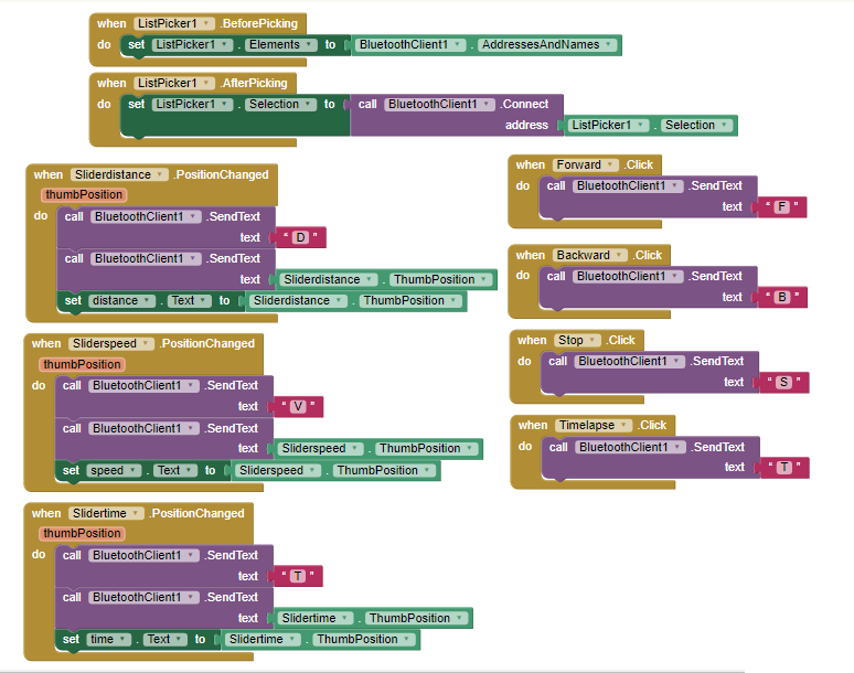
after finnishing my app i saved it on my mobile phone. and it worked like charm!.