Networking and communications
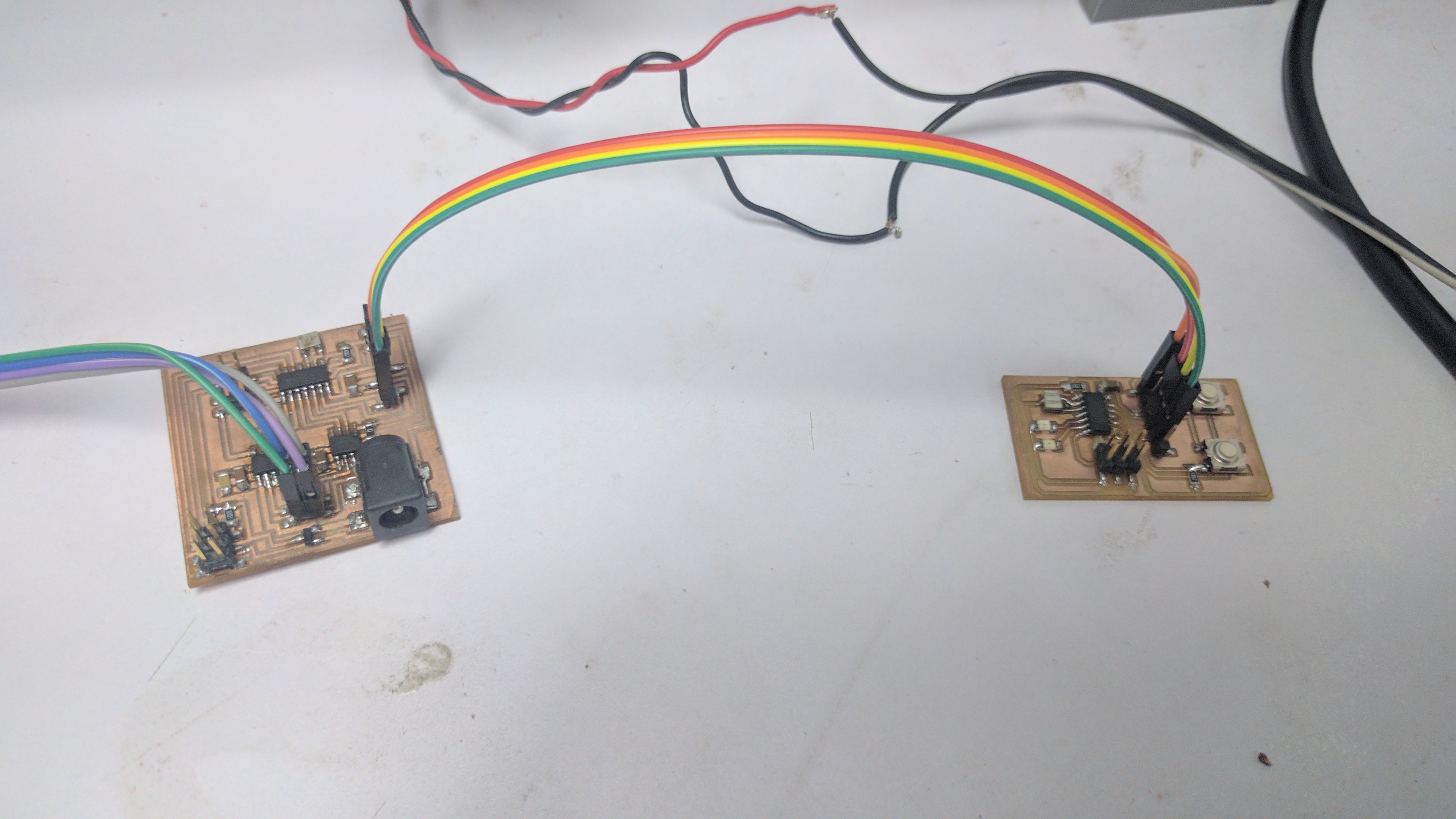
This week we were told to Design and build a wired or wireless network connecting at least two processors. So i will use the input circuit that i have made earlier with the 2 buttons and the led with the output circuit which is the stepper motor circuit and make the stepper move backwards and forwards with it.
What Networking protocol i am going to use?
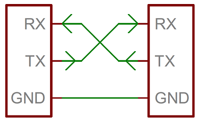
I am going to use normal Serial Communication with tx and rx pins to make the input board communicate with the stepper driver board. A serial bus consists of just two wires one for sending data (TX) and another for receiving (RX). Any serial devices have two serial pins the receiver (RX) and the transmitter(TX). Those RX and TX labels are with respect to the device itself. So the RX from one device should go to the TX of the other, and vice-versa like the figure shown down below.
So if i want to make more than microcontrollers to communicate i can connect them all with serial pins like i showed before and name each one so i can address it correctly. for example if i wanted to use more than one microcontroller i will give each board a number and when i call than number in the serial channel that board with that number is going to respond with char. this addressed board (1) have the following code (if recieved number == 1; then Serial.write="ok";) in this way we can add unlimited number of microcontrollers to communicate together.
in my case this protocol wasn't implemented and i wasnt able to implement it due to lack of time. but i will try to implement it in the future.
Programing
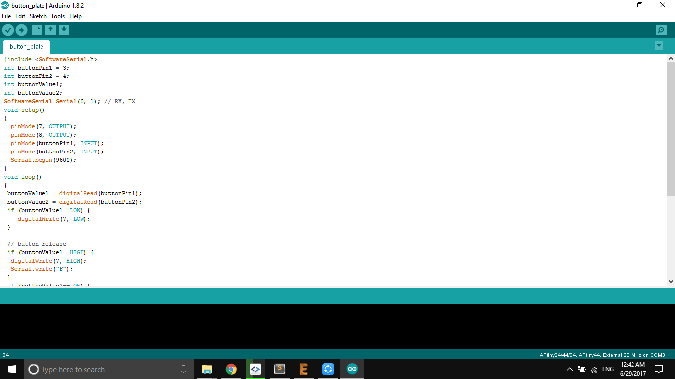
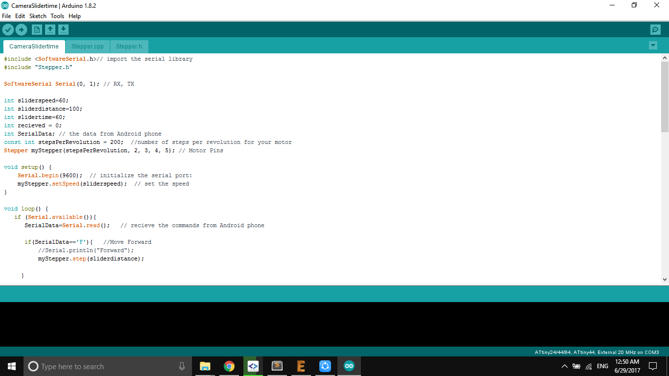
I started programing the input board to send two char for each button, one will send "F" to move forward and the other will send "B" to move backwards. and the other board "the stepper circuit" is programed to move according to the char thats is getting from the serial.
Testing
I connected the GND and VCC and Swapped the RX and Tx and started pressing the two buttons.