Embedded_Programming
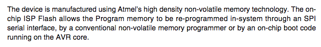
The main character in embedded programming is the microprocessor one is going to use. You should know it´s pins and how they are reserved, to be able to write your program according to their applications. If you want to deliver a package to Mr. X you should know at which room number you have to knock. I`ve used ATtiny 44 and my board design is based on the fabacadamy's 6. electronics design declarations two weeks ago. I've added a 16MHzresonator, one LED and a button to my board. Now, I have to program my board via my programmer I have produced in the 4th week.ATtiny44 Datasheet

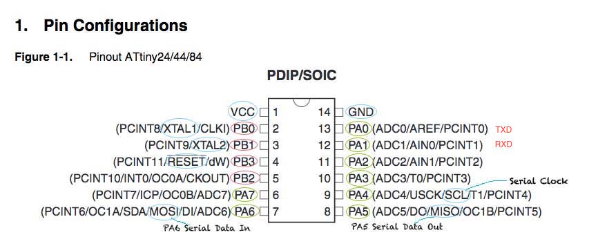
Pin configuration
Explanations:
- The numbers behind the letters are channels E.g. ADC0 or ADC3.
- ADC0-ADC7: Analog Digital Converter
- AREF: External Analog Reference for ADC. In this case pull-up and output driver are disabled
- PCINT0-11: Pin Change Interrupt source 0-11
- AIN0: Analog Comparator Positive Input. Configure port pin as input.
- AIN1: Analog Comparator Negative Input.
- T0,T1: Timer/Counter source 0, 1
- USCK: Three-wire mode Universal Serial Interface Clock
- SCL: Two-wire mode Serial Clock for USI Two-wire mode.
- DO: Data Output
- SDA: Two-wire mode Serial Interface Data.
- DI: Data Input as USI Three-wire node does not override normal port functions pin has to be configured as input for DI functions.
- Miso: Master Data Input, Slave Data Output for SPI channel
- Mosi: Mater Data Output, Slave Data Input for SPI channel
- OC1B: Output Compare Match output. Can serve as external output for Timer Counter1 MatchB. OC1B pin is also a output pin for PWM moder timer function.
- OC0B: Output Compare Match output. Can serve as external output for Timer Counter0 Match B. Output pin for PWM mode timer function.
- OC1A: Output pin for PWM mode. Timer/Counter 1.
- OC0A: Output pin for PWM mode. Timer/Counter 0. Can serve as external output but has to be configured as output (DDB2=1)
- CKOUT: SystemClock Output, when CKOUT Fuse is programmed.
- CLK1: Clock Input from external clock.
- XTAL1, XTAL2: Chip Clock Oszillator pin1, pin2 used for chip clocks. When used as clock it can not be uses as I/O pin. When internal Oszillator is used, then pin serves as ordinary I/O pin.
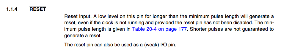
- Reset: Ecternal Reset INput is active low and enabled by unprogramming "1" the RSTDISBL Fuse. When pn is used as Reset pin output driver an digital input are deactivated.
- dW: When debugWire Enable (DWEN) Fuse is programmed and Lock bits unprogrammed. It is configured as a wire and bi-directional I/O pin, that means it is a communication gateway between target and emulator.
Vcc pin is marked with a ring in the corner.

The Debug wiring on pin PB3.
How to Reset.
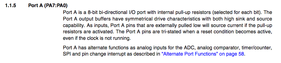
General informations about PortA:
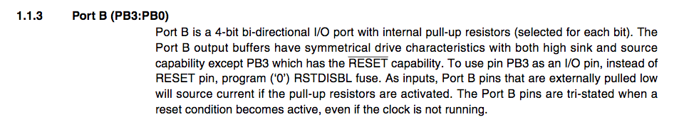
General informations about PortB:
What happens to unconnected pins?

Some informations about internal 8MHz clock:

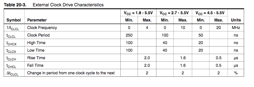
How can I use an external clock on PB0?

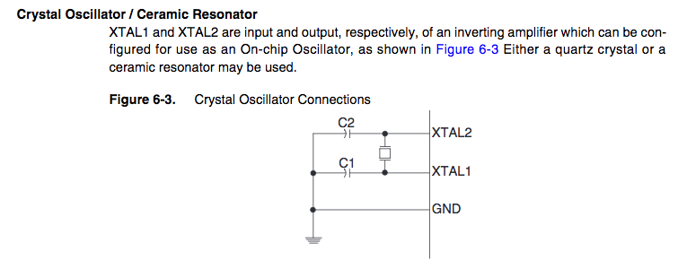
A crystal needs two capacitors.See below how they are connected and which capacitors are recommendet for frequency range (MHz). A resonators architecture is the same just build-in. Use an external Resonator or crystal between Port PB0 and PB1:
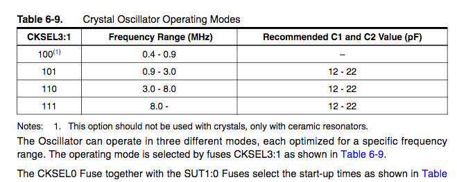
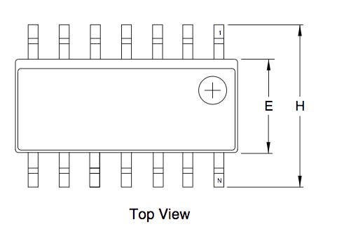
Finally, the operating modes, like temperature and voltage:


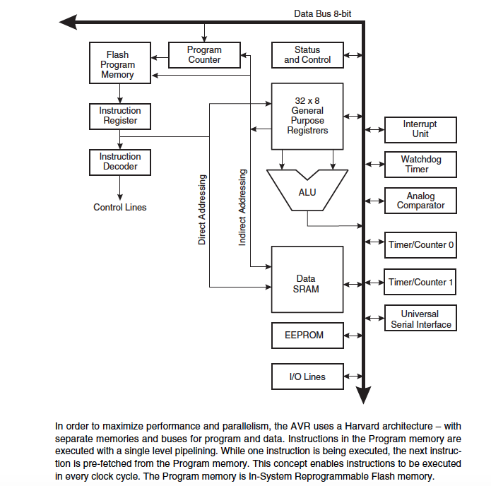
The Architecture of a ATtiny44
The AVR architectur of ATtiny44 is based on Harvard architecture. CPU (Central Processing Unit) is the core of a processor. CPU has two duties: 1. execute instructions and 2. regulate processes within the system. We can split the CPU up into A Instruction Processor and B Data Processor. The Data Processor is responsible for calculations and data processing. Main feature of it is ALU (Arithmetic Logical Unit) for all calculations. Register is an other important feature for saving all results in a storage. It has an Akkumulator which is devided into MR (Multiplier),L (Linkregister for adding and MBR (Memory Buffer Register) serving for communication between Register and Instruction Processor.The Instruction Processor ist devided in two sectors: 1. Instructions Decoder and Register. Register itself is split into IR (Instrucion Register) for current instructions; MAR (Memory Address Register), where to find this instruction; and PC (Program Counter) which knows the address of the upcoming instruction.
Process
One can split the process in two stages: 1. Fetch Stage, 2.Execution Stage- 1. Fetch stage
- The next request is a content of PC and is uploading into MAR.
- MAR knows the address of the instruction, fetchs it from the storage and sends it via MBR to IR.
- 2. Execution Stage
- The instruction is decoded by the Instruction Decoder and
- is sent to ALU for arithmetic operation.
- The result is sent to be stored in Akkumulator
- Finally, PC (Program Counter) gets a feedback that the instruction is executed

It is characteristical that a processor is executing one instruction for one data value: (SISD- Single Instruction, Single Data). A processor is always working with data, instructions and addresses. Data and programs are stored in a storage and are accessible from outside.
In the datasheet for ATtiny you will find a drawing with thick lines called Data Bus 8-bit. It is bi-directional. A data bus consists of several parallel wires transporting different values. The thicknes of a bus is defined by the number of wires.
USB (universal serial bus) is a serial connection one line only. A processor is working with a parallel connection. By this several informations can be transported at once in both direction. The number of wires defines how many memory units can be addressed. The datasheet says 8-bit, that means 2^8 = (in total 256 Bit) memory units can be addressed at the same time. In addition 32 general purpose working registers are directly connected to ALU.
Programming Attiny44
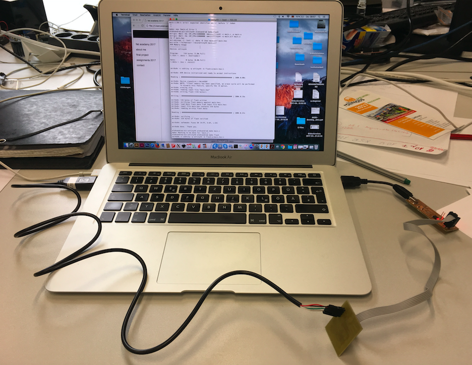
Main feature for me is, how to get out of my computer into my selfmade board. I really tried to understand it, because it was a bit like roulette: one time it worked out and next time it didn´t work out. I try to repeat what I have learned: To programm the new board first I have to make it programmable, set devices, fuses, clock and so on. I downloaded the Makefile from fabacademy's homepage, changed the name into 'Makefile' and created a new folder for Makefile and C-program. Both have to be in the same folder. I adapted the makefile fo my needs, like the clock: from 20MHz to 16 and compared the fuse addresses. For the fuse address I can look up in Internet: Engbedded is a homepage for calculating fuse address.Then I downloaded 'hello_world_c' from fabacademy' homepage, modified it, too, and put it in the same folder. I opend Terminal, changed to my folder and run 'make' See below the report:

This 'make'advice created o-, hex- and elf- files. See below how I connected my board and my programmer to my computer:
Problems with programming
But I got quiete some problems with programming LED and button on my hello board. Sometimes it worked out sometimes my computer couldn´t find usb device. I´ve checked all connections again and again. I did some logic analysings and found out that may be my soldered resonator is not working exactly. But Tobias our instructor said if you measure the resonator the measuring instrument can cause distractions. Later on I´ve realised together with Daniele , our Guru from Kamp-Lintfort that 1. my programmer has only one opened jumper and not two. That means my programmer gets power through my Hello_board, and 2. my TTL Kabel is a replica and my Mac has problems to find its device or get confused with the address. I odered a new one.Blinking LED
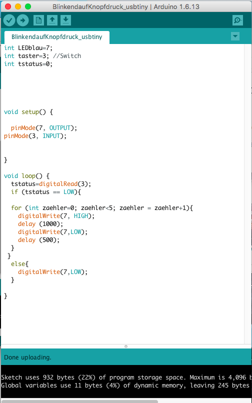
I took the blinking LED C-programm from Marcel and made some changes: instead of writing ten times: 'LED on' and 'LED off' I programmed an if-clause with a counter. Then I created a new folder. I copied a Makefile into this folder and run 'make' on Terminal. Afterwards, I connected my boards to my computer and wrote 'make flash'. Now, the blinking programm was flashed on the hello-board. See below: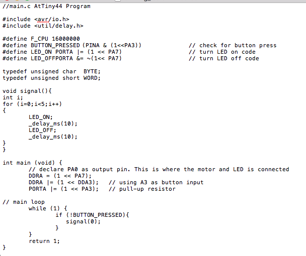
LED blinking text for downloading:
blinking_led
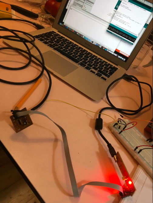
As I´ve got so much trouble with my device connections and my knowledge about programming and electronics is still small, I decided to start each project very low and easy with Arduino. I wrote a sketch with the help of examples in Arduino and testet it with an Arduino Uno and a breadboard, too, as seen below:

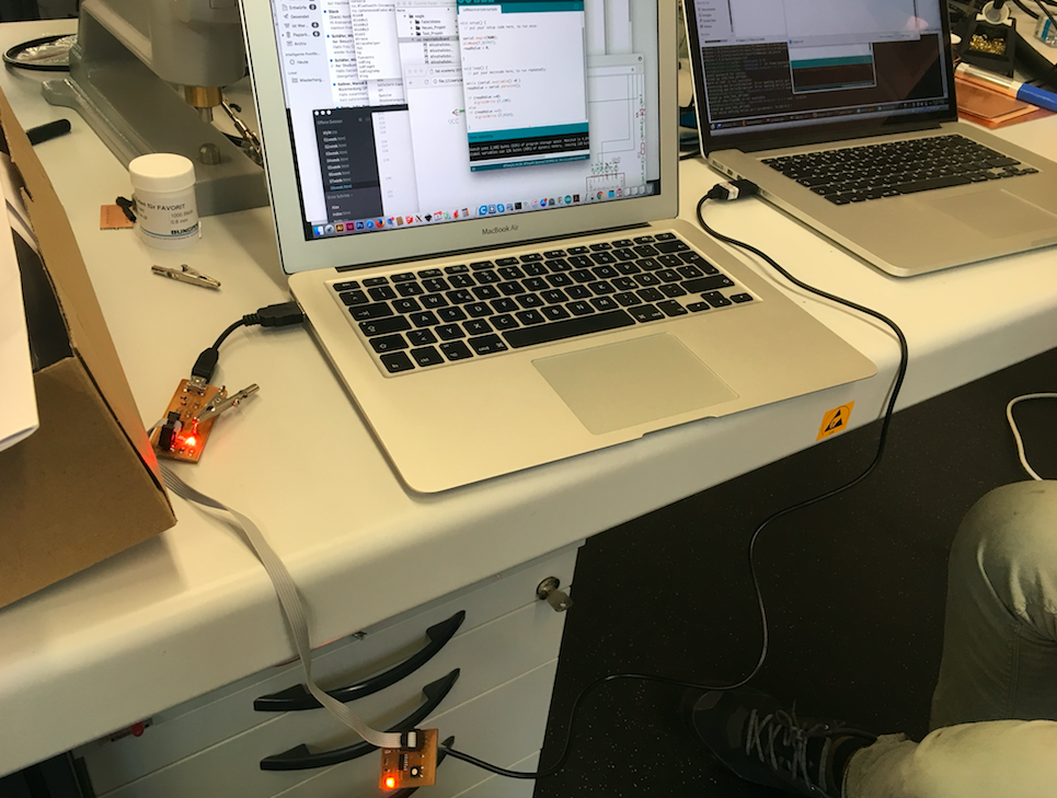
Then I connected my programmer to my computer, I did not connect my Hello_Board to my computer because of the above mentioned problems. See below:

The aim was to press a button on my hello_board and the led on my hello_board is blinking in pre-defined speed and amount. Arduino Program for my Hello_board:
Hello_botton
For this I need my original FTDI cable, I´m still waiting for. In between I developed the program for the arduino board, as seen below, this worked out: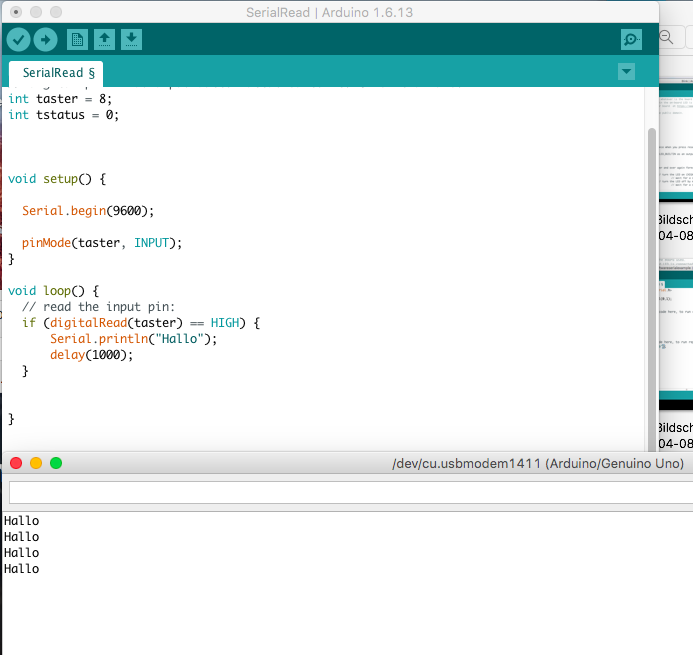
Then I wrote a sketch for my hello_board, included the SoftwareSerial package, see below:
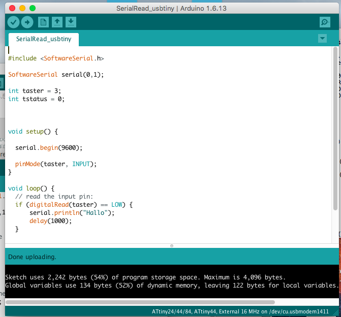
As I still couldn´t test it on my Mac, I tested it together with Danieles Linux operation system:
To fill up my hello_echo feature T´ve tried the same setting, with an original ftdi cabel and adapted hello-echo-44 c program.. The cheap one I´ve bought before is not suitable for Mac as written in its Datasheets. I took the Makefile for my Atmega328p and adapted it to Attiny44. Then I took the hello_echo_file from the fabacademy's tutorial page and included stdio libary. I programmed my hello board with my programmer and then I opened Arduino´s Monitor. I copied the plain c-file in an Arduino window, after adapted all settings in Tool (Board: Attiny 44; Prozessor: Attiny44; Port device: usb-serial-ALO24B6; Programmer as usual: usbtiny. I compiled it and then uploaded the echo file. After opening Serial Monitor I printed the letters. As you can see below, there was a mismatch first with the baudrate:
I set the monitor on 9600 Baudrate, this didn´t work out. Then I switched to 115200 baud.

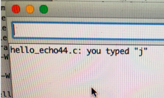
I set the lfuse as recommended on 0x5E and changed the baudrate as above and it worked out.

Enclosed are two files, a Makefile for Attiny44 and hello_ech44.c, as I mentioned before, adapted from FabAcademy's tutorials.
Makefile for Attiny44
hello_echo44.c. You can test it directly on a serial port terminal application like Coolterm for Mac or copy it to Arduino. In Arduino you have to include <stdio.h> library.