„Computer_Controlled_Cutting“
Procedure of Lasercutting is allways the same:Create a file - preferably parametric like eps., dxf. or svg.. . Mark the elements you want to cut, engrave or ignore with colours. It is the easiest way to determine cutting settings later on in Visit. Then, send files to Visicut. Visicut is an open source program developed by RWTH Aachen. If you want to create a file in Inkscape it is recommended (see Visit manual link VisiCut) to use Visicut extension instead of opening the svg file directly. After installing Visicut select Extras/Install Inkscape extension. Then, restart Inkscape and send your file via Extensions/Lasercut/Open with Visicut.
Lasercut Settings
First of all, we did a team session working through some basic explorations: Diameter of laser-beam kerf of our Zing 50. Please see our group assignment page.ZING is the name of our laser cut mashine and 50 means the power(watt) of the laser-beam. To find out the thickness and other characteristics of the laser-beam I followed three ways:
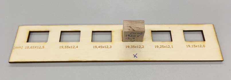
first, through drawing several rectangles with dimensions getting smaller in 0.10mm steps on a 3mm plywoodplate. From clearance fit til fit and press-fit;
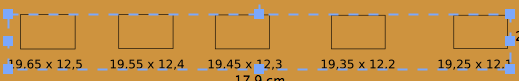
Hier you can see rectangles opend in visicut with below dimensions in green for engraving.

Cutting settings and engraving settings.
You choose the colour you want to cut or engrave in characters. So you choose green for engraving the the dimension below the rectangles
Here, you can see for pressfitting you need to reduce the cutting measures at 0,2 mm.
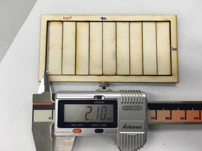
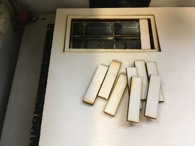
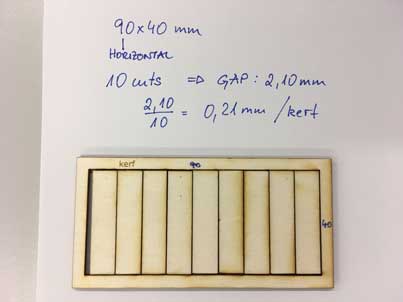
second, through cutting out a rectangle frame with ten inner straight slices, measuring the total gap and dividing it by ten.
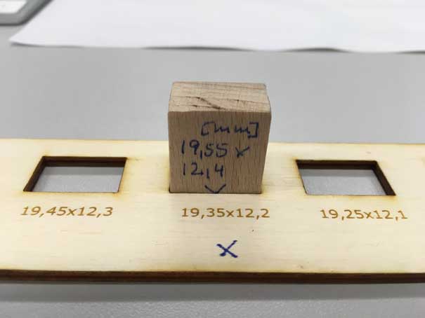
third, through cutting several times into a bigger piece of wood (19.55 hight). By adjusting the focus in view steps we could find out more about the cone-shaped kerf. In Focus settings number 1 implies 1mm below surface.See Focus Settings.
Focus Settings
What happens to the cutting edge, if we vary the focus of the laser-beam? To answer this question we set the focus 0,1,3,5,10 mm beneath the surface of the wood material we wanted to cut. It is definitely interesting to see that 10mm focus cut is wide and very short (only 2mm deep) and the higher the focus the longer the slit.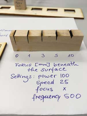
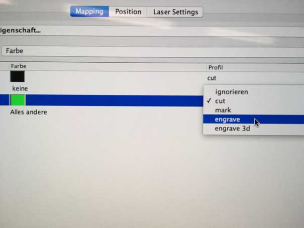
The laser cut settings in VisiCut
Please, find below some VisiCut setting informations. Again, do not open .sag files directly, open them by Inkscape. The extension does some clean up or converts elements like txt into path… Afterwards, set the material you want to cut (multiplex,plywood…) and the thickness (3mm, 4mm,…). In Mappings you can determine which object you want to cut, engrave or just ignore. It is quite easy to determine by colours e.g. green lines = cut; red elements= engrave… . The default laser profiles are: cut = cut through; mark=less power ore more speed; bitmap engrave= „dither“ black or white pixels (dithering algorithm).The raster job will work as follows: black pixels= laser-on; white pixels= laser-off. The lower the resolution the bigger the pixels and less linesLink Visicut
Owe to the focus on problem is bended wood material. You have to take care about it, flatten it somehow or choose plane wood plates.
Zing50 machine settings
Turn on the machine, the main ventilation and if possible compressed air. Position the wood plate by laser pointer. Press Focus on.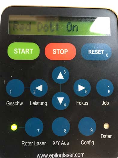
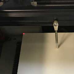
Adjust the hight of the wood plate with pendulum sticking to the laser beam. Press the up-down buttons. Don´t forget to stick it back and turn of the Focus. Choose job you can see it in the message line. Press Start. Keep your laser cutter always clean!
Vinyl Cut Settings
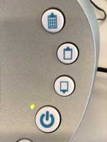
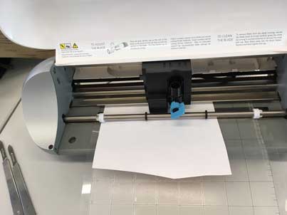
Our Silhouette is small an easy to use. After turning on you just have to press on top button to pull in you foil sticking on a cutting mat. After the job is done you press button right above the on-off switch.
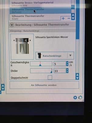
In Silhouette Studio you choose the material you want to cut and the program proposes speed value. After that I started to set the blade.
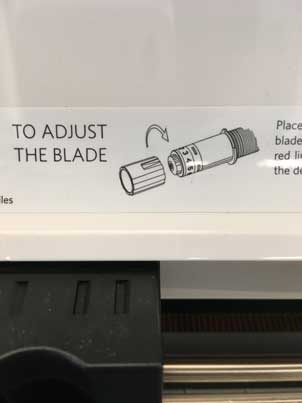
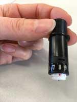
You adjust the blade by turning a small scroller marked with numbers, the blade is coming out the higher the number.
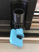
You turn this blue lever to be able to take out the blade in the bladeholder. Don´t forgett to fix it later.
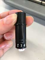
I started adjusting the blade from step 1 but til 3.5 nothing happend.From stepp4 you could see it was welted. Step 7 it started to cut partially and cut through by step 8.
Afterwards I used normal printing paper.
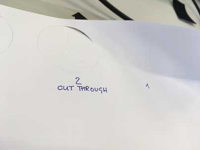
It was cutted through by step 2.
Finally, I wanted to cut quite thick drawing paper-thickness 0,48mm.
It was marked and scored a bit at the higher step numbers, but even step ten didn´t cut through. I´m definitetly sure that our Silhouette doesn´t have enough pressure on the blade.
Vinyl cutting
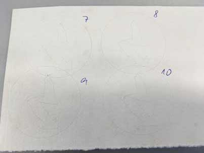
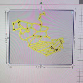
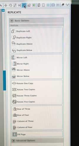
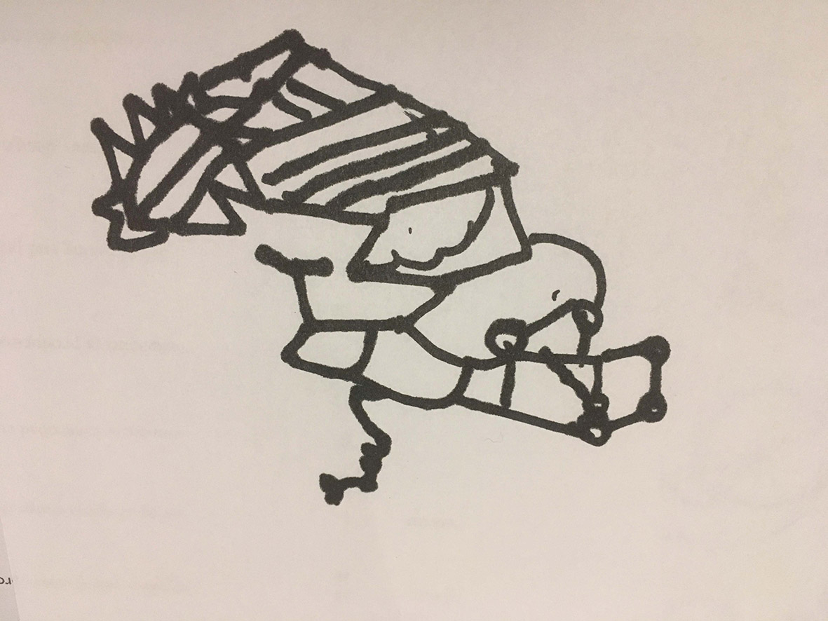
This time I wanted to take a hand drawing für vinyl cutting. I took a picture and scanned it as jpg file (it is also possible to send it by Air Drop nowadays, but somehow it didn´t work out this time). Then, I opened it in Silhouette Studio and made some settings: After some page settings I had to scale the picture. Then I traced it and replicated it. I dragged the original picture away and selected the traced one to be able to mirror it.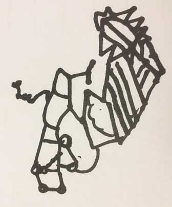
I scanned this handdrawing and opened it in Silhouette Studio.
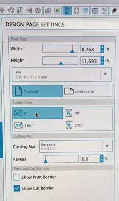
With page settings I can adjust my page dimensions depending on my needs.
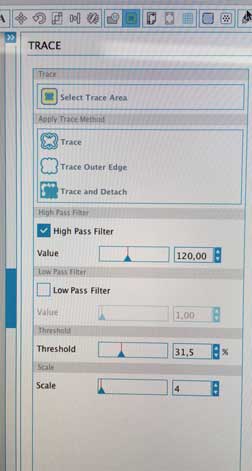
Trace is a tool for selecting the trace area and choosing the way of tracing like trace all Lines or only outer edge...With the Pass Filter I can adjust the way of tracing, too, thinner or wider lines.
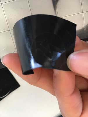
The mirror one I kept, the other one I dragged aside. Afterwards I selected the cut settings and prepared cutting. Before I click the bottom to start I positioned a piece of vinyl foil sticking on a A4 medium between two white rings. The foil needs to be minimum as big as the drawing.
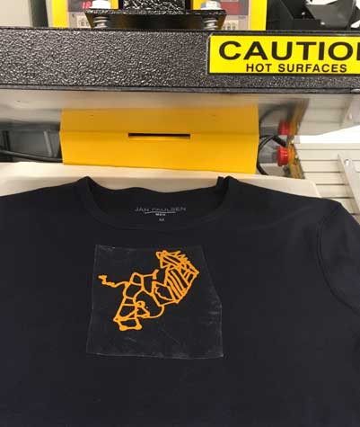
After cutting I had to remove the parts I didn’t need and placed the finished piece on a t-shirt. I put the t-shirt between to hot plates (180 degree) like a mangle. and pressed them together. Fusing is finished after a few minutes. You will hear the loud and ugly noise marking it.
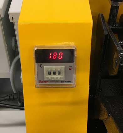
One have to adjust the temperatur appropriate to the qualities of the foil you want to apply.
If you look up in internet you will find a lot of foil-selling shops, just look for "soft-heat-transfer-foil".
Link Silhouette
Download Drawing
Download Handdrawing as svg
Working parametric in Fusion360°
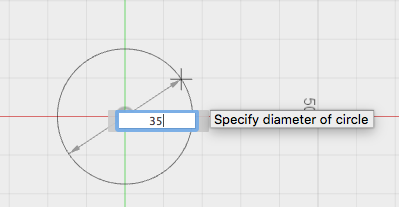
You can already start working parametric in the sketch plane and later on in 3d modelling. The most important characteristic for paramatric working is creating dependences. A distance, angle or any other kind of proportion or relation or constraints (like tangential or vertikal..) between the lines, the bodys and between the drawing and the axis helps creating a parametric object.For example, create a sketch and draw a circle. Then draw two more circle let them intersect.
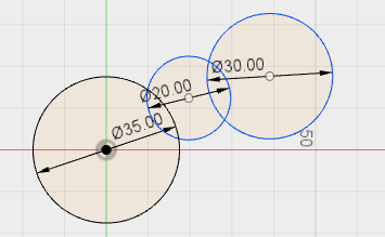
Then choose Tangent tool in the constraint bar and click on two circles. The jump into a tangent position.
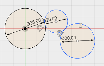
Draw a rectangle somewhere nearby, make the same constraint. Then change the diameter of one. You can observe how all the other circles jump into a new position but allways tangential.
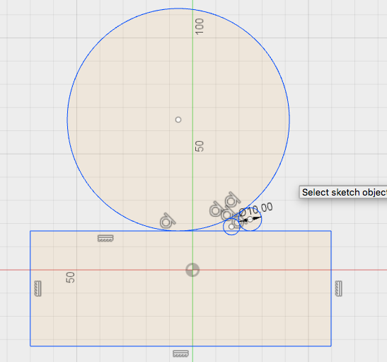
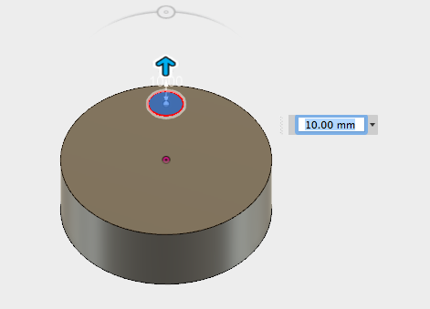
Now, create a new design. Draw a big circle, stop sketch and extrude.Create new sketch again, choose the surface of the cylinder as the plane for your sketch. Draw another circle, 10mm.
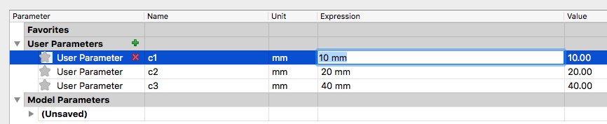
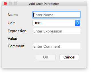
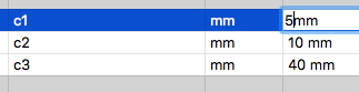
Then go to Modify\Change Parameters in above toolbar and add Parameters e.g c1 = 10mm, c2 = 20, c3 = 40.
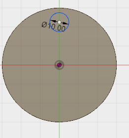
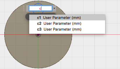
Then go back to your sketch and rename the dimension note of the small circle into c1 (that means 10mm).Stop sketch and choose Extrude. If you were already out of sketch modus you can also go to the timeline at the bottom of the main window and right click on the sketch symbol. Choose 'edit sketch'. Than aktive dimension of the small circle and rename it.
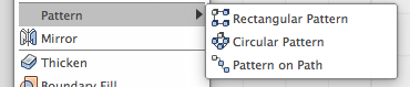
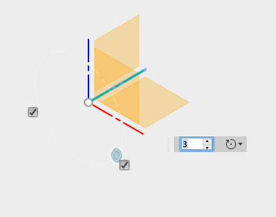
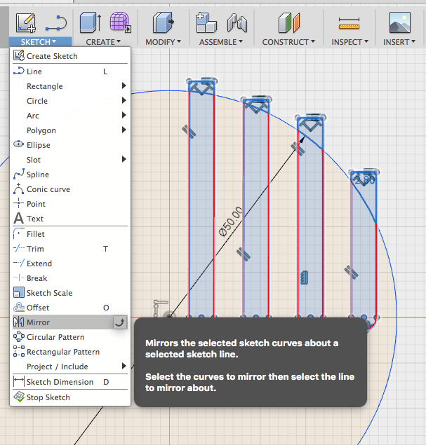
Now, the parametric part: Choose Pattern in Toolbar Create\Pattern. A window will pop up and you have to choose the faces you want to multiply. Then you have to choose the axis or the line as a constraint. May be you have to hide the body to be able to choose a axis like below.
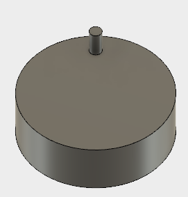
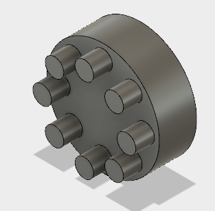
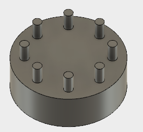
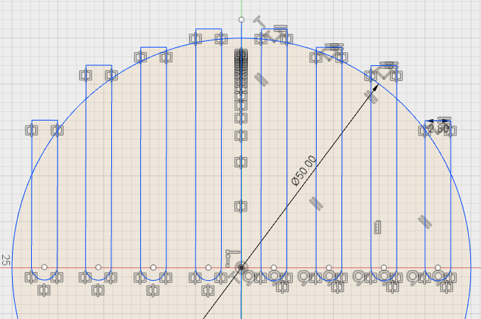
After creating multiple constraint pins, you can change there geometry only by changing the expression in 'Change Parameters'.
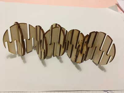
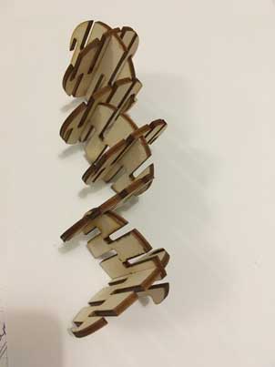
Press-Fit Kitt
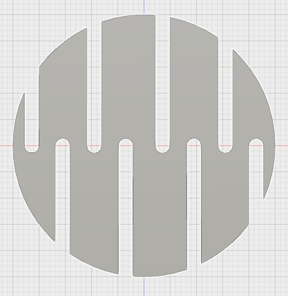
After investigating the characteristics of Zing´s laser-beam I decided to creat a parametric circle as basis for a press-fit kit. The clue of parametric design is, that all connected lines change in subject to one changed line.
Because of the dimensions of the laser-beam I reduced the slit width from 3mm to 2,80mm.
Sending dxf-file to Visicut
I deleted superficial lines in sketch layer and with by the right click on the mouse I could save my sketch as dxf-file for Visicut.
Download dxf File for VisiCut
Download File
Download parametric example