}

3D Scanning and Printing

Cura software, 3D modelling with Ultimaker, 3D scanning

Assignments

  • Test the constraints of the 3-D printer
  • Design and 3 D print an object
  • 3 D scan and print an object


  • 3D Printing - Introduction

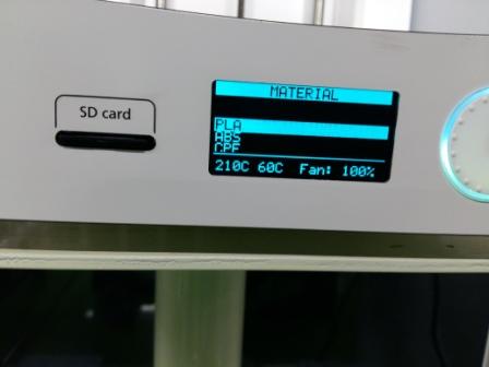
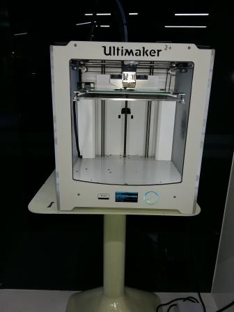
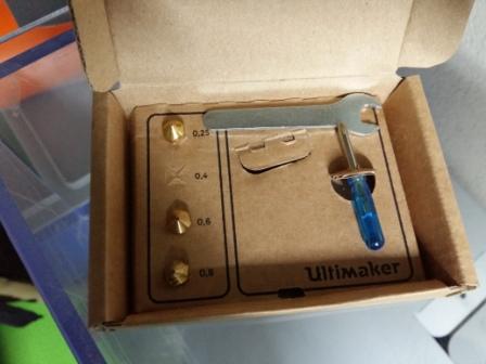
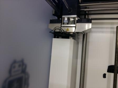
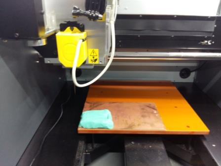
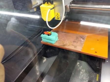
    In our lab we are using ultimaker 2+ 3D printer. It has an open filament system and has easily swappable nozzles of different dia (0.25,0.4,0.6 and 0.8 mm) for detailed or faster print speed. For our testing we used 0.4 mm nozzle which is good compromize between speed and accuracy


    Different materials which can be used

  • PLA - For our lab exercises we predominently used this material
  • ABS
  • CPE
  • Nylon etc

  • Studing already printed 3D models


    Making 3 D printer ready for printing

    Feeding the filament

    Alligning the base plate

  • Step 1 : Go to Maintainance mode
  • Step 2 : Select Build-plate
  • Step 3 : Click on continue and follow the instruction

  • 3D Printer constraints test

    3D Printer tuning parameters

  • Speed - If speed is increase accuracy decrease , if speed is increase according material flow will be required to change
  • Temperature : Nozzle temperature is related material we choose.
  • Buildplate temp : Required so material will stick to the plate
  • Fan speed : Helps in fast drying of material. For intial 5-10 layers fan remains off
  • Material flow : If flow is increase - material remains in liquid form and doesn't get dry and if its reduced material doesn't get deposited properly
  • Retraction : Material is pulled back while moving without depositing
  • LED Brightness : Changes LED intensity

  • 3D Printing

    Designing using Rhino


    As the task for the week was to make something which cannot be made using subtracting method decided to design another object using Solidworks. This job cannot be made subtractively as it has round curved edges which are bended inwards along with an sphere at the centre.

    Designing using Solidworks


    Generating Gcode using Cura


    The job made was 3D printed


    The conclusion was the supports were very strong and difficulty was faced removing them

    So I changed the support Z distance value from 0.1 to 0.3 and again 3D printed the job


    3 D Scanning

    For 3D scanning we will be using Roland MDX 40A Milling machine.

    For scanning purpose we had attached 3D scanning sensor unit(ZSC-1) to the head of the milling machine.

    Specifications of our scanning unit are as below:

  • Max scanning area - 305 mm x 305 mm x 60 mm
  • Minimum scan pitch - 0.051 mm
  • Scanning method - Contacting, mesh-point height-sensing
  • Table load capacity - Max 4 kilo

  • I have decided to scan a toy car as it had lots of details in top surface.


    Below are steps followed while scanning the toy car.

    Initially it takes full 305x305 area for scan. It is needed to be adjust for the area which we need to scan. Or else it will scan for full area and will take excessively high time

    Setting edges in software


    3D scanning the object


    Creation of 3D scan in software


    Final 3D scan object


    Output files

  • 3 D print job solid work file
  • 3 D print job STL file