10. Output Devices
Assignments
- Add an output device to a microcontroller board you've designed and program it to do something
Selecting output Device
Since my final project is smart suitcase, I decided to make a button controlled robot which will move forward, towards left or towards right as per the inputs from switches.
Later I will prepare Ultrasonic modules & its output will be used for controlling the motion of robot.
So I am going to control two geared dc motors.
Design the board as per my requirements
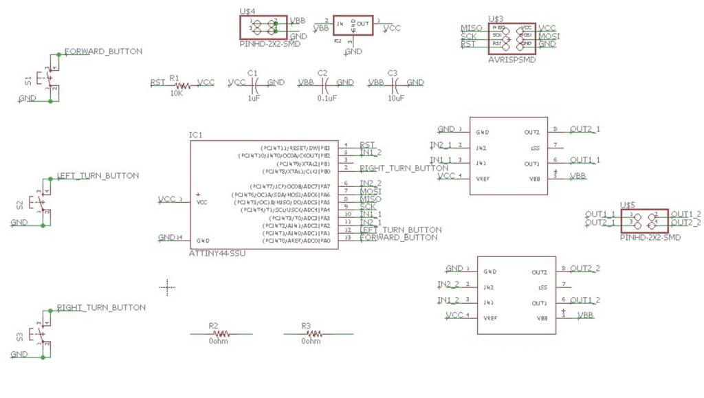
I studied the circuit given on Fab Academy page for controlling DC motor. After studying the datasheet of A4953, I came to know that I will have to use two H-bridge ICs A4953 for controlling two motors.
Also, I decided to use three push button switches as input - 1) for Forward motion 2) for Left turn 3) for Right turn. I decided to use Attiny44 internal pull-up which can be activated through sftware. Hence I did not connect any pull-up resistor.
Creating Schematic & PCB layout in Eagle.
First, I prepared schematic in eagle.
Next,I set track width & clearance under DRC rules. Then I prepared the PCB layout & exported its monochrome png image.
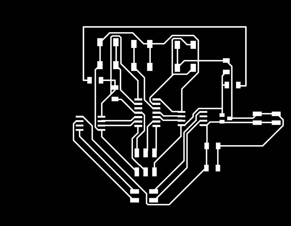
After this, I prepared board outling & exported monochrome png image of the same.

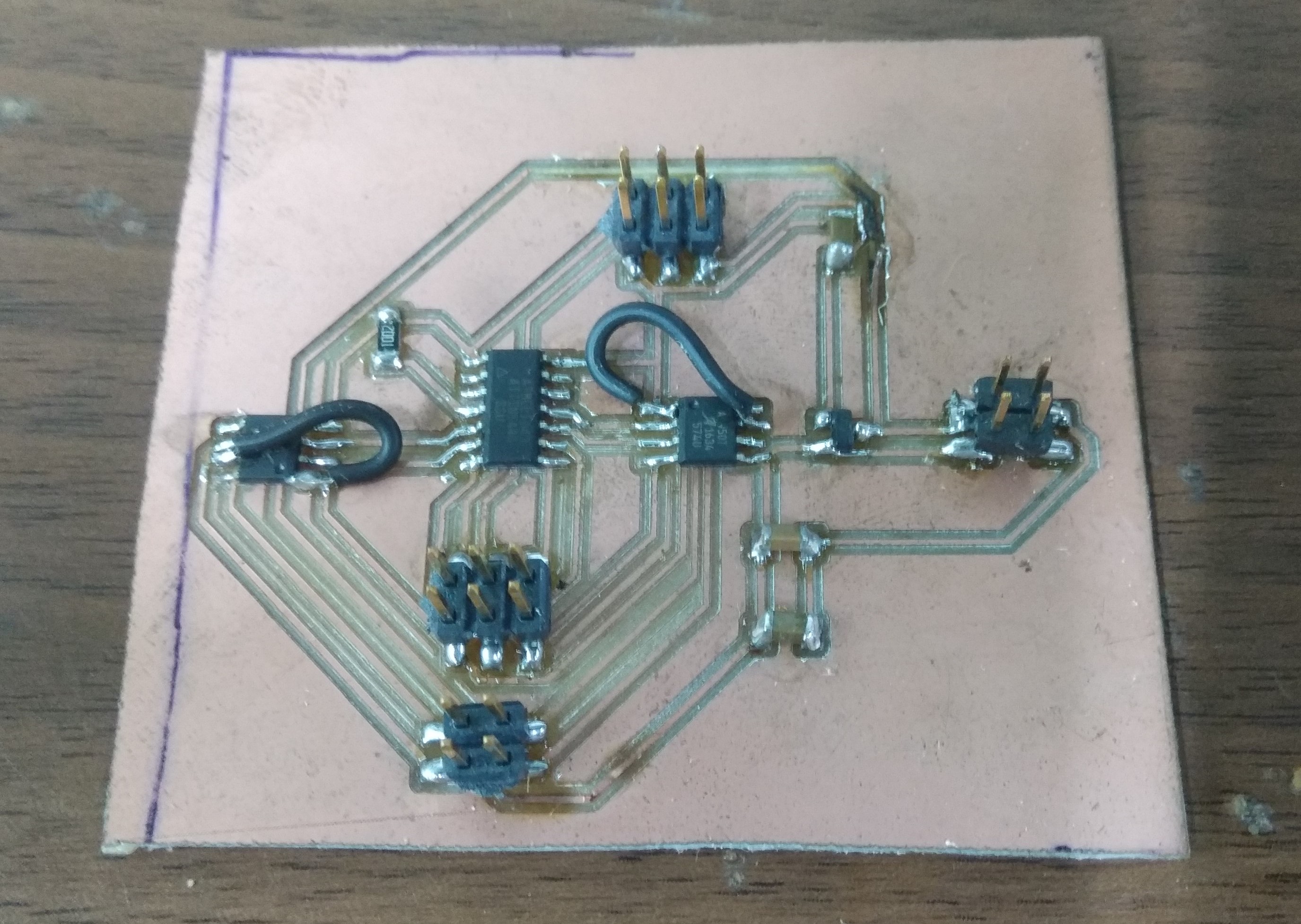
Milling the PCB & soldering the components on the board
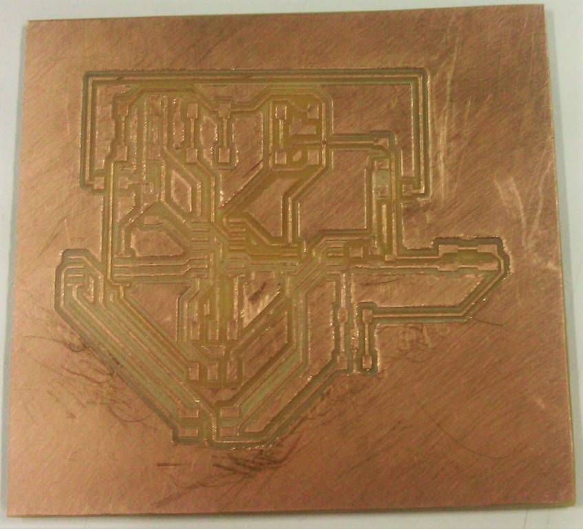
Next, I milled the PCB on Modella MDX-40.
Then,I soldered the components on PCB.
Programming the board & making the dc motor work
We have used H-bridge motor driver A4950 for driving the dc motor. First, I read the datasheet of this motor driver to understand what inputs should be given to it to control the motor.
Here is the code written.
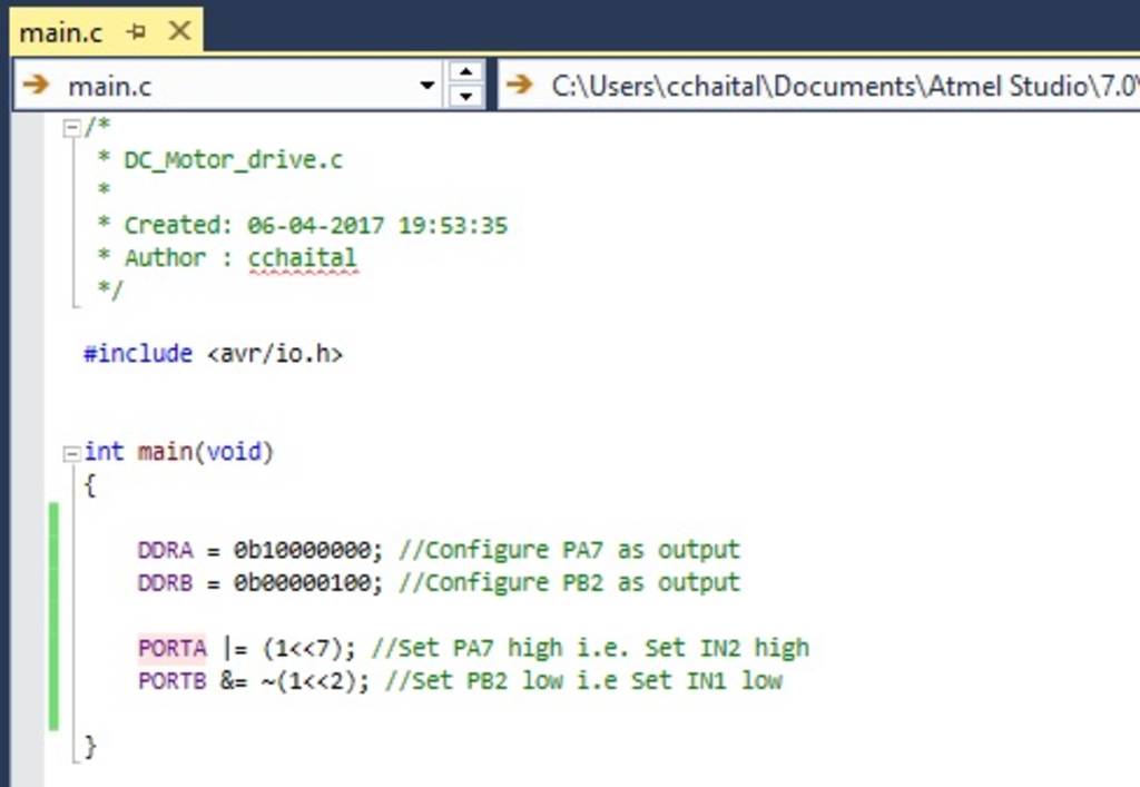
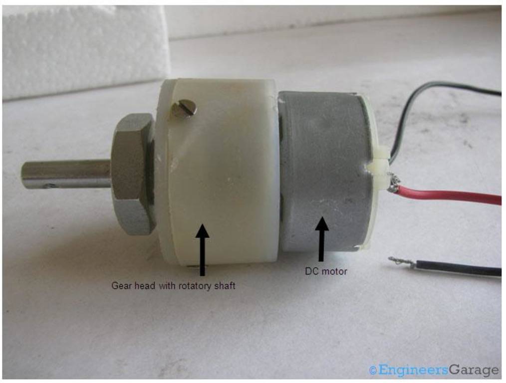
We did not have geared dc motor in our lab. So just for testing I took a 12v dc motor.
Then, I programmed the board but the motor did not work.
First I thought that there is something wrong in my code. So, I went through the Neil's code & rewrote my code. In neils code, PWM signals are provided to Input pins of motor driver while I was giving the constant signals to those pins.
Here is the updated code for diving motor slowly in forward direction.
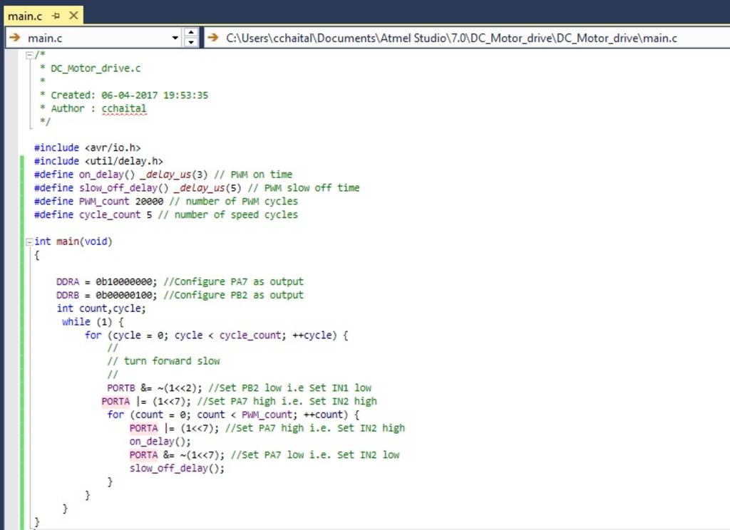
But still, the motor did not work.
After few hours of struggle, we came to know that in our design we have kept LSS pin of A4950 floating. (we have not connected anything to this pin).
In Neil's design the pin was connected to ground.
The same was also mentioned in datasheet. But mistakenly, we missed that while reading datasheet
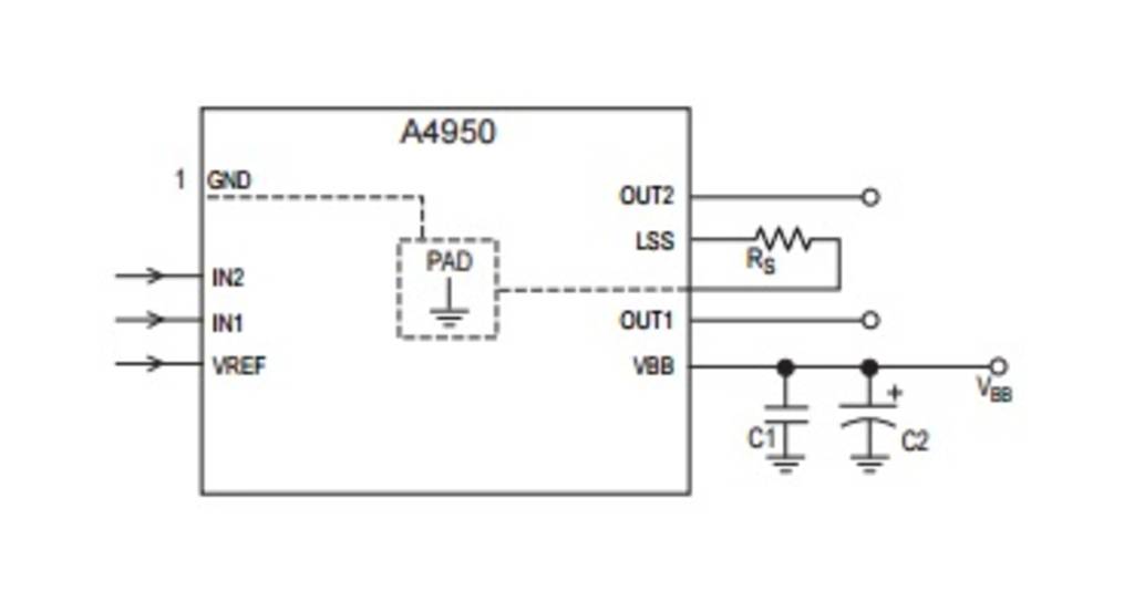
So,after this I made this connection (LSS to ground) using the wire.
And finally the motor worked.
Here is the output...