
_Final Project_DIS/ORDER
_Introduction
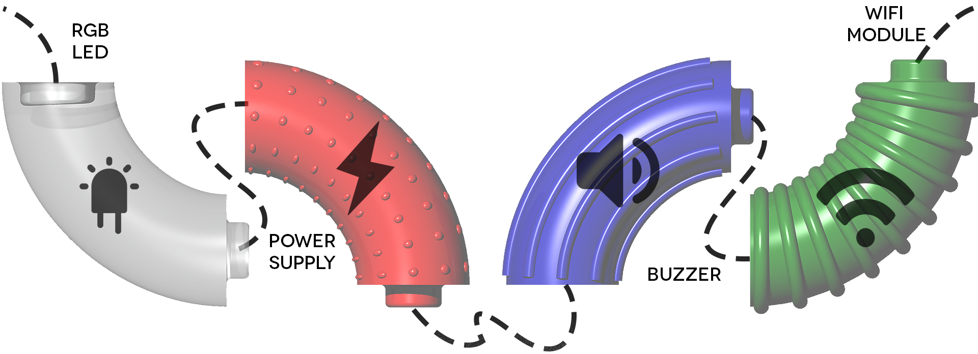
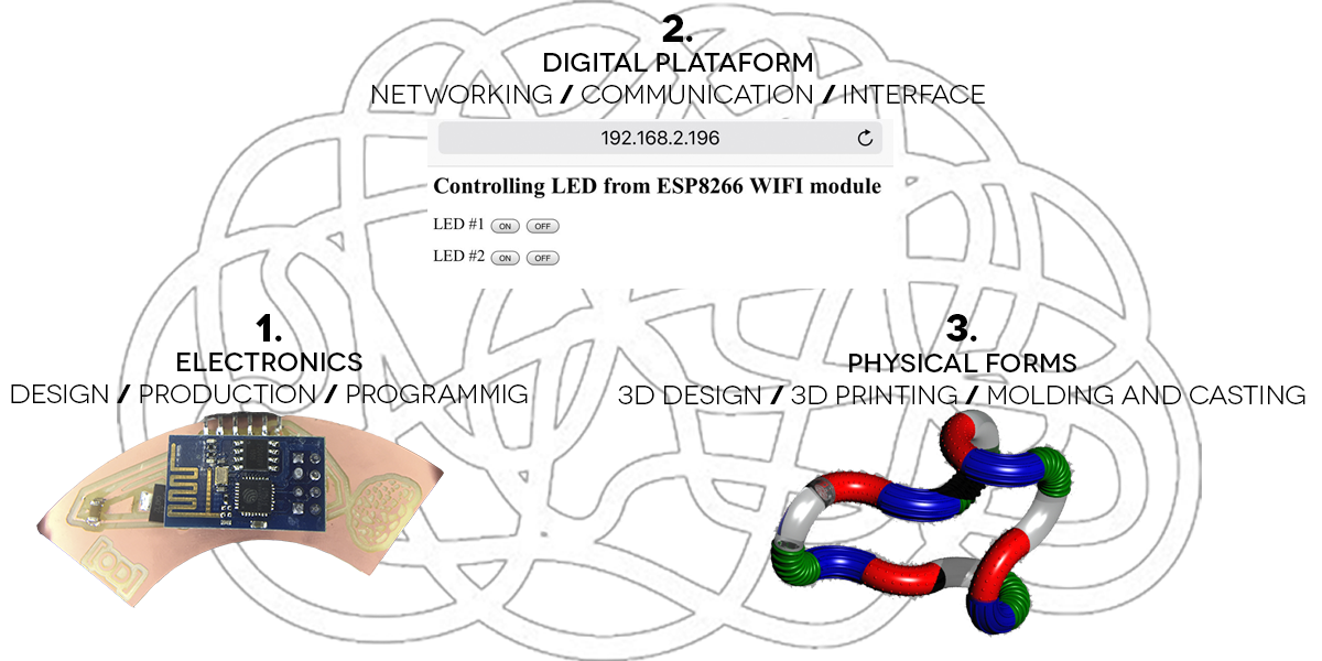
DIS/ORDER is an innovative tool based in digital fabrication, parametric design and ADHD education to make circuits in a funny way keeping focus the kids while providing funds of electronics, robotics, IoT, programming, 3D printing and 3D design. Putting together the four modules will create a circuit which can be control from the digital platform.
_Background
The idea of the project began with an application for a scholarship that comes from the FabLat Kids Network to have the opportunity to study the FabAcademy and develop the project that will continue to promote the work of the Fab Lat Kids network, enhance the value of multiculturalism through technology and contribute to the formation of the emerging generation of leaders of a society with collective, human and shared values. The project must be aligned with the vision of FabLat and for the benefit of the Fab Kids initiative to reproduce it in each local fab lab.


I am also working together with a friend who specializes in children with special needs on how to start generating inclusive workshops for the network but mainly on those children who do not have a "special need" but who for some reason are not considered within the average.

_Workflow /Step by Step
What is the deadline? How much time do I have left?
What tasks have been completed, and what tasks remain?
How will I complete the remaining tasks in time?
What has worked? What hasn't?
What have you learned?
Bill of materials
License

_Project Development
_Electronics
DIS/ORDER prototype contains 4 first modules that snaps together to create a basic circuit, each one contains specific components for make it work independently but communicate each other by serial communication.
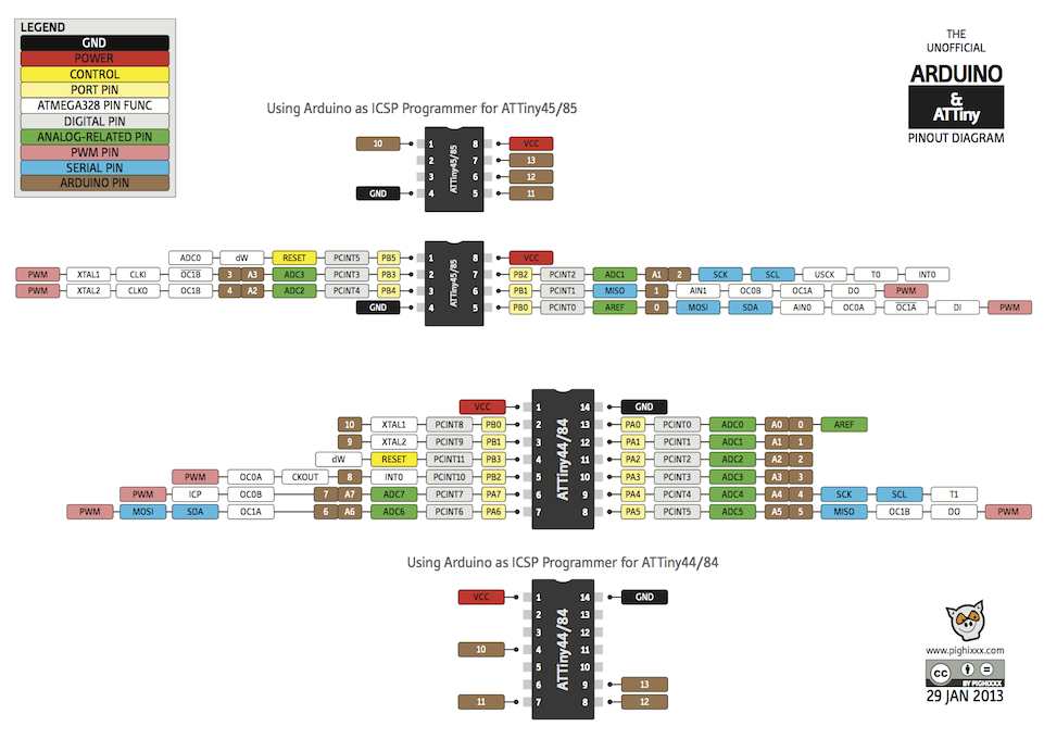
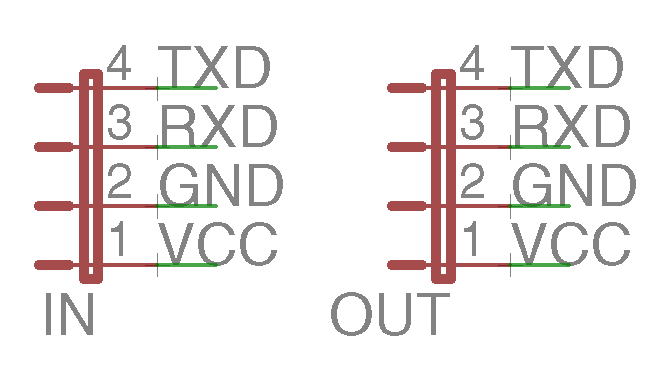
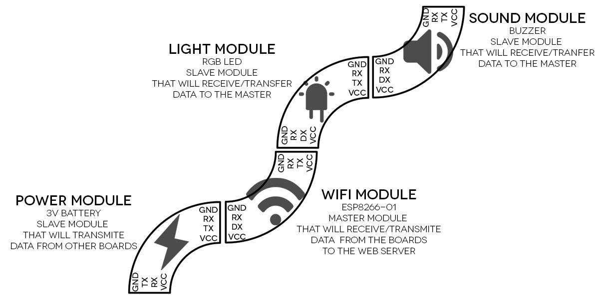 Then to obtain the serial communication, the plates that are using an ATtiny 45 will define the pins 2 (PB3) and 3 (PB4) as TX and RX consequently in all the boards.
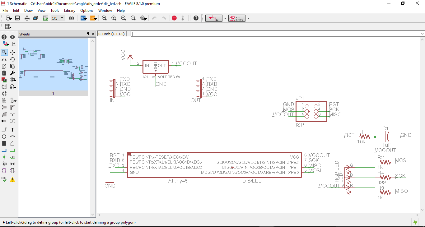
DIS/LED (light module) is based on hello.RGB.45 board which contains the following components:
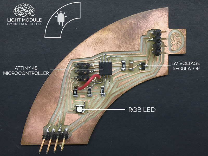 I add two jumpers on each side of the board for making the serial communication with the others boards who will be connected. Each cathode of the LED is connected with one pin of the ATtiny for controlling each color, the common anode is to GND.
 This logic will be in all the boards.
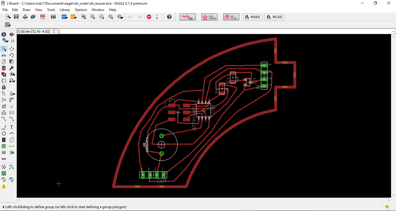
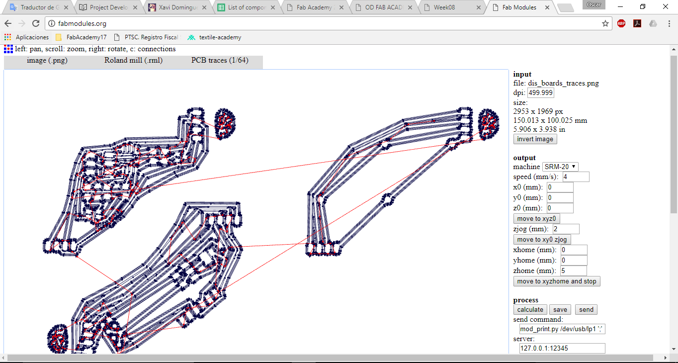
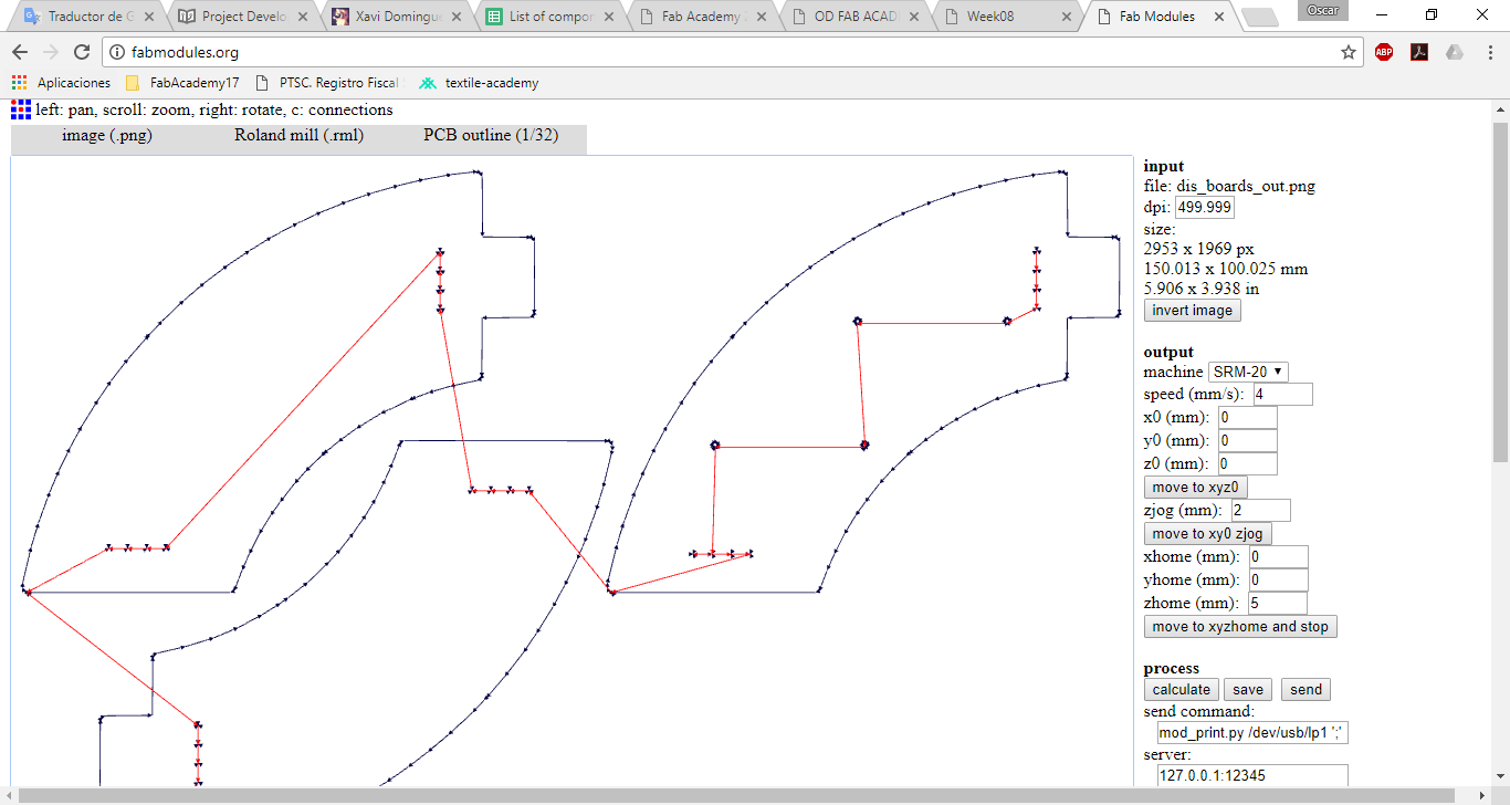
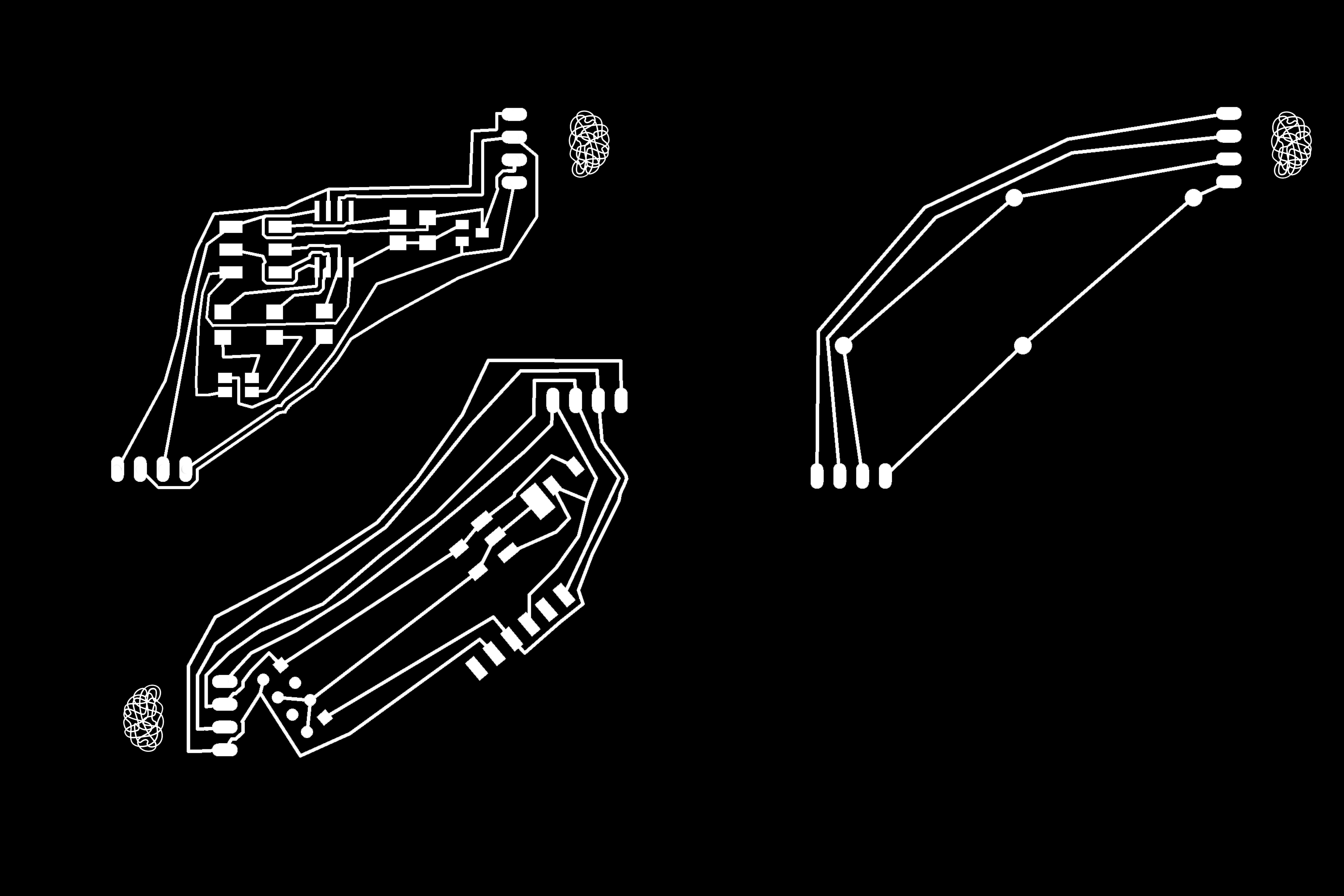
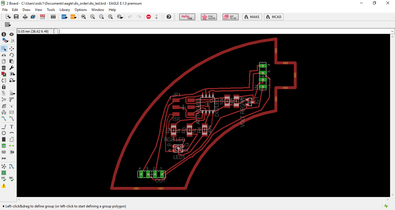 The outline have 1mm of width and the traces 0.35mm in the boardview.
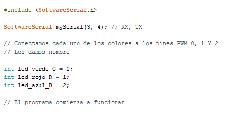
 For programming DIS/LED using the SoftwareSerial library I have to define PIN 3 and 4 as RX/TX and PIN 0 to green, PIN 1 to red and PIN 2 to blue as the design follows.
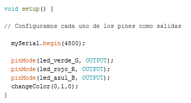
 Then I put the baudspeed at 4800 (as it follows for the other boards and the WIFI speed flash for having the communication) and define each pin as an output.
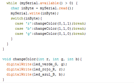
 Finally I made the variable for changing the color sending commands to the serial port through the FTDI cable defining g as Green, r as Red and b as Blue. This later will be usefull for the web interface.
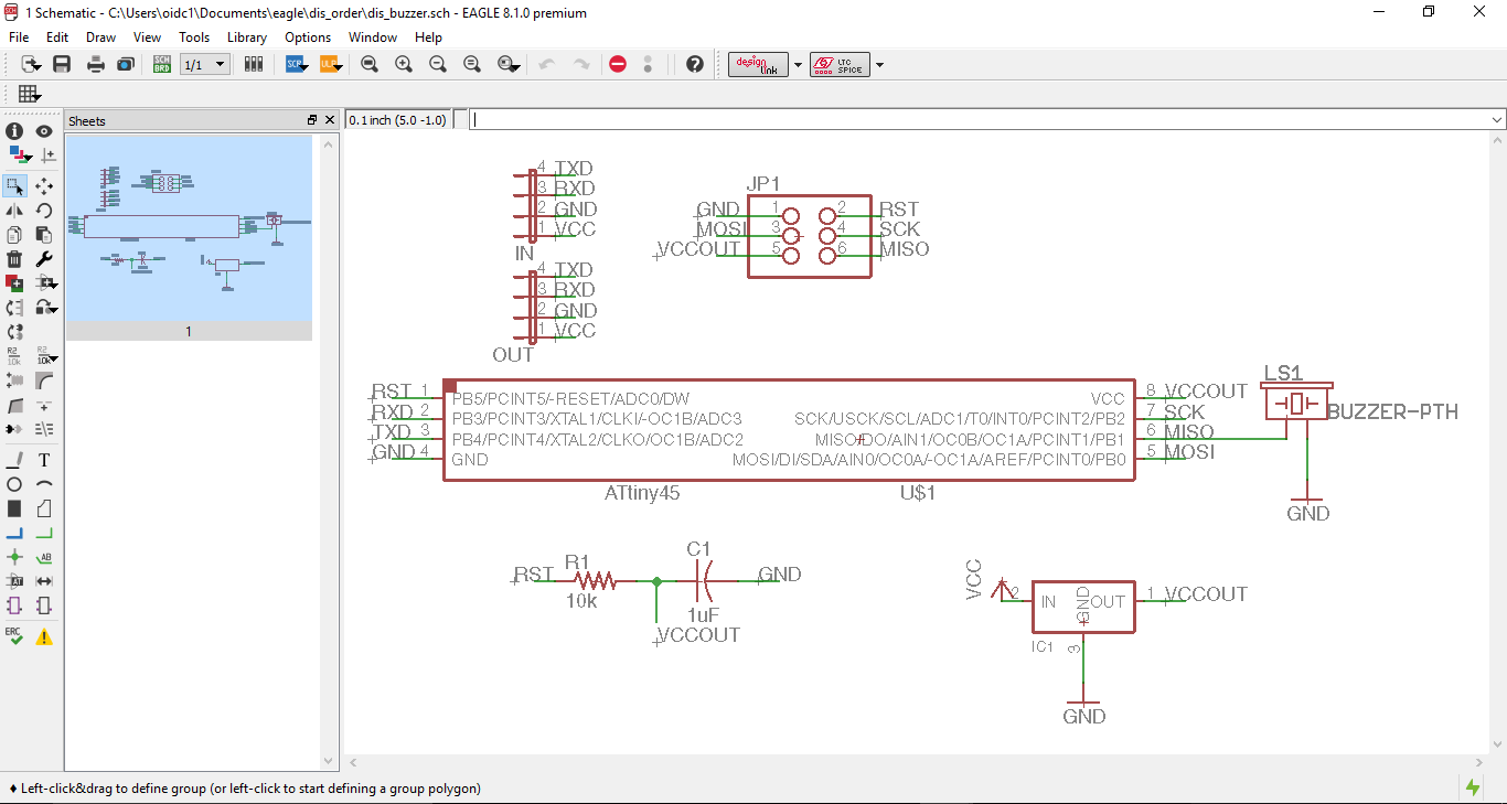
 DIS/BUZZER (sound module) which contains a piezo buzzer as an output and contains the following components:
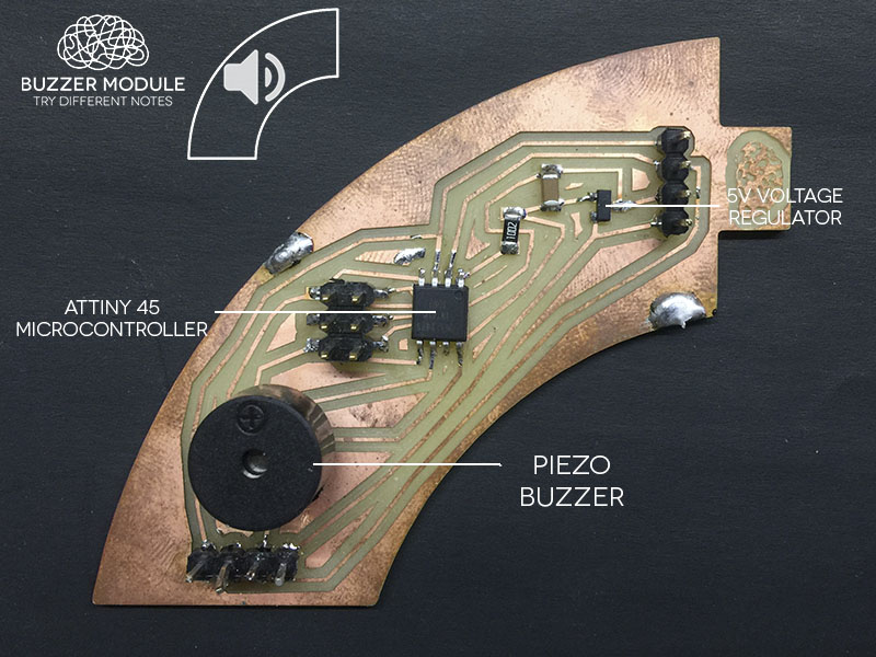 Following the same logic as the past board and just need to connect one pin of the ATtiny 45 to the positive pin of the buzzer and the negative to GND.
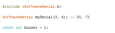
 For programming DIS/BUZZER I use again SoftwareSerial defining PIN 3 and 4 as RX/TX again and define PIN 1 to the buzzer.
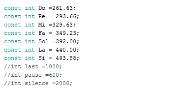
 For controlling a buzzer I wanted to make the musical notes like a piano so each note have a different frequency in Hz that I have to define in the code as it follows in the musical scale.

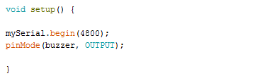
 Defining the baudspeed and the pin as and output.
 Making the variable for the serial communication with each case for different note.
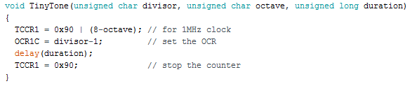
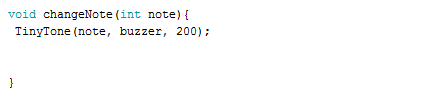
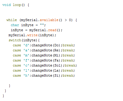 This work good but I had a problem that when I send more than 2 commands I got interference and sound more than one note at the time. So I checked for Tinytone that is a special library for managing frequency for buzzer for ATtiny's microcontrollers; the library controls the counter and define better the octave for musical scale.
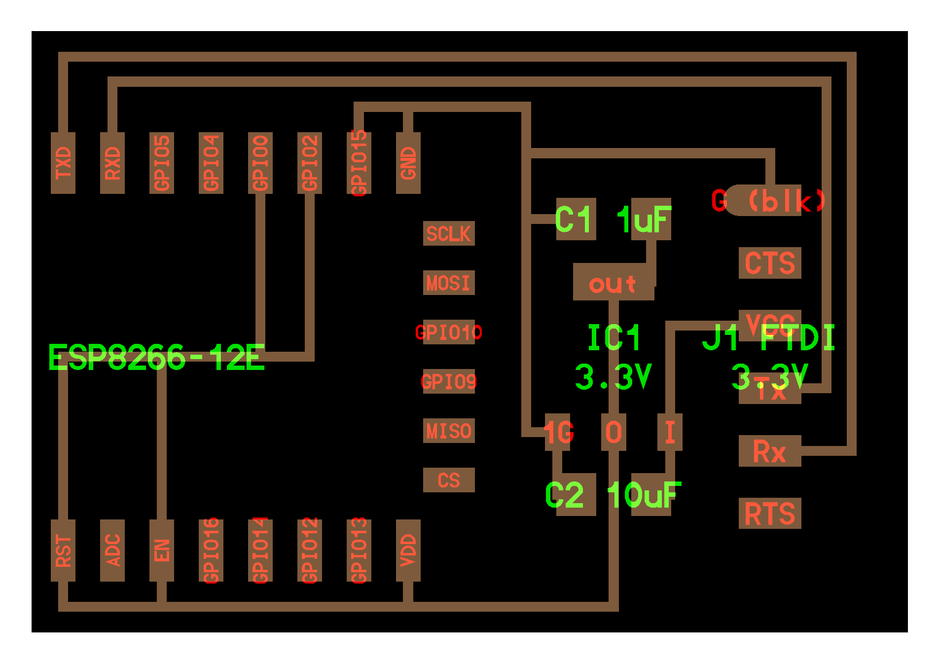
DIS/WIFI (WIFI module) is based on hello.ESP8266-12E.ftdi board but in this case I use the ESP8266-01 instead of the ESP8266-12 because I already worked with this one. This board creates it's own network as a hotspot and interfaces the outputs of the circuit, contains the following components:
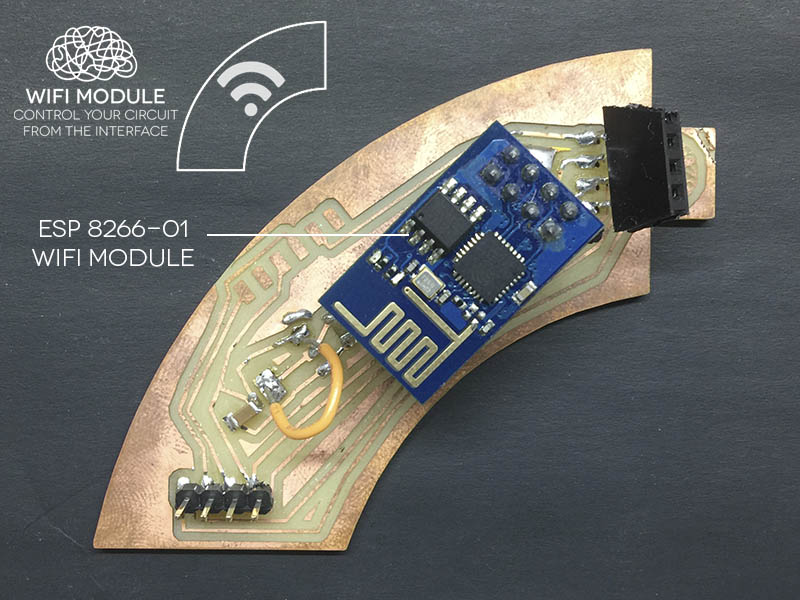 In this case as I worked on week 16 with the ESP8266 module, I skip the voltaje regulator because the module was working perfectly with 6V without problem and when i put the voltage regulator do not work and the FTDI cable because before I put into the board the ESP8266 I upload the sketch and then just make it work in the board (also for fitting in the case of the module).

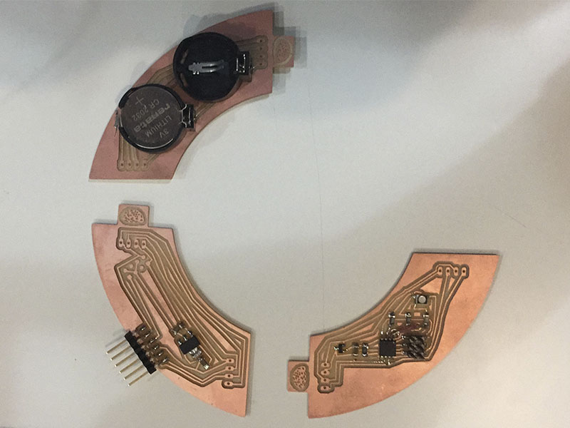
DIS/POWER (power module) which contains the following components:
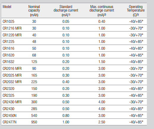
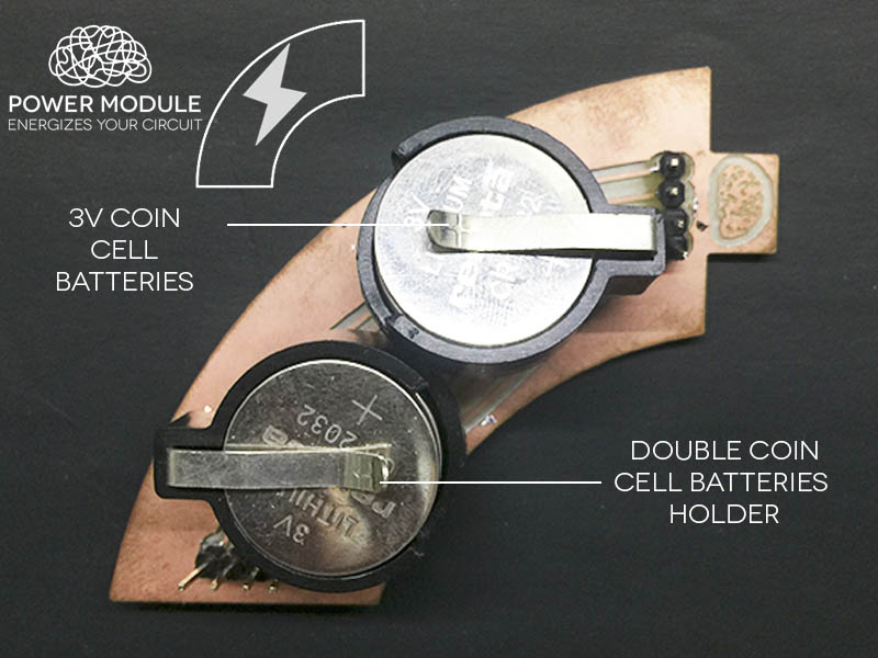 In this board the batteries are connected in serie for having 12V for all the boards for running all the components, the 4 batteries give in total 900mAh.
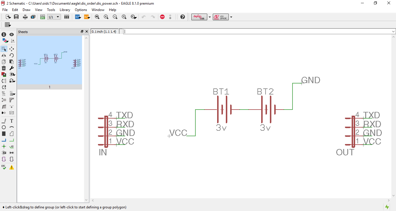
 For having in serie the batteries I connected one GND and one VCC of each battery together and then the other two to out GND and VCC as the image.
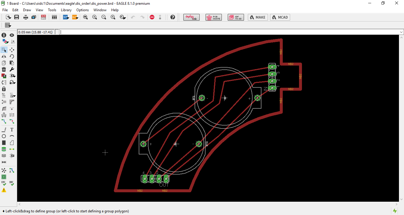
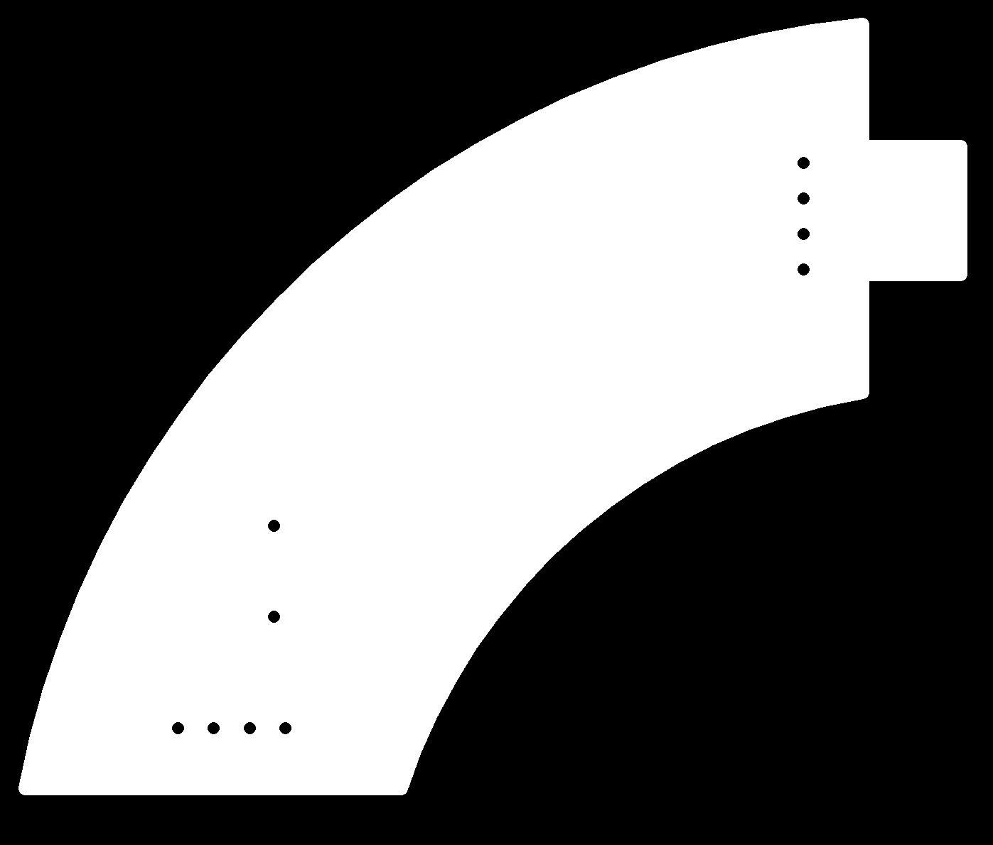
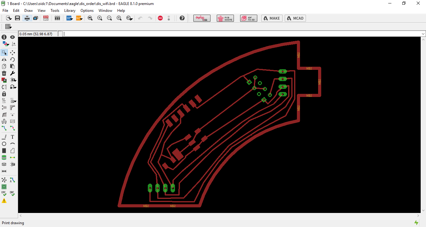
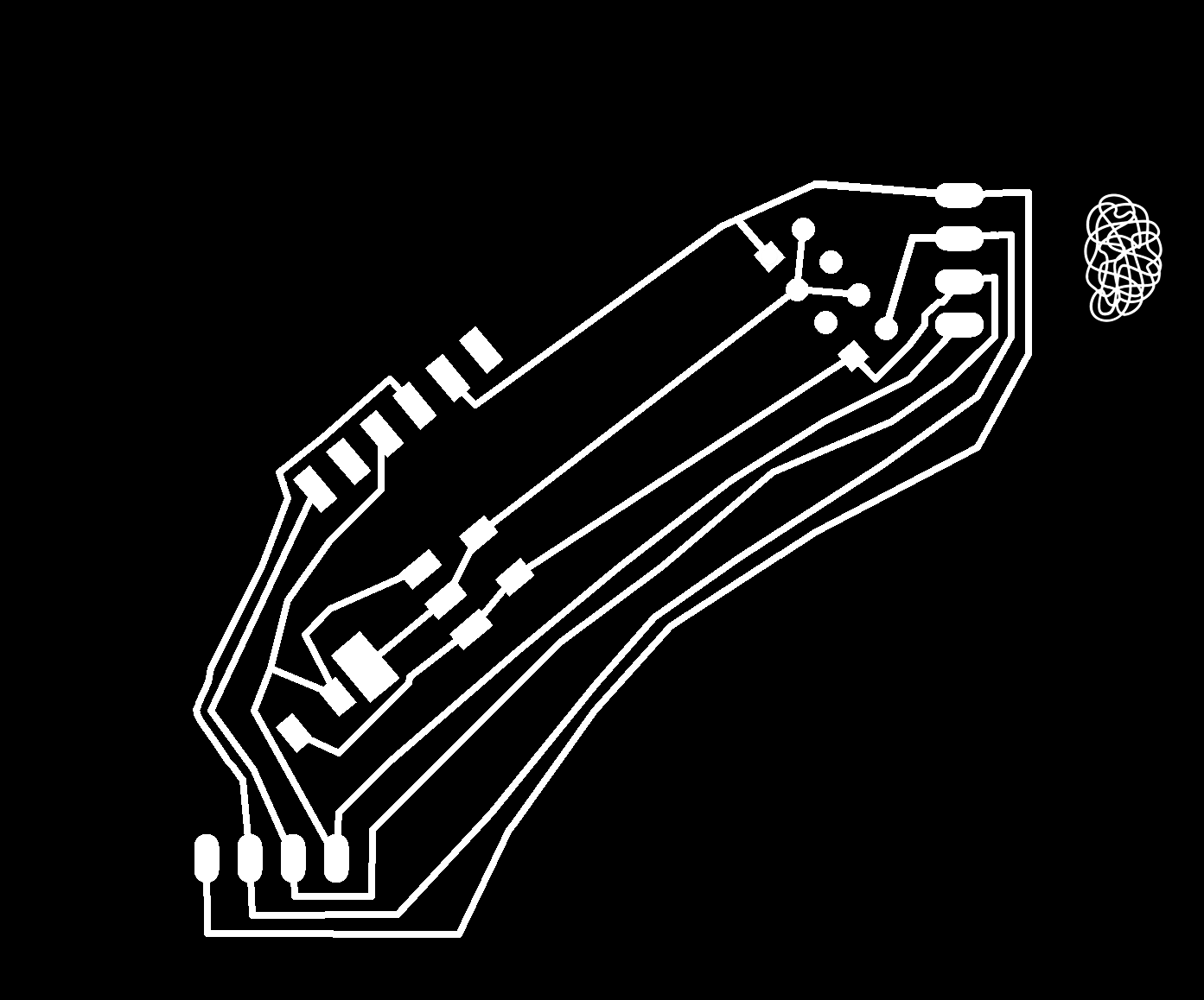
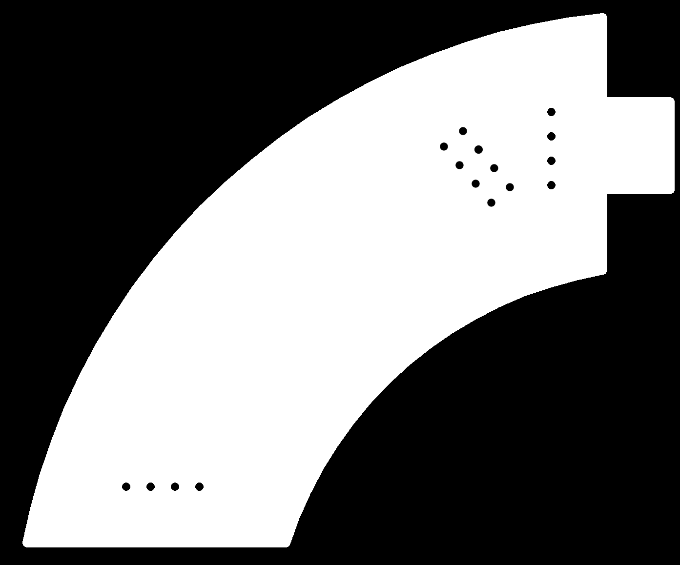
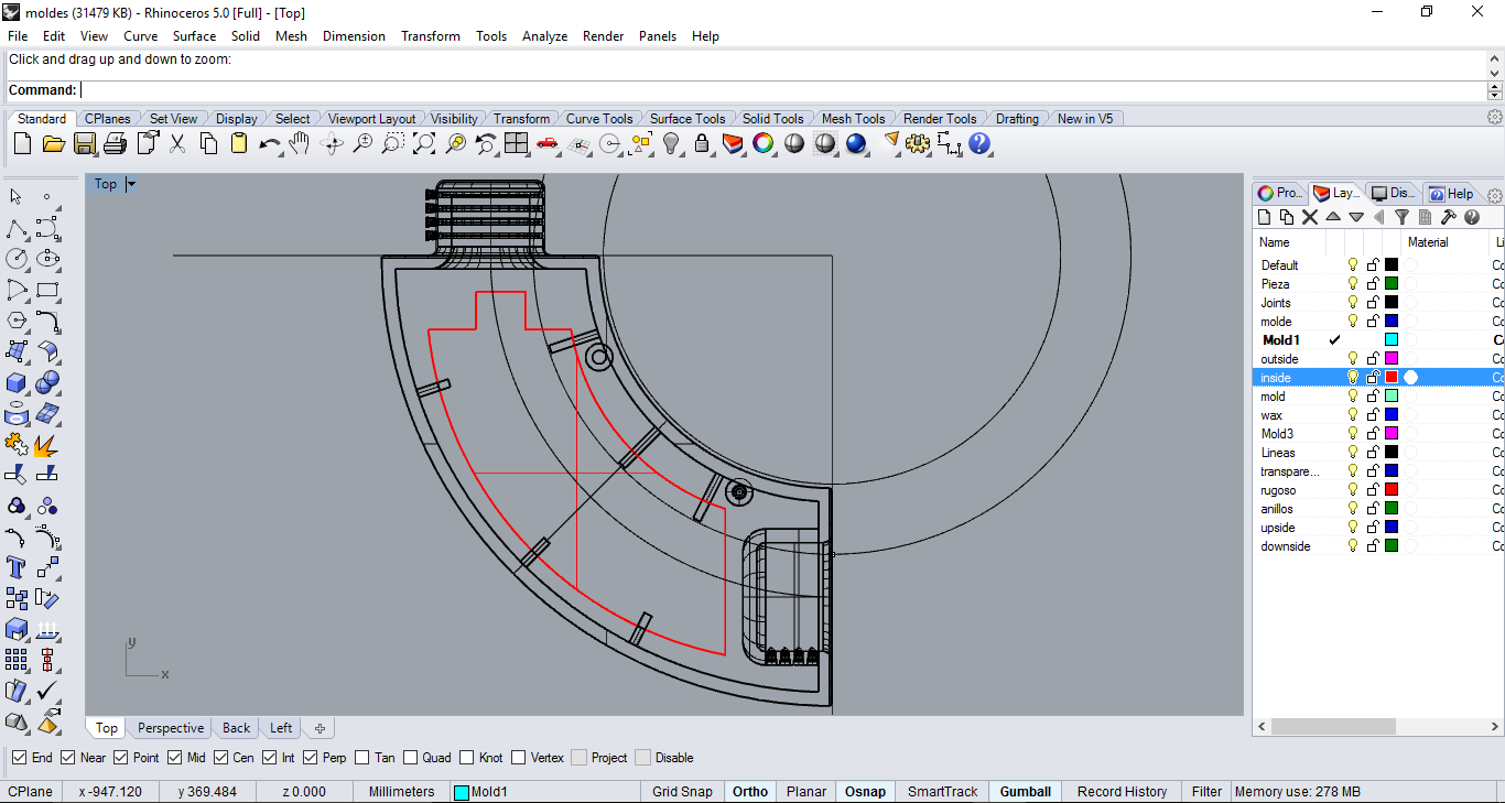
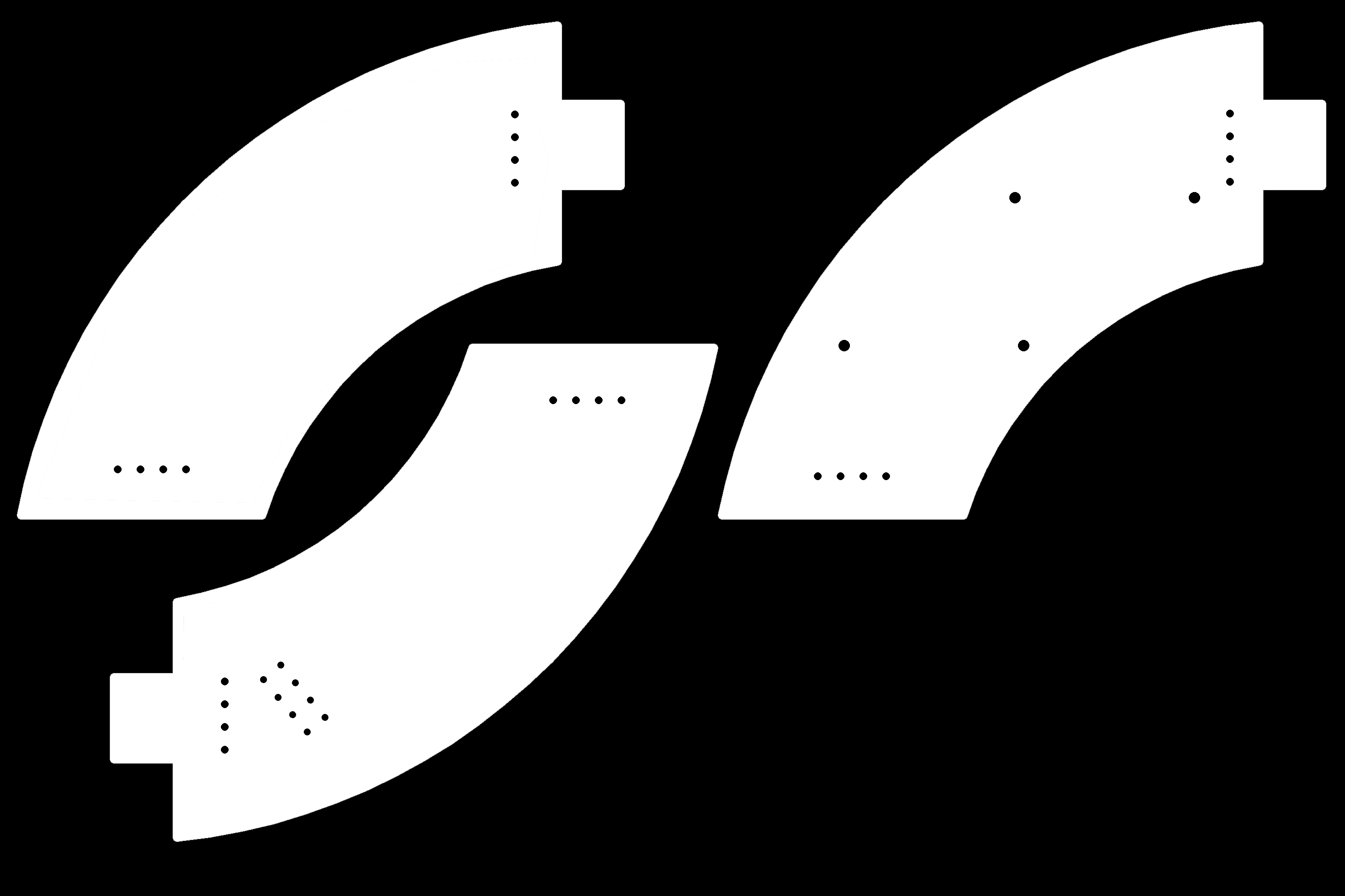
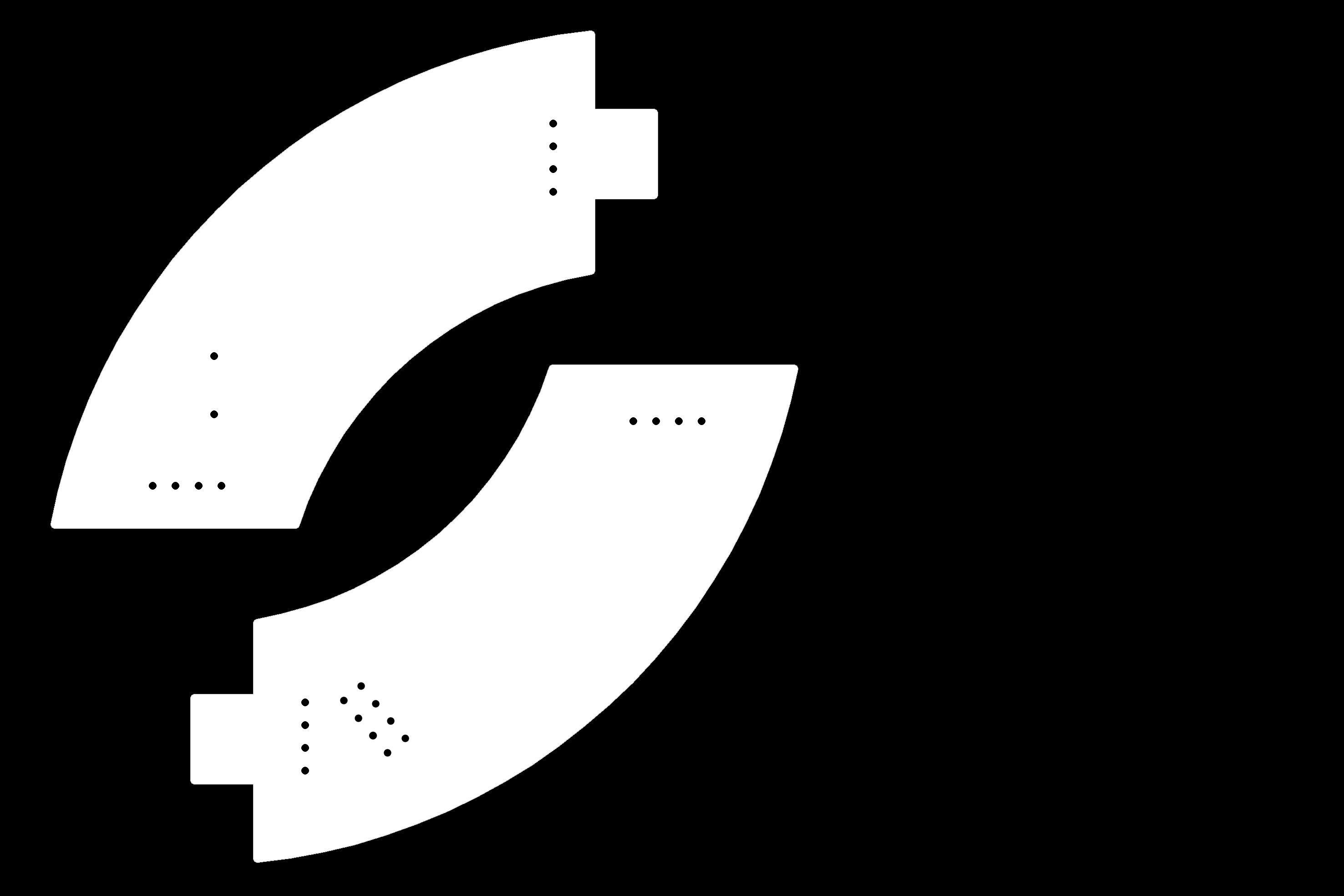
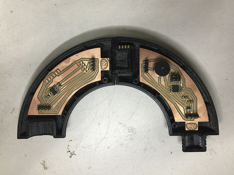
The shape of the boards were imported to Eagle as DXF file exported from Rhino 3D model of the module that is in the inside of the case.
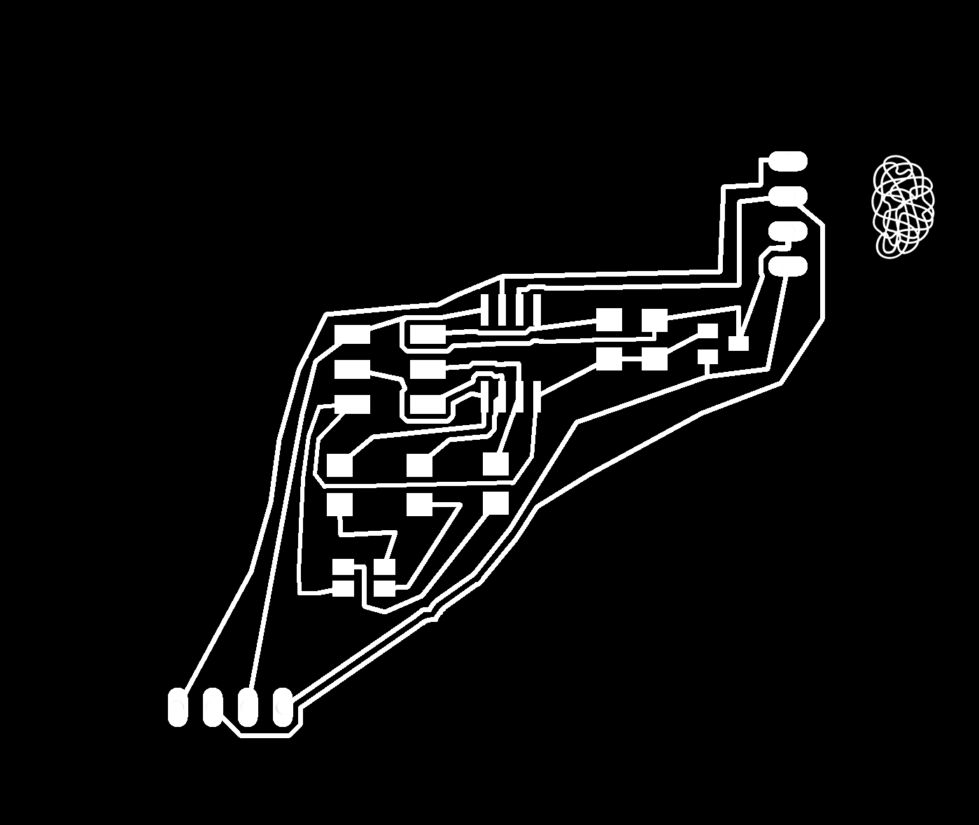
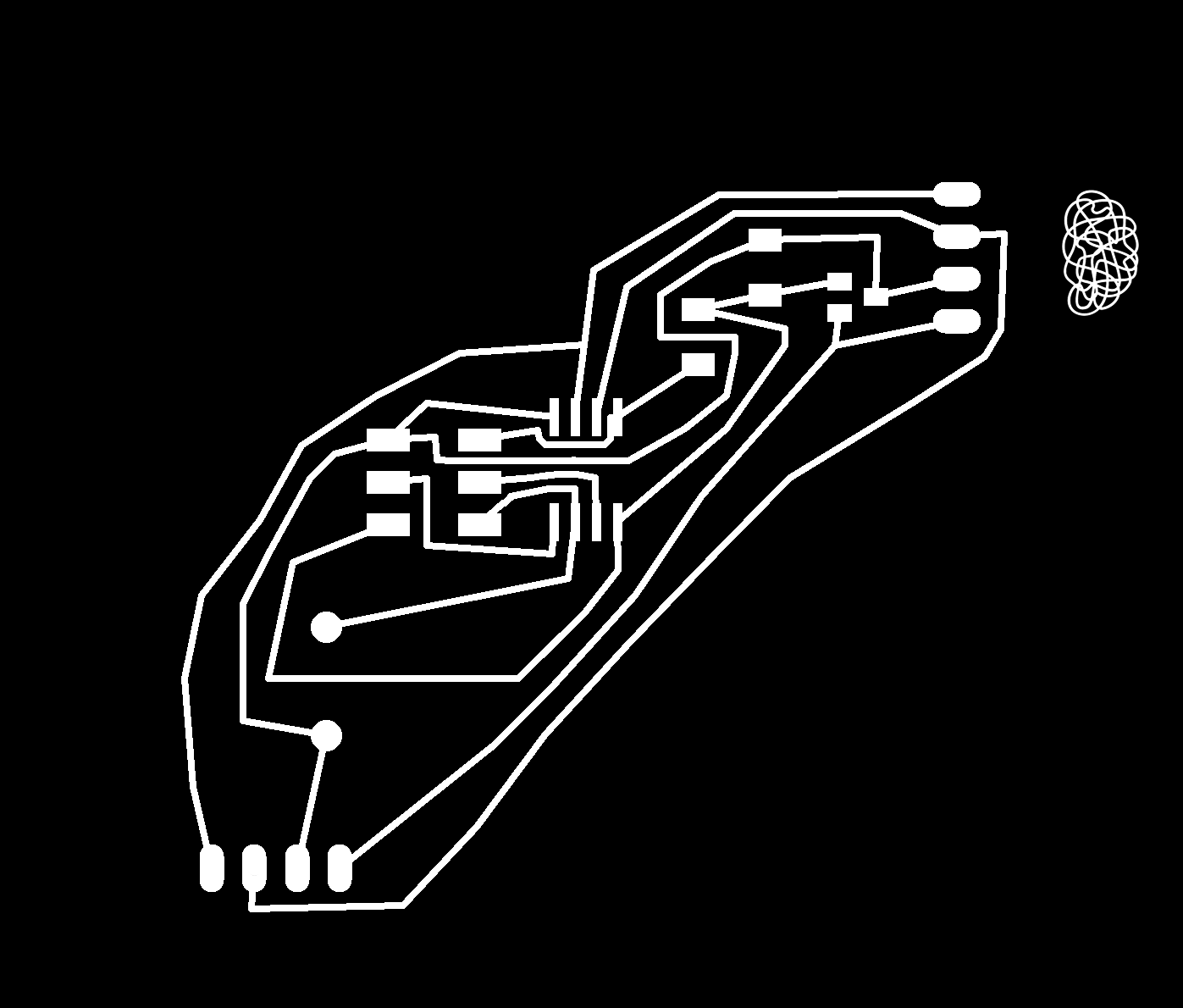
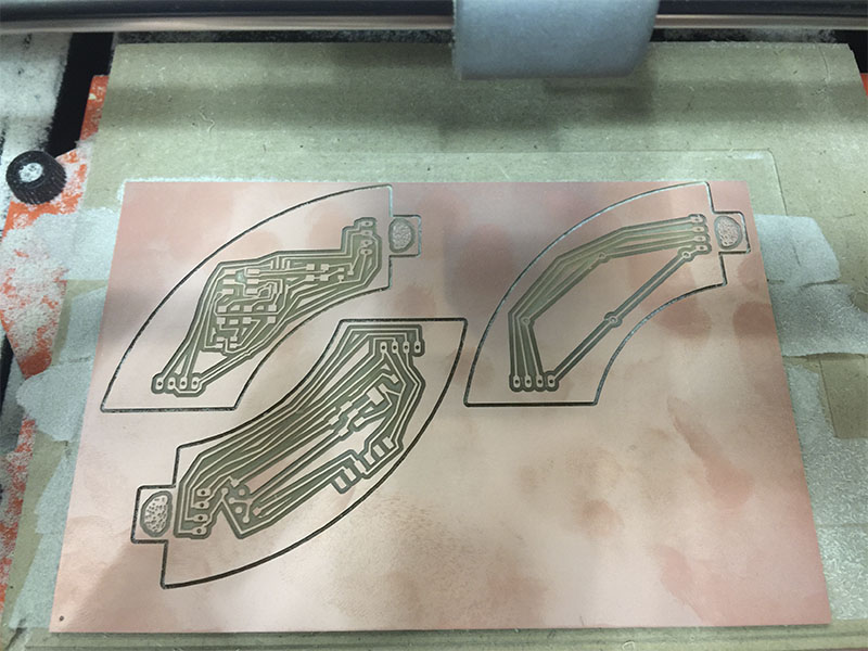
This time for milling all the boards I put all the files in the same PNG file for sending at the same time all the boards to the Monofab and also making holes into the boards.
 And the buzzer board and the correction of the WIFI module.

This work was based on the following processes learned:
_Digital plataform
As I said in the electronics part, the WIFI module works like the master that send/receive data from the other slaves modules; between the modules the communication is serial and for the digital plataform is a wireless communication with the ESP8266-01 who creates its own hotspot with an IP.
For programming the ESP01 I followed the same process as week 15 in order to flash and programm the module, but in this case I wanted to create my own hotspot because this type of wireless communication doesnt need to connect to another WIFI network around so it keeps open the communication in everywhere.
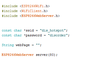
First, include these three libraries of the ESP8266 and define the name of the network and the password; the webserver will always work on port 80.
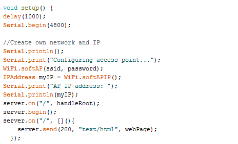
Later I define the communication speed at 4800 (NOTE: this have to be the same as all the other boards) and the other variables of the serial.
Then I define the cases of each board in the WIFI module for sending the request for controlling the outputs (as remember in the programming of the LED and the buzzer I define cases for each reaction).
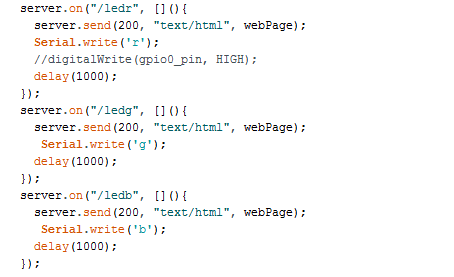
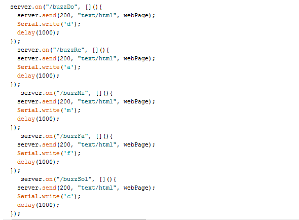 With this the ESP01 will send these commands to the boards through the network and this orders will go to microcontrollers.
The HTML web page is code also in the Arduino IDE in just one string. NOTE: As the module creates its own network and doesnt use other networks with internet connection work with different parameters for uploading images on the web and the fonts.s

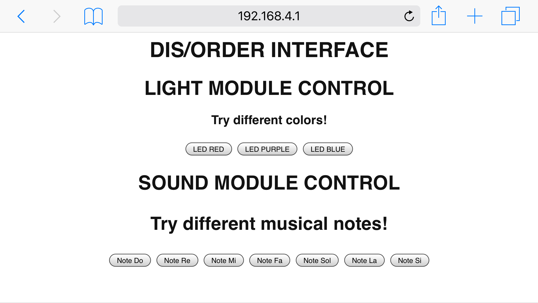
After upload the sketch and make the module work I connected to the "dis_hotspot" network putting the "disorder" as the password and enter to the browser with the IP that is in the network. This IP will be the same always 192.168.4.1, the webpage code creates the buttons when those are click will send the request for the differents functions of the outputs.
This work was based on the following processes learned:
_Physical forms
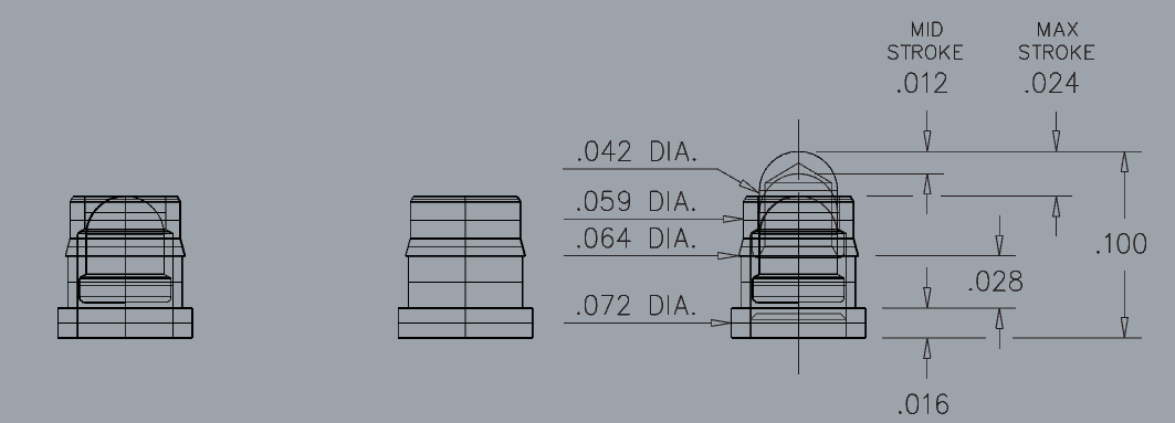
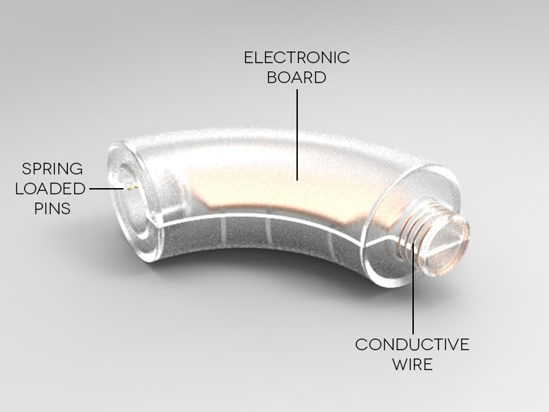
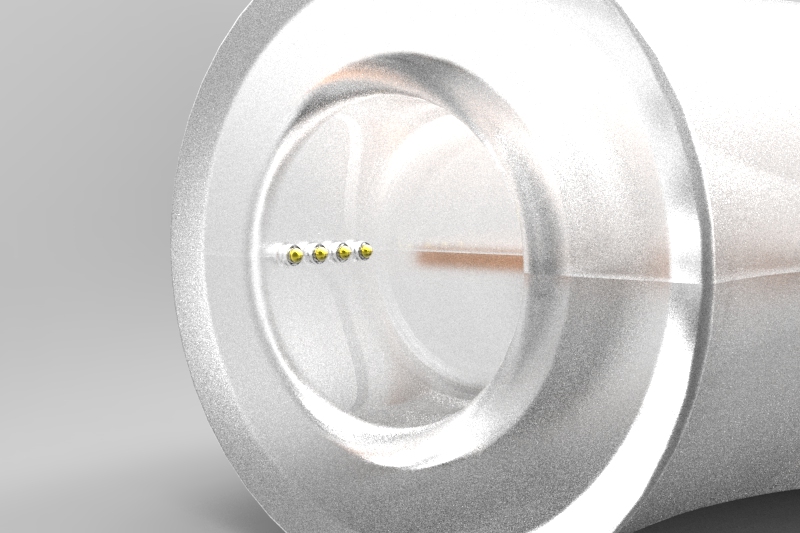
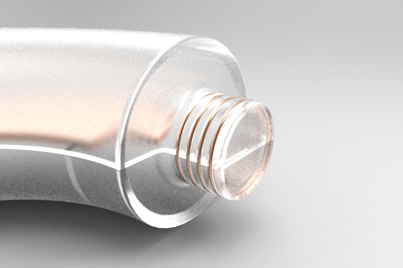
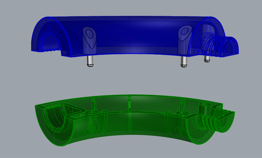
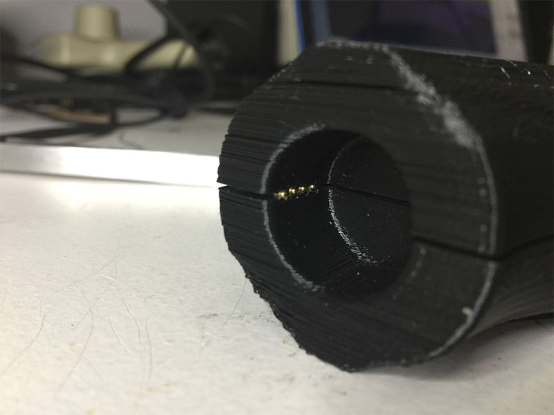
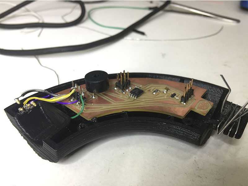
For designing the cases of the modules as the first idea of the project based on week 2 but for this work of the final project I made some corrections in the dimensions of the cases (following the dimensions of the electronics to fit inside) as well the size of the male/female joints for using the spring loaded pins (pogos) for achieve the 360° movement of the circuit while been connected.
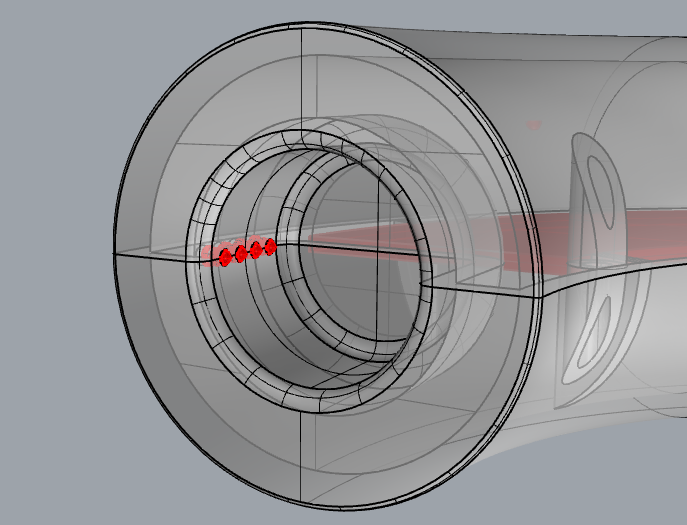 The idea of using the pogos is that this will be into the female joint between the two cases of the module and those will touch in the other side the conductive wire that will be around the male joint.
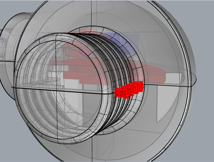
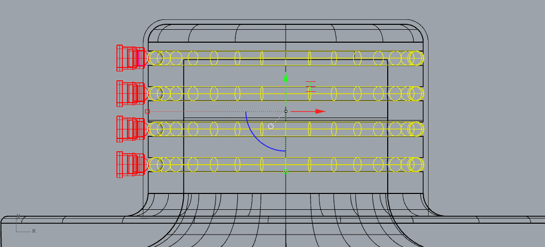 For the spaces for fitting the pogos I create the pogos 3D model and put it in the case, as well the spaces for the conductive wires were design with tubes around the male joint.
 Also I add some supporters and male/female joints inside the cases for put it together without glue.
Later I created the two sides molds for molding and casting the parts, following the same process for creating the molds as in week 12, but in this case I have a doubt about the definition of the pieces for the pogos and conductive wire so I decide to 3D print the molds.
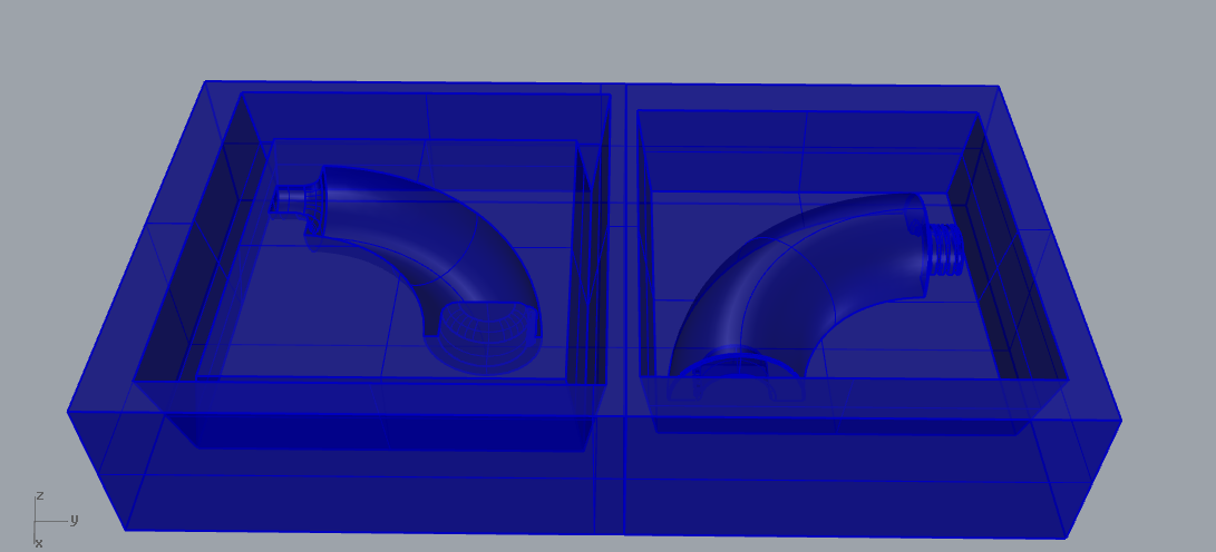 For matter of time I didnt follow the molding and casting so I decide to 3D print the cases.
I printed the cases on the Ultimaker with the following parameters:
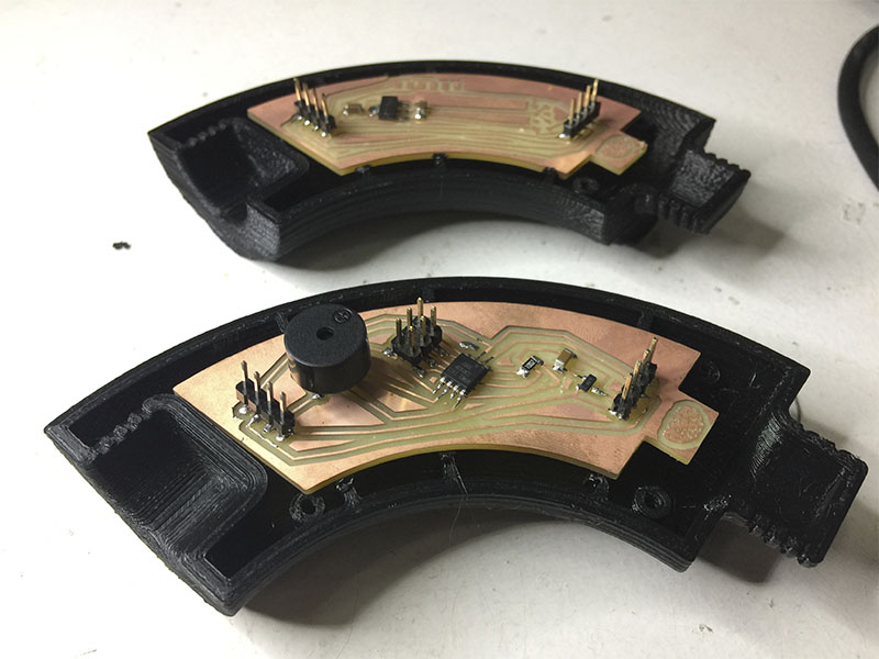
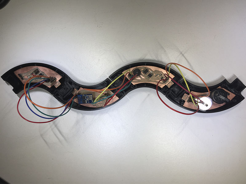
 For matter of time and the way that I have to manage to connect the pogos in each module I leave the pogos and make it work all the circuit with jumpers inside the cases.
This work was based on the following processes learned:
_Next iteration
_Incomplete tasks for solve
_FILES
All the files for the final project are available to download here