Assignment


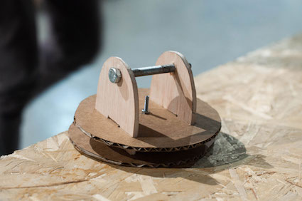
The first step this week was learning about a prototype to undestand what the best geometry for the movements of our robot is.
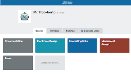
Our first meeting was to organize the job, and to share the ideas that we had in mind. TRELLO is a project manager app used to organize everything. It is very useful to share our resposabilities, but our job was to do everything as a team.
There are some examples we found about ideas regarding our wish.
![]()
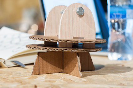
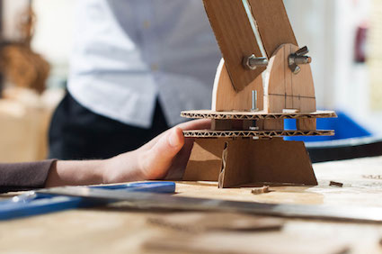
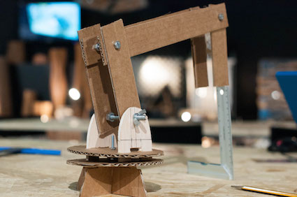
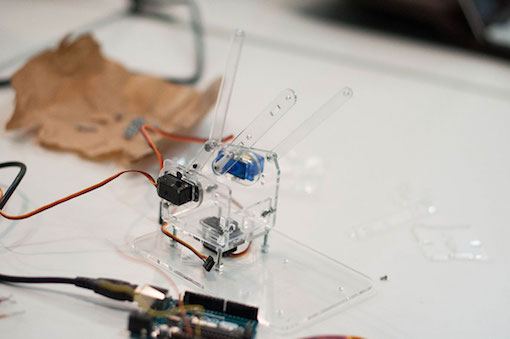
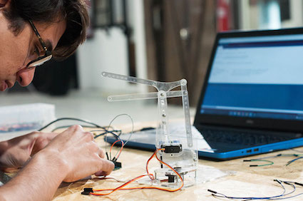
That same afternoon, we made the PROTOTYPE.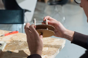
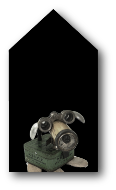
Documentation about our Group Assignment in the FabLab Barcelona. We decided to build a 4-axis Robotic Arm to serve us drinks ;)
Then with the FabLab manager, Martin, we had a group consulting.
The last friday we went to the study from Cit and Andres, where they are developing some robots that reproduce the movements of the dancers, is a very interesting experiment, because they have a pieces of clothes with sensors that are used for the dancer and with radio waves are transmitted and reproduced by the robots.
This meeting was very importat because was like other way to understand how the robos works, is an other mechanics idea, the movements are more modular and when you undestand how works the movementes about the geometrys and mechanics everything is different.
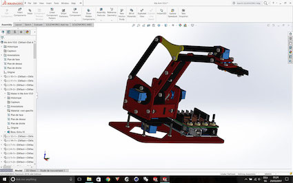
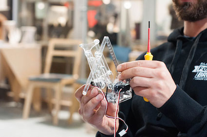
We looked at a lot of different robot arms and decided to build one that is similar to the MeArm tiny 4-axis robot.
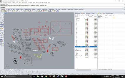
We started disable the 3D file in solidworks, but found out later that it would be easier to open it in rhino make2D and lay all the parts on the stock for the lasercutter. Nie part about the file was that it already had all the simulation for the movements in solidworks. That comes in handy for the future when we want to buuild our own arm.
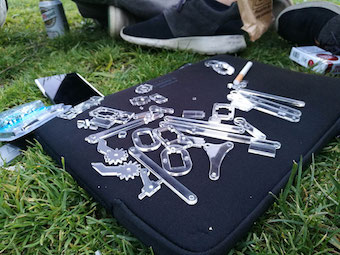
It was Saturday so the fablab was closed. We decided to go to the FabCafe, a place where you have to see when your visiting barcelona. They have a 3D printer and a lasercutter and for a small amount of coins we let our parts cut out of 3mm acrylic glas. After that we meet in the park and wanted to assemble the robot, but found out we would need the servos to assemble it. At least we found most of the screws we need in a hard ware shop.
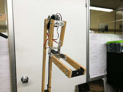
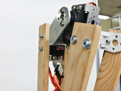
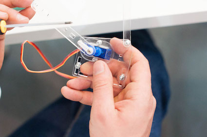
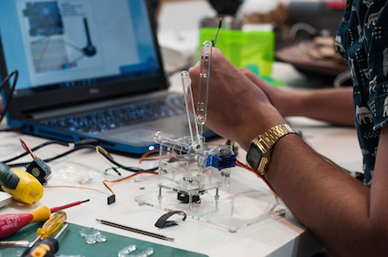
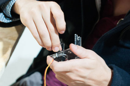
Om monday we found some servos in the lab and started to assemble it. It was difficult because acrylic glas in 3mm likes to split, so we lasercutted a second board just to be sure that we will have enough parts. Then we found out that a couple of the servos are broke so we needed to buy new ones.
Or pulse-duration modulation (PDM), is a modulation technique used to encode a message into a pulsing signal. Although this modulation technique can be used to encode information for transmission, its main use is to allow the control of the power supplied to electrical devices, especially to inertial loads such as motors. Wikipedia
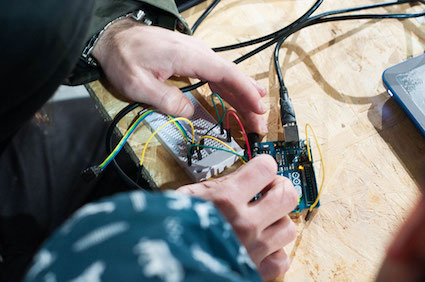
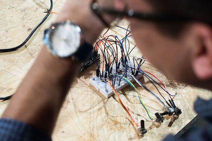
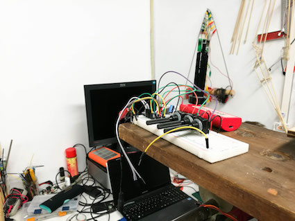
This is the simple connection diagram for controlling a microservo of 5v with a potentiometer with the Arduino UNO, the microservos use VCC, GROUND and Data (any PWM pin as I learned in Output week).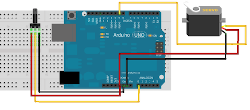
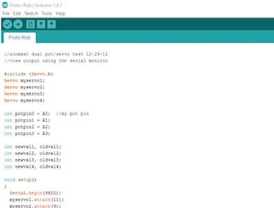
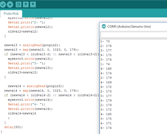
And the code that I started to use in Arduino IDE:
#include
Servo myservo1;
Servo myservo2;
Servo myservo3;
Servo myservo4;
int potpin0 = A0; //my pot pin
int potpin1 = A1;
int potpin2 = A2;
int potpin3 = A3;
int newval1, oldval1;
int newval2, oldval2;
int newval3, oldval3;
int newval4, oldval4;
void setup()
{
Serial.begin(9600);
myservo1.attach(11);
myservo2.attach(9);
myservo3.attach(10);
myservo4.attach(6);
Serial.println("testing dual pot servo");
}
void loop()
{
newval1 = analogRead(potpin0);
newval1 = map(newval1, 0, 1023, 0, 179);
if (newval1 < (oldval1-2) || newval1 >
(oldval1+2))
{
myservo1.write(newval1);
Serial.print("1- ");
Serial.println(newval1);
oldval1=newval1;
}
newval2 = analogRead(potpin1);
newval2 = map(newval2, 0, 1023, 0, 179);
if (newval2 < (oldval2-2) || newval2 >
(oldval2+2))
{
myservo2.write(newval2);
Serial.print("2- ");
Serial.println(newval2);
oldval2=newval2;
}
newval3 = analogRead(potpin2);
newval3 = map(newval3, 0, 1023, 0, 179);
if (newval3 < (oldval3-2) || newval3 >
(oldval3+2))
{
myservo3.write(newval3);
Serial.print("3- ");
Serial.println(newval3);
oldval3=newval3;
}
newval4 = analogRead(potpin3);
newval4 = map(newval4, 0, 1023, 0, 179);
if (newval4 < (oldval4-2) || newval4 >
(oldval4+2))
{
myservo3.write(newval4);
Serial.print("4- ");
Serial.println(newval4);
oldval4=newval4
;
}
delay(50);
}
Analyse and solve technical problems.
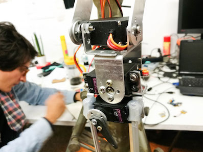
Once all the components were placed and connected we got problems with the movement because it was not too smooth as we want it so Santi tell us that it was because of the "noise" of the voltaje the comes from the USB port so we change to the DC power supply in order to having stable current to provide to the servos.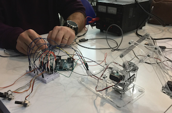
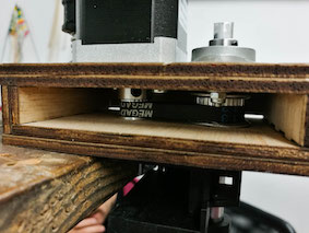
Also, as the week Mechanical design, the joints made by the bolts and the nuts have to be double (or triple) checked to gain good movement of all the joints in the robotic arm.
Opportunities for improvements in the design.
In the Ouput devices week I continued working with the idea of Mr.Rob-berto and improve its automation without using the Arduino UNO and the potentiometers, so I see how to control the 4 servos with an ATtiny85 and then put a joystick in the electronic design of the board.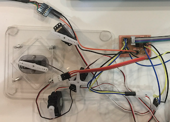
All the files are available to download in