Assignment

This week the idea was to redarw the "Echo hello-word board". This was to learn the differents ways to design boards and circuits. I was using Autodesk Eagle.
This software is an easy way to draw and select the components that you will need for some electronics jobs.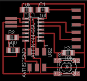
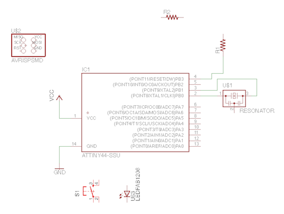
This is the example that we have to follow in order to do our board. Everything is in this tutorialand this is the exaple of the schematic in Eagle.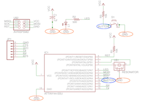
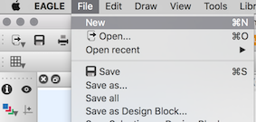
When you open Eagle, do this:
- File; New; Project; ..name..; and then you make the schematic.
In the schematic window you can put the components of the ISP to do the connections. First you have to upload the library from fab to the software. library.
Only drag the new library to the library of Eagle.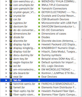
Then, you have to introduce the component.
Now do the connections. The way to know if the connections are done correctly is by moving the components and the wires have to be still connected.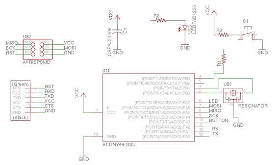
When the schematic is all ready, you only have to press this button and the board appears in the other window where you can create the design. Nothing easy!
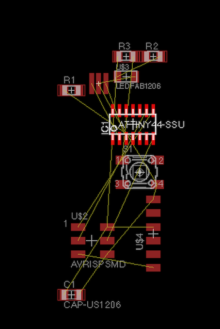
This is the first image that you can see when you open this window. Don't be afraid! Because here everything is out of the layout. You drag all over the layout and start to design.
Set up the clearence, because this is the distance between the lines and change everything from 8.000 to 16.000.
Tried 1 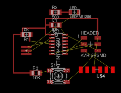
Eagle file
Tried 2 &mesp; 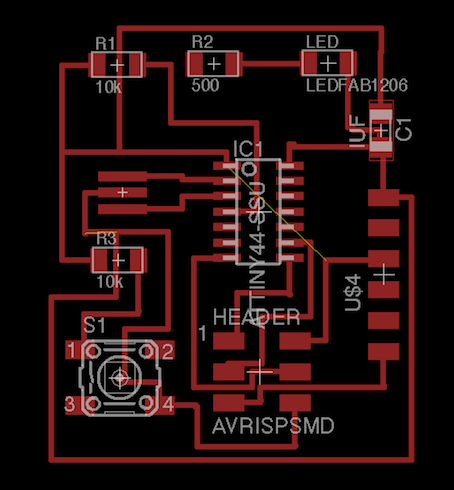
Tried 3 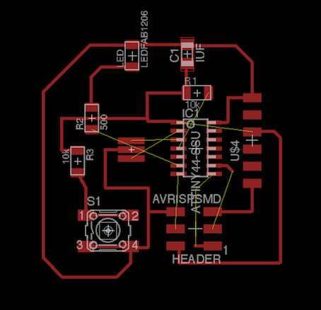
Tried 4 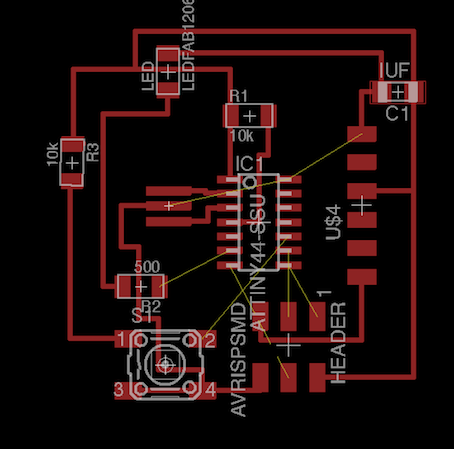
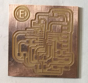
Finally 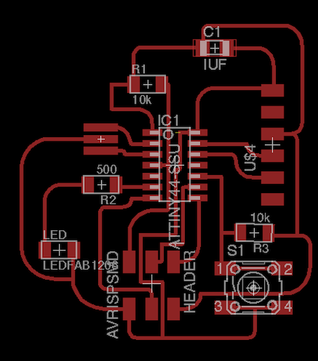
with "BOM" command you export the components list: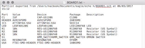
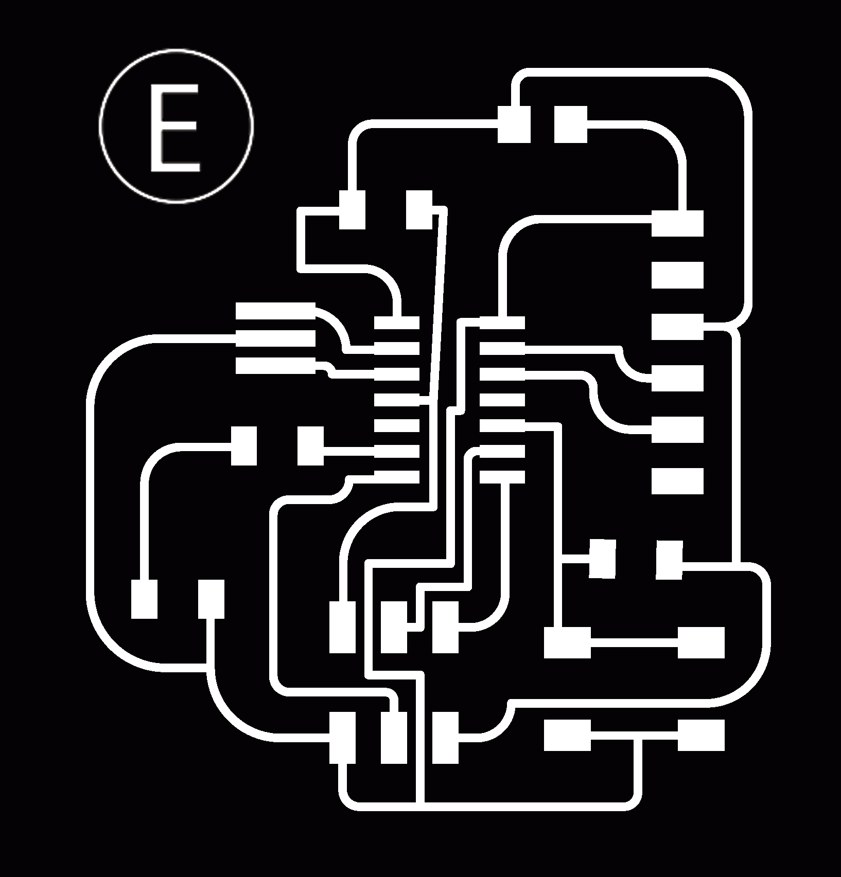
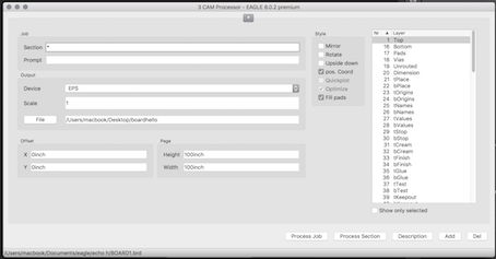
To export the file you have to be in EPS, this is to keep the original sizes because when you import this in Photoshop you will have to create the outline and then export like PNG to create the Gcode in FABmodules.
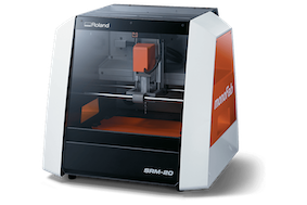
The parameters to cut the board are the same as 2 weeks ago, here are the steps:
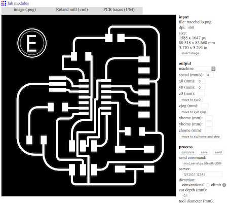
-Input format: image png
-Output fromat: Roland mill
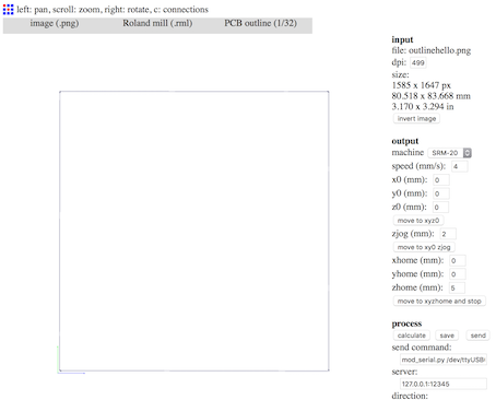
-Process: PBC trace (1/64); PBC outline (1/32).
Traces .Eps
Trace .RML
Outline .RML
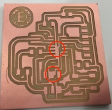
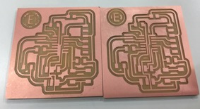
I had some problems with my first cut because the quality of the .PNG file that I exported was very poor and some lines had joinded together.
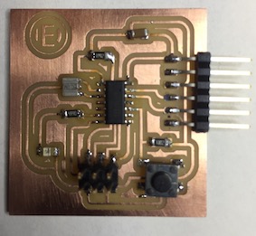
First I did the checklist of the component.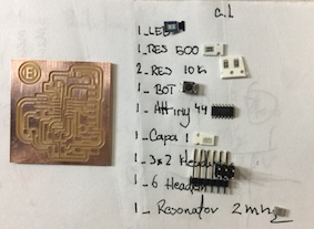
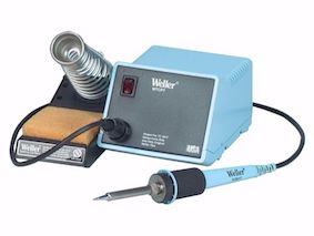
And the last thing was to solder.