ASSIGNMENT 4.
Electronics production.
GENERAL IDEAS TO START THE THING!
I'm new in electronics. It's something I never had time to get into. So I was expecting a huge catastrophe. At the end it was not that bad.
The first part of the assignment was pretty cool. That's something you can get very familiar with, and quite fast. So it makes you feel comfortable with the challenge.
Some of them I already knew. Some of them not. These are my thoughts about them. I mixed up a bit all the software, since I developed some exercices with some of them. I will comment about them when i get to the item.
MILLING-CUTTING THE BOARD
This was the first step. Getting familiar with the machine to understand the workflow and the needs of the assignment. We have two machines in the lab, but I started with the Roland monoFab SRM-20.It´s a small device with very nice features. We used it just for removing the excess of copper that covers one side on a resine ¿3mm.? board. It's controlled by a very intuitive interface, so the process is not very complicated.There are several things you have to considerer when operating the milling machine:
- Get the right drill and use it very gently. It's a very delicate process because, even if the piece is hard enough to remove the copper, its struchture and shape makes it a bit fragile.
- Be aware of the flatness of the piece you are going to mill. It´s necesary to be aware of the importance of having a clean "bed" and a fixed position for the board.
- Be carefull when moving the head of the machine, the one holding the drill. There are critical movements realted with the "Z" parameters and the 0 position. ALWAYS move "Z" to a higher position when moving across the piece. Otherways, if it's touching the copper you can either scratch the copper or break the end of the drill
- Be also very gentle with the adjustment of the drill when adjusting the "Z" level, and use the cap protector if available when you're changing drillss.
GETTING THE FILES.
First thing to do is explore the files we have to use. We were talking about the one that works, and others that maybe considered "beta"? I decided to start with the tested one, and move into the new boards once I had mine fully operative
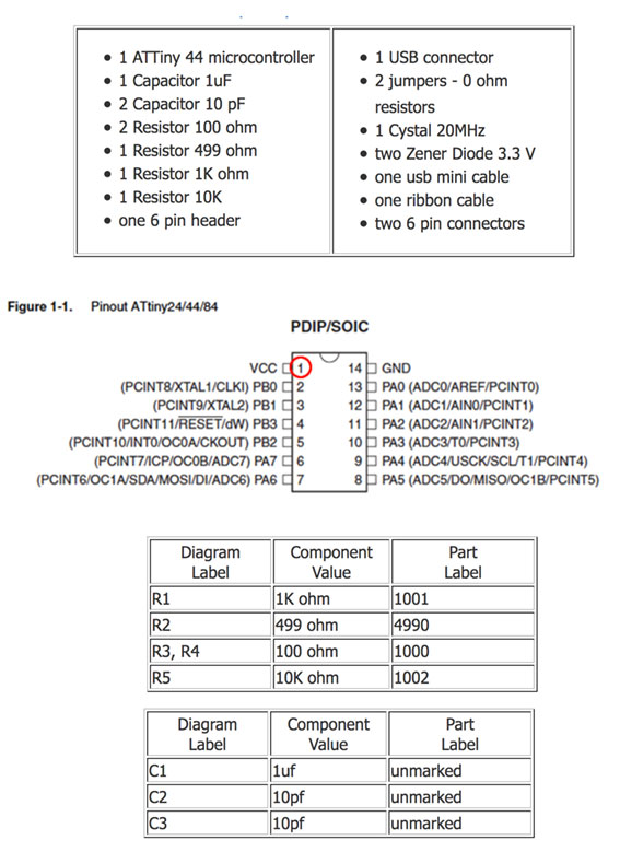
This is the aspect of the board at the end of the process and the electronic schema. It's like a map or guide to know where the components must be installed. You can recognize the elements on the right image and see the relations between the drawing and the reality.
We used also another helper, a table with all the components and their reference. But I'll talk about it later.
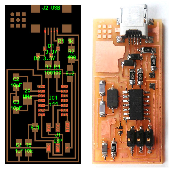
The first thing we had to do was downloading the original .PNG file. Milling machine is like a CNC, so it needs a reference. And in this case, the image file works fine; so I just took the model and got it a bit customized to recognise my board.
You can see perfectly the correspondence between this one and the one in the previous image with the electronic codes attached.
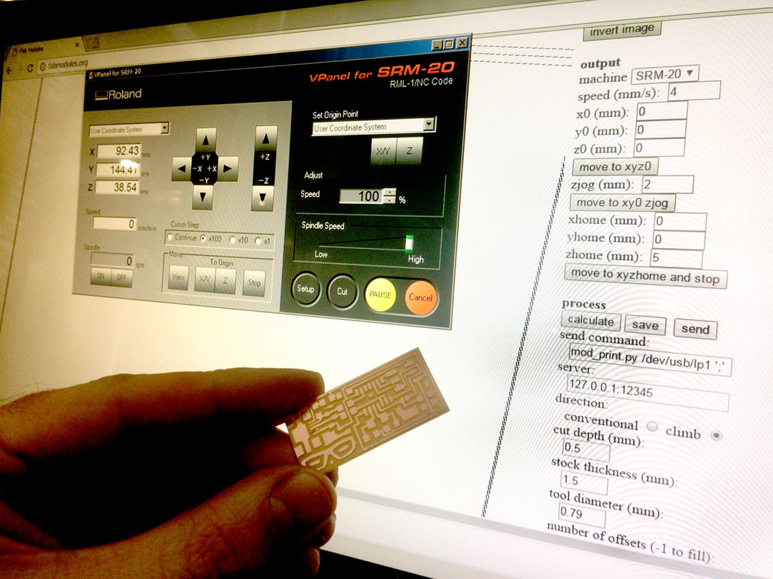
Next step is taking the design in the FabModules
That's the TOOL. It concentrates every single machine suitable to be used in the lab on a single interface. I's really usefull. But I assume that I'll talk much more about it in next assignments, so i'll stick to the present subject.
The first thing we have to consider is how are we going to cut our piece. We will avoid using small pieces, much harder to fix to the bed, and we will consider always to do our proces from the inside to the outside (the machine recalculates, but i'm talking about the concept and not the mechanism).
Introducing the levels for milling the traces is pretty easy, and the software shows you the path that the drill will follow and the direction of the moving head. Pretty awsome.
Things to check:
- Upload the picture and re-check the size, you will need to verify this in the cutting.
- Chose the machine in the output format.
- Decide which process you need. You'll see the options with the right drill besides. You'll have to change the tool for different process, of course.
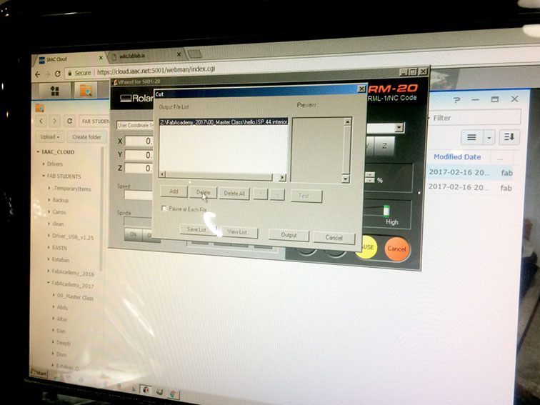
- Then you have to adjust the levels, ask for calculation (as you see in the image), and save in order to put in in the IAAC Cloud.
I used x0,y0,z0 with a 0 value. Then I used xhome and yhome value 0 and zhome value 5.
Cut depth 0.1 tool diameter 0.4 number of offsets 4 (you can fill the gaps using level -1)
and image threshold 0.5.
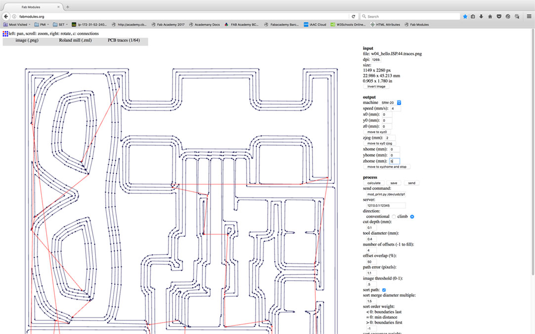
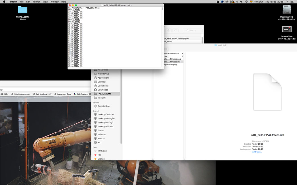
This is how the file generated by FabModules looks like... Pretty techy...
MILLING AND CUTTING THE BOARD.
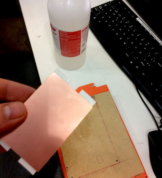
Next thing is the "real" thing. So we start preparing the bed. Wiping out any dust or irregularity in order the get a superflat surface. We used some alcohol to be sure.
Then we tape doble side scotch to the board, trying be generous, so we are sure that the piece of board wont move during the milling.
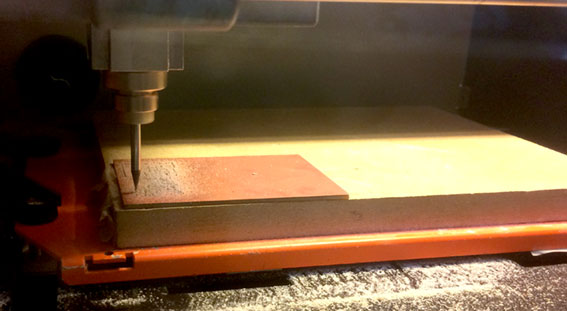
Then we take it on the interface from the machine. We adjust the 0 position, only in "XY" coordenates!! We set it, and the we start setting the "Z" first with the software and at the end by hand. The drill has to touch the layer of copper, and to be delicate we do it releasing the bolt while holding the drill.
Milling starts. First steps, we lower the speed to check that it's doing fine. Then we speed it up to 100%. This is the first milling process, the engraving.
You can see that we have a bigger piece of copper. That helps to get it more fixed to the wooden bed and saves time as three students could share the same board getting three individual pieces.
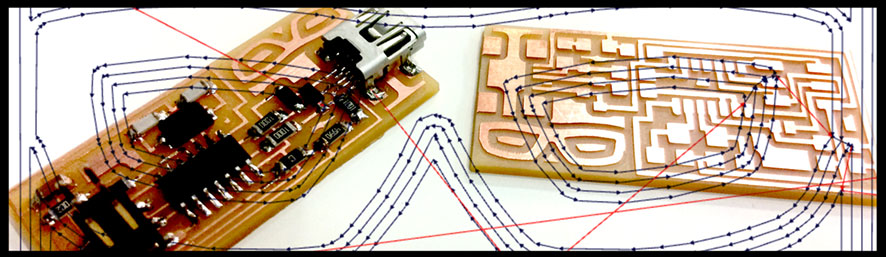
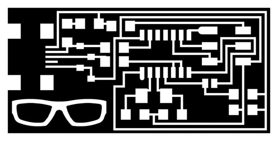
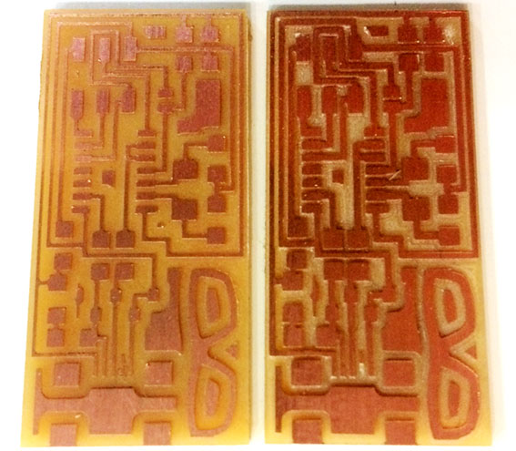
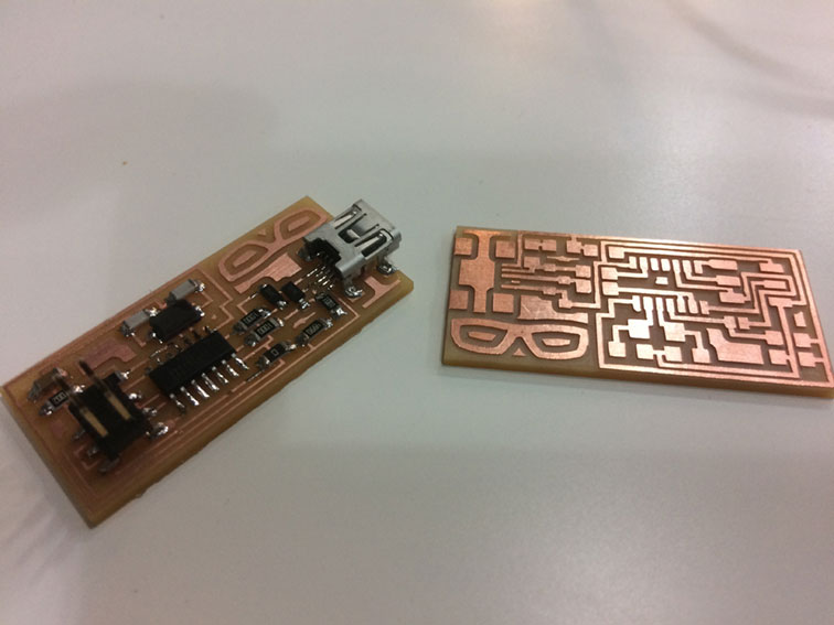
Well, that was the milling of the traces. But now we need to get our piece of board, the one we will use to solder all the components. So the process is very similar to the first image (that with the glasses) so I will be a bit more spartan on the explanations.
That's the image we are using to do it. Very important! Check that the sizes are correct. It will use the same "XY" coordinates origin. Wi will change de drill and the "Z", but the starting point is the same as the traces.
I used x0,y0,z0 with a 0 value. Then I used xhome and yhome value 0 and zhome value 5.
Cut depth 0.5 tool diameter 1.5 number of offsets 1. You see in the image slightly that the drill will pass three times, going a bit deeper each time, so we get our board cut at the end of the process.
I was not sure about the results. So I decided to mill a backup. I'm pretty sure something happened in the first one, because the second piece was much better. I'll try to do another test changing the offset. Maybe that was the reason.
The one on the right is the second one.
SOLDERING THE COMPONENTS.
First of all. Take the tools and get used to the thing. It's mandatory to get some practice before you start. It will save time, material and will keep your nerves on their natural position.
Maybe it's better to use a stand and a lens-lamp. But I managed to do it as you see. Well, up to you.
Best way to get your components! Write a list on paper and tape all the components. Open the drawer where the component is and leave it open, cut the component from the strip, and turn it back to the drawer and close it. It's better to know where did you take the things from.
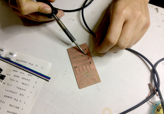
I unclude a very useful reference taht combined with the previous images of the circuit can help a lot. I'm not getting very much into this, because every circuit will have different configurations.
Most of the components we used have no polarity but DIODeS. Remember this in order to put them n the right direction.
OK! So final result and ready to check if it works.
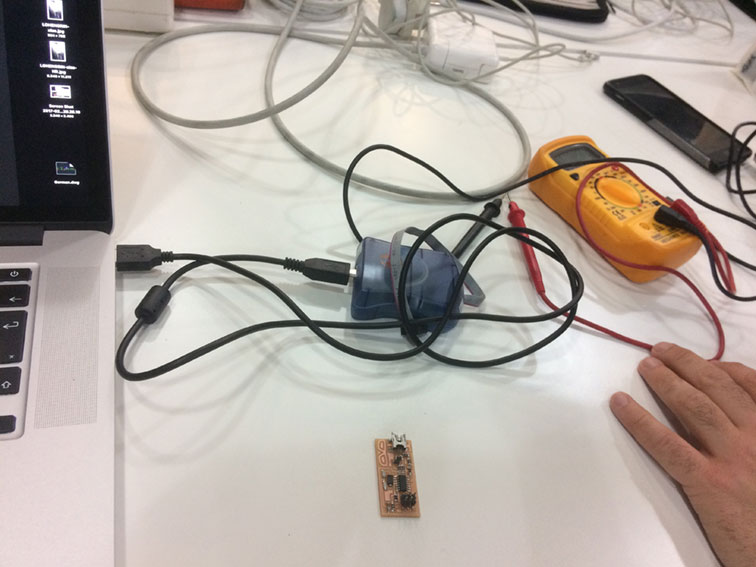
CHECKING DE FabISP AND PROGRAMMING.
I will need some more time to document this, because I wanted to understand more deeply what we are doing. I understood perfectly the workflow. But I think it dserves more atention.
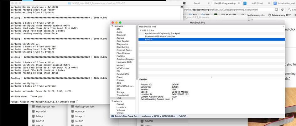
Still, some short explanations on the subject. First of all check that it works and the green light turns on.
First step, after installing the software, open the terminal and go to the fabISP fimware folder.
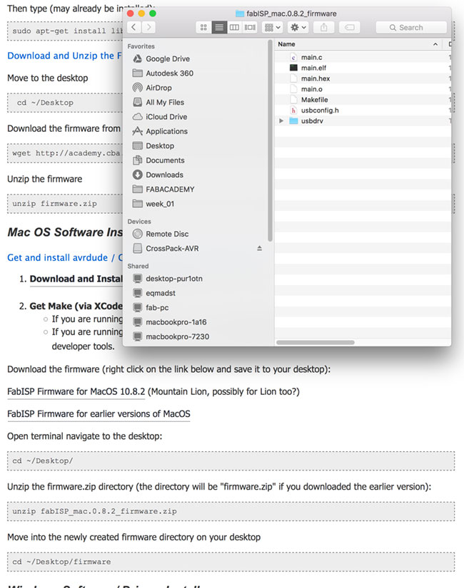
We need to be sure that there's no previous firmware, so we clean with the "make clean" instruction.
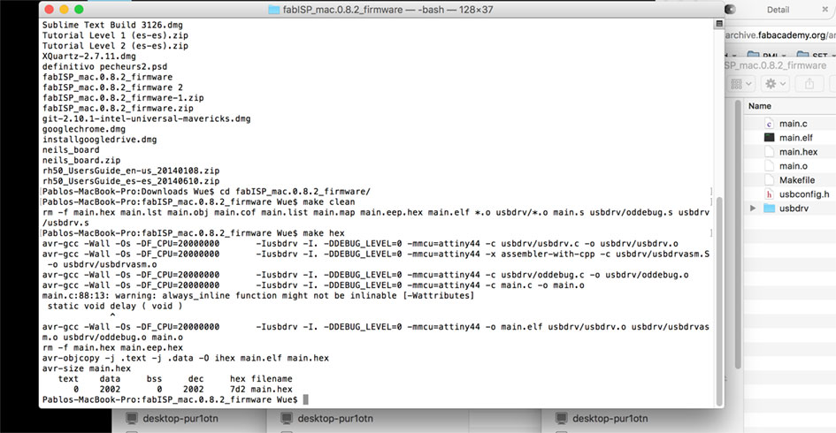
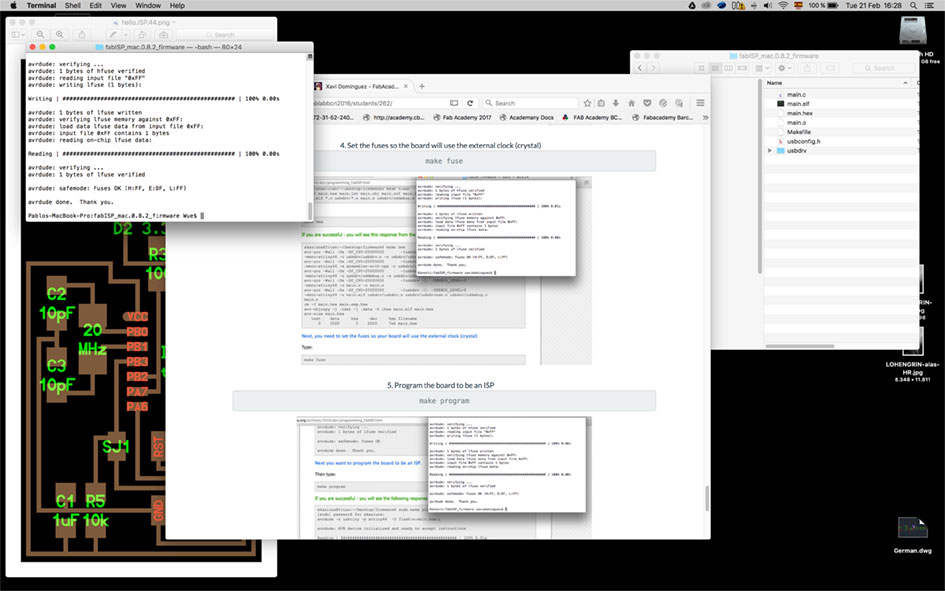
Then we convert the files into hex files with "make hex". And then, we do the same with "make fuse". That's the part I want to document more deeply.
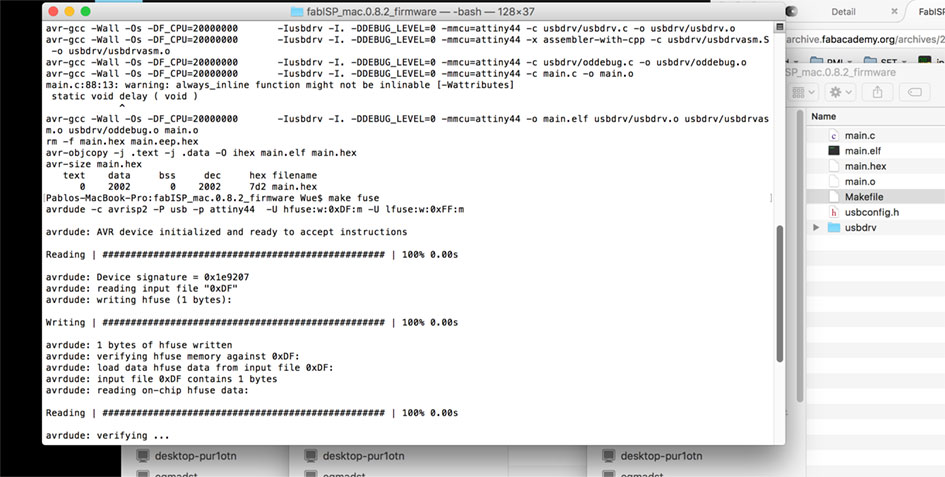
If everything works fine, the computer should be able to recognise the FabISP. So it did...
And as the final slide, I need to thank Xavi's tutorial on his archive. It was very helpfull and esay to follow.
Step by Step
- Check the tools, first impression.
- Understand the logics through practice.
- Do some tests with the technics you are not used to work.
- Be patient with the tiny things.
- Analyse the workflow and try to understand the abstract part of the electronics.
- Think twice what you're doing (get some backups!).
Method
In this assignment the method is clear. Use everything you can!