ASSIGNMENT 3.
Computer-controlled cutting.
Make lusercutter parts, varying settings and slot dimensions.
Cut something in the vinyl cutter.
Design, make and document a parametric press-fit construction kit.
GENERAL IDEAS TO START THE THING!
We start with one of the key resorces of the Academy (well, it's my impression, at least) and a VERY VERY interesting subject.
Cutting with machines is very similar to printing. There are many differences, though, and many details to document. In the assignment, I used a roland CAMM-1 vinyl cutter, the Spirit GE LaserPro, and the MultiCam 2000 laser.
All of them have different methods and displays, so the processes are slightly different. But the philosophy is very similar.
You have to keep some critical steps in mind, and tht's common to all of them, except to the vinyl cutter (there's no heat involved).
Let's start with vinyl cutting, and then we go for the laser machines... amazing week, indeed!
VINYL CUTTING PROCESS
Roland Camm-1We start with the machine understanding its parts and exploring the first steps to fit the settings.
The machine is very similar to a regulr small plotter. But instead of using ink pens, it uses a tiny turning blade. That's the firs thing we need to adjust. The nature of the prints we cut on this machine need a turning device, in order to flow over the material. This means thant the cutter can turn. Also important is to get the nice proportion of blade out of the moving head, so we don't cut the support layer of the vinyl sheet.
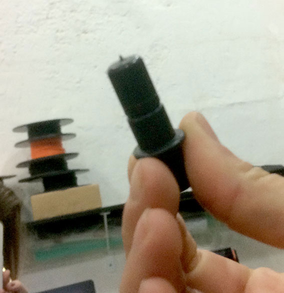
The first adjustment is visual. We do it turning the slider on the head clockwise or counterclockwise, depending on the thickness of the material we are going to cut. When you turn the piece you get more or less edge of the cutter. The range is not that wide. We have to consider that this cutter is not meant to cut thick materials, but meant to cut paper, vivyl, foil and thin stuff.
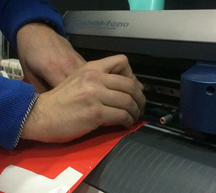
The we test manually the depth of the cut we get with the visible edge. It's important to have a clean line on the layer we are interested to cut, avoiding to go too far and affect the suport layer of the sheet. In case we cut both layers, we need to pull in a bit the blade by turning the small rolling slider.
Next step is to ask the machine to do a test by itself (we just need to hold the "TEST" button) and then check the settings we gave in the "command" console. This is a simple machine, so the commands are easy to understand, and the buttons are simple as well, so remember to press for a while to do the test cut.
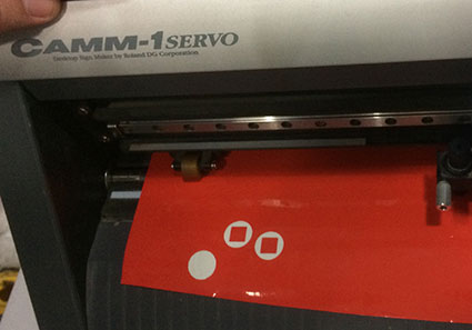
The objective is to cut a circle with an inner square. We have to do it in a way that we can pull the cookie between the two shapes without dividing the support layer. That means we managed to cut just the vinyl.
Then we start defining the file we want to cut. In my case i used a contrasted photo, as a kind of stencil, so it's esay to raster and maintain the logic of the motive.
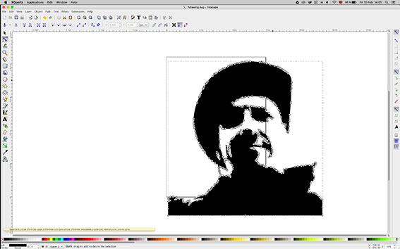
I used Inkscape to raster the image and to scale it. I used diferent settings to do it in diferent copies of the motive. It's important to consider the "noise" we get from ratering a low definition image and the tricks we can use to reduce it. We did it with some letters, that are much more critical in terms of edge-noise issues. The result of my tests was very similar. Maybe using more extreme grayscales between the copies would give a more illustrative result on this test.
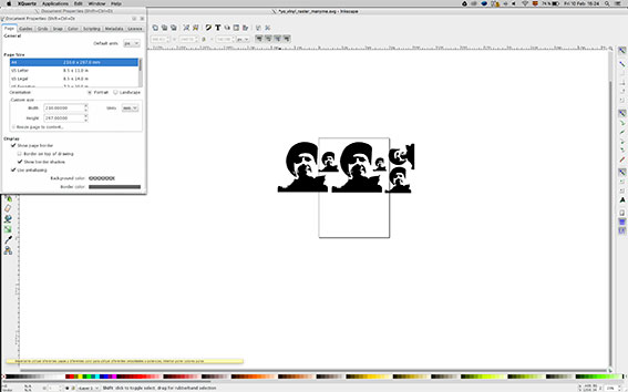
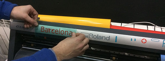
So far, i just copied the motive in diferent sizes and settings from the original. But control points where not varying that much. Some early tests were made with fonts, as I explained, and in that case, we could see the difference. TIP: using fonts, you would raster with a big size and the scale down the motive. The dust in the edges gets very reduced this way. You can see it in the "barcelona" logo on the header image
Also important, when you export the file, check the page dimension to include all the motives you plan to cut, and use AI versión 8. That was a recurrent need for the whole group of students.
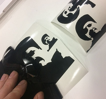
Once your motives are ready cut, remove carefully the areas you're not interested in by pulling carefully in a flat direction, parallel to the vinyl. You may nedd some tools to help, depending on your motive.
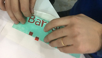
A transfer layer is needed to get your shapes on a handy "sticker" so you will have a new support that will keep your stuff as you planned. This way you can easily place it where you want.
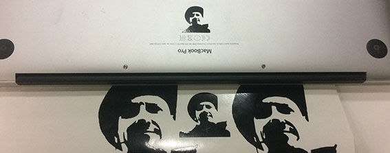
Voilá! A small one for the laptop and keep the rest without the transfer layer! I used a roll, therefore I didn't want to waste material and I got 5/6 stickers, different sizes.
You may use only a piece of vinyl; in that case, the settings on the dimensions should be considered more deeply, but the machine have some automatic recognition devices. It's just a question of reviewing the manual.
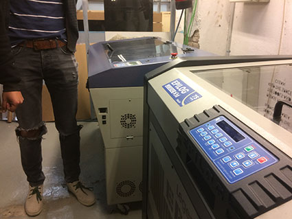
LASER CUTTING PROCESS
MultiCam 2000LaserPro Spirit GE
All the laser cutting machines have a similar way of working. Of course they have different features depending on the power they cut with, the speed and the mechanical system or the adjustments workflow.
If I have to describe the key features you HAVE to check ALWAYS, I would remark this ones:
- The adjustment of the distance is critical and it's something you aways have to check. Most of the machines have a similar workflow, but keep in mind the thing, because some of them are not automatic and doesn't have a self-integrated sensor.
- The ventilation system is very important and you have to be sure that you are working with the correct safety standars. Check that it's working
- You always have to make a test, even if you have the levels on a paper. It's not that boring and you will remember the previous steps when you test your cut.
- The three critical levels are the frequence, the speed and the power. The combination of this three values will providi you with a nice looking collection of pieces or with a burned piece of material and I maybe some disapointing surprise.
- I recommend to read the manual, always.
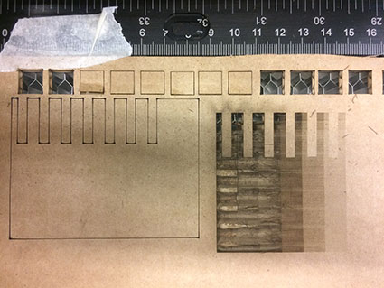
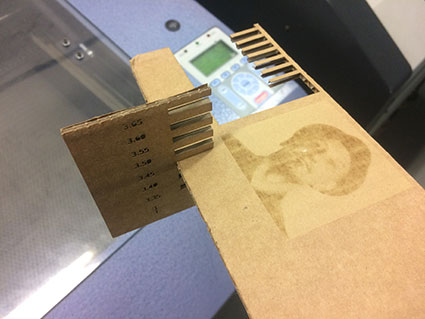
We got a quick an useful explanation, and some detailed tutorials with the machines. But first I started designing the piece. A reference board with several thicknesses combined with grayscale levels to have a 3 in 1, so I could try both the cutting, the engraving and the rastering.
I did many tests, nd some of them kind of worked as an experiment. But the results were just illustrative, not ideal, so I decided to split the lines of investigation, in order the clear a bit the items independently..
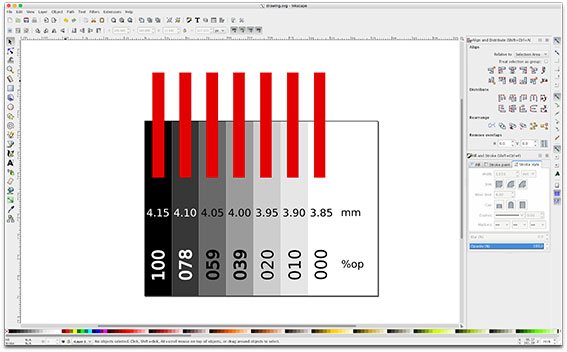
I started to draw with Inkscape. I wanted to have a single design to cover the three branches of the experience. So I added a grayscale marked with numbers identifying each value, and the slots for testing the thickness.
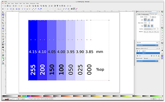
It was not clear for me how to deal with colors and layers on the machines, so I prepared several versions of the same file. It turned out as a failed experiment, but it was quite interesting to arrive to the conclusions I will explain later.
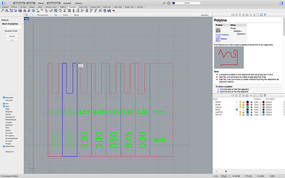
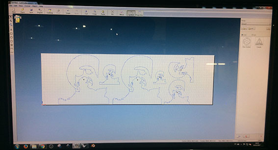
Just in case it didn't work with Inkscape, I made the same file in Rhino, but since the nature of both programmes is a bit different, I had to redraw the lines based on the inkscape reference.
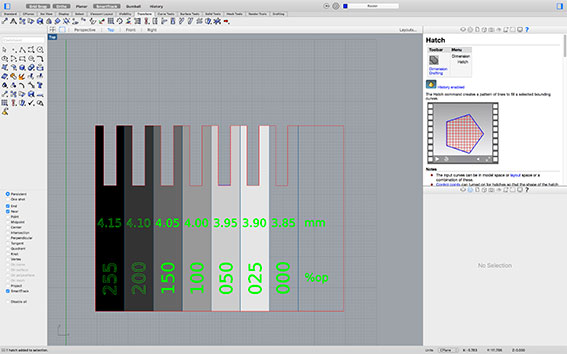
I used the "hatch" in Rhino with diferent leves to get this gradient, following the colour code of the laser cutting machine. But later I had to reorganise some of the elements to get a nice result. It's not clear yet who rules, wether the colour of the element or the colour of the layer.
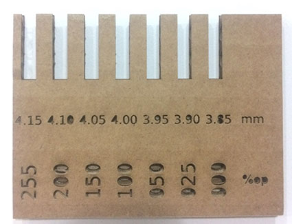
These were the results with my first settings. Working in the machine was a bit slow, because the result is the result of combinations of three diferent values. It took sometime to understand the consequences of increasing or decreasing any of them, also because I was misunderstanding the colour code of the layers, I guess. Still, we made a test.
As you can see, we worked in samples until we found some values suitable for cutting. But the raster didn't work well. I guess it´s a question of density of dots. And so far, i guess it's kind of complex to work with raster in cardboard due to the concentration of heat on very dense dot patterns. Of course, if you decrease the power, you get better results on darker colours, but then you loose the bright ones. I decided then to skip the raster experiment and to open an extra chapter focused on that subject.
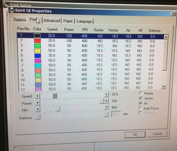
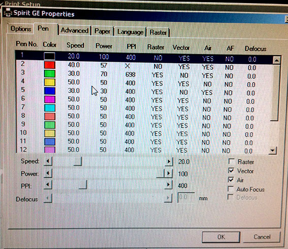
At the end we arrived to this conclusion. Here are the values that we used. I say "used" because they worked well also for the rest of the students. We used them extensiveley and the resut were ok, also in the engraving with bright colours. Pretty cool tests. I don't know about the raster, because even if I saw some of them, I don't know what the adjustments were.
In the previous image you can see the adjustments of cutting. I was using the red layer, and changed that levels. But at the end, I decided to adjust both the black (normally selected for cutting) and red to the same levels. And it worked perfectly.
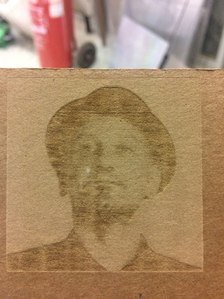
The chapter on raster was kind of short, but I want to take back on it. Basically I decreased the levels of power to low levels, so I could have a first impression and work over this first version in the future. To my surprise, the resut was not bad, so I decided to give priority to the third assignment. It was a simple adjustment on the power and once it's documented, I can recover it easily.
Final result of the assignment. I didn't focused the present documentation on the instructions manual of the machines, since they have diferent ways of doing the things and the manuals are available. The documentation is actually for one's own purposes on design and tranquility on the use of the machines. Here I wanted to focused more into the experience, not in the "mechanics".
PARAMETRIC AND PRESS-FIT CONSTRUCTION MODEL
Fusion360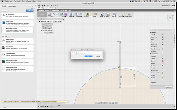
For the parametric assignment I used Fusion360.
I wanted to investigate a bit the software and I'm expecting a nice feedback concerning version control capabilities of the software. Let's see. I'll get back on it as soon as I need to develope the project in "real world"
I started a sketch defining the shape and the measures.
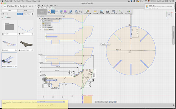
I added the two pieces of the model in the same sketch to lose no time in the assemblies aspects. That deserves a diferent chapter.
I started figuring out which measures should be linked in orther to organize the collection of parametric values.
I considered the thickness of the material, the deep of the slots, the number of inserts and the repetitions of the "branches".
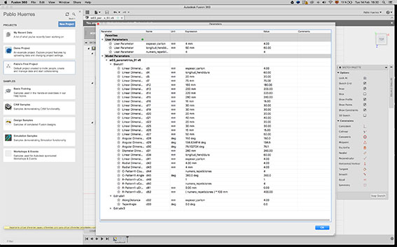
Here you see the collection of measures involved on the sketch and the parametric values defined by the user.
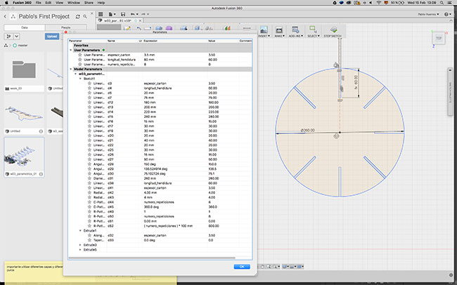
First image to check the functions of the parametric values...
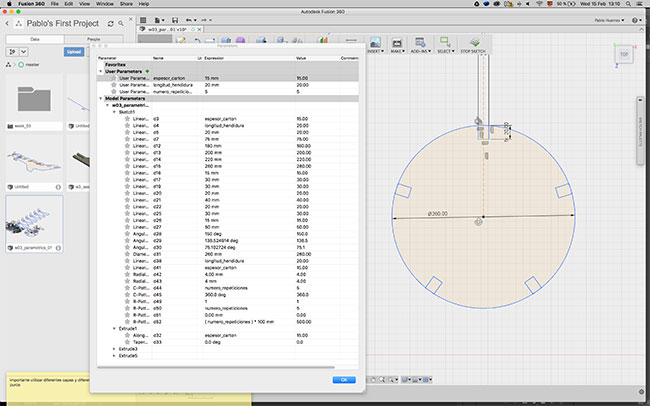
Second image to check the functions of the parametric values...They worked!
First image to check the functions of the parametric values linked with repetitions...
Second image to check the functions of the parametric values linked with repetitions... Also working!
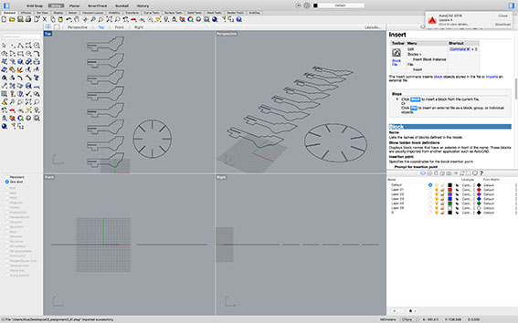
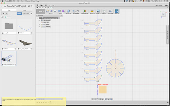
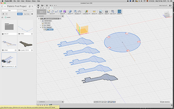
Exporting to Rhino to relocate the pieces in order to minimize empty areas and avoid wasting material.
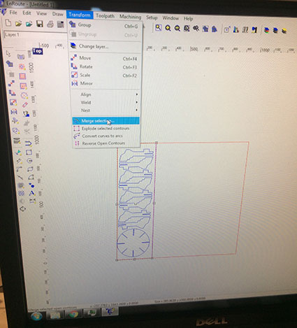
The whole process of engaging the machine is something that I have to document in a diferent chapter. Same considerations for all of them. They're different and they need specific tutorials...:)
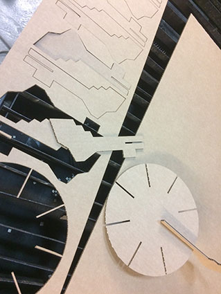
Final pieces already cut........ and time to check the press-fit assembly. Working fine with 3.5 cardboard and long inserts. I have to develope the constraints of some parameter to avoid posible colisions if the user doesn't remember the limits (or just find the way to limit the range of the parameters)
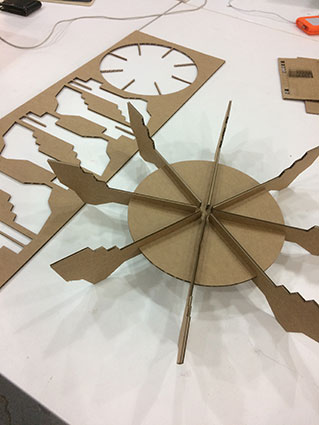
The prototype already assembled. Then I realized that some extra parameters were needed (and some measurements in real world as well)
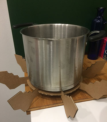
Final result. Not working on casseroles, but expected to work fairly well as a rack for paellas (big size ones!)
First conclusions
- It's a question of time to improve. But it's very fast to check the improvements when you work with laser cutting machines.
- You have to understand what you need to do in order to chose, and measure it first man!!
- I'm in love with this assignment!!