Exercise 11 & 13
Input Device & Output devices
Microcontroller ATtiny 44
"Brain" of the board. Will controll the input and output of connected sensors and output devices. Is able to connect to other processor with the optional bluetooth controller.
2 x 10kΩ Resistor
One of the two 10kΩ resistor is in series with the photoresistor and prevents it from being exposed to too much current. The other 10kΩ resistor is necessry for the reset pin when programming the board.
1 x 200Ω Resistor
The 200Ω resistor is in series with the led and prevents it from being exposed to too much current which would damage or destroy the LED. 1 x 1µF Capacitor
The capacitor evens out the incomming current signal which might be necessary for fluctuating power sources.
Pin Header
The Pin Headers provide a possibility to connect external devices to the microcontroller. This board has pin headers for.
Bluetooth Module (VCC, GND, RX, TX)
provides a possibilty for a bluetooth connection to the microcontroller via serial communication (RX, TX)
Non SMD Photo Resistor (VCC, GND)
A photo resistor changes it's resistance based on the amount of light it is exposed to.
Servo Motorcontroller (VCC, GND, SIGNAL)
A motor is an external device which converts current to rotary movement.
Programming (MISO, MOSI, SCK, RESET, VCC, GND)
Those are the pins necessary for programming the board.
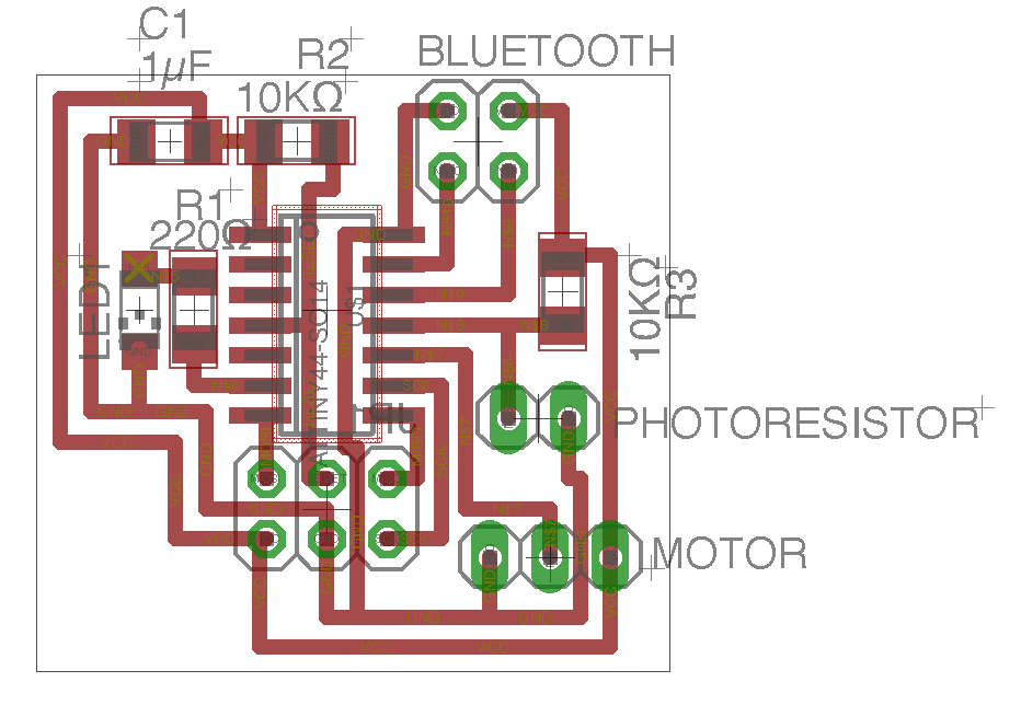
Circuit board
I design this circuit board on exercise 8.
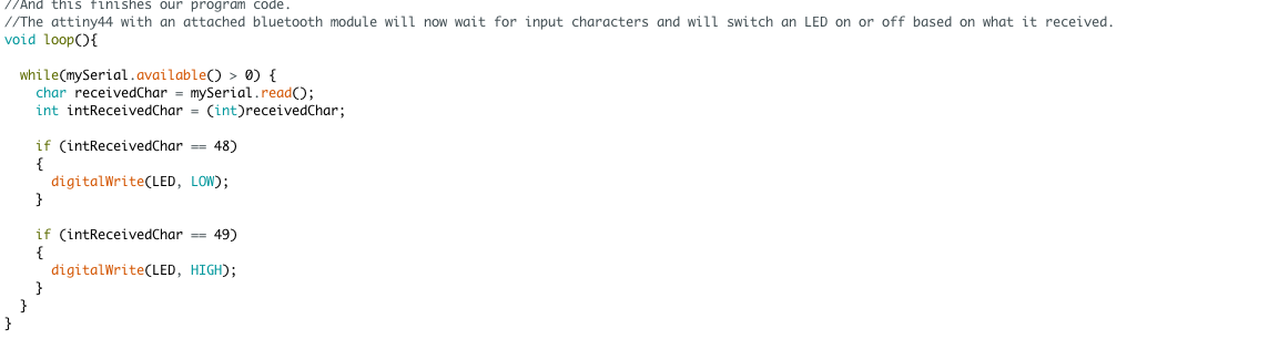
Input & Output
The following is blink code.