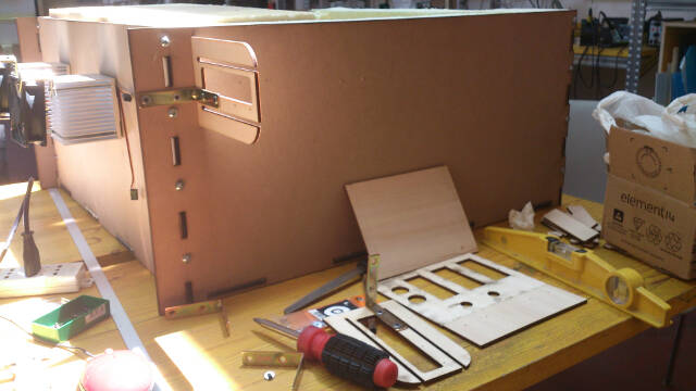
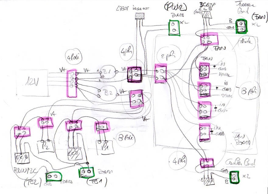
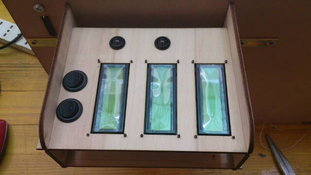
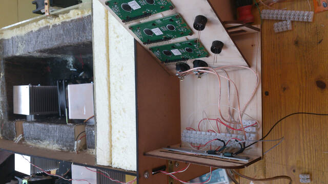
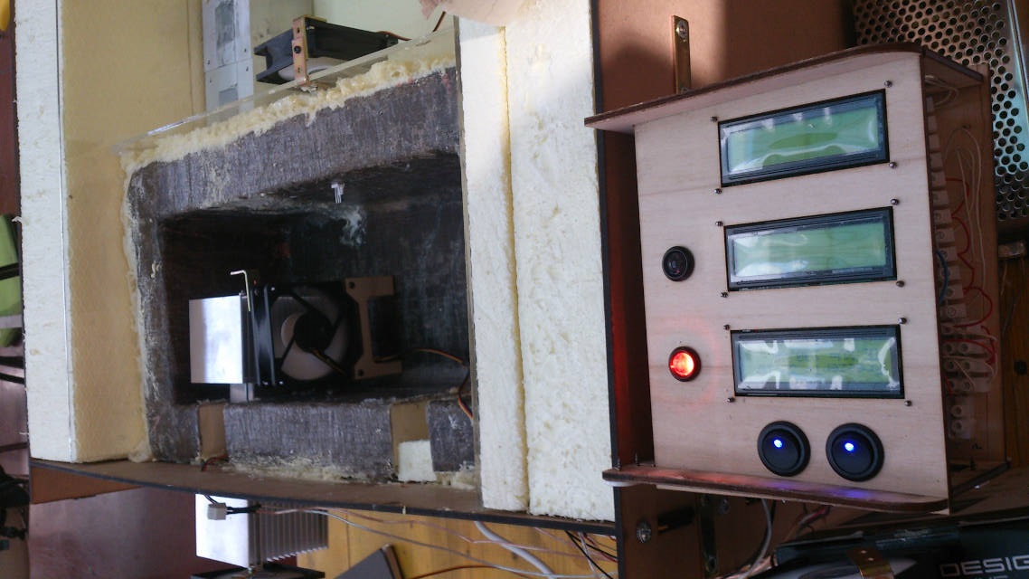
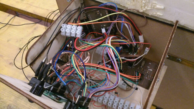
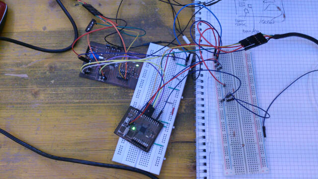
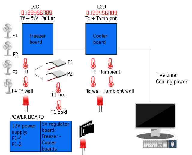
This image summarizes the project electronics which will transform the assembly in a real test bench to investigate product optimization:
Two boards with LCDs;
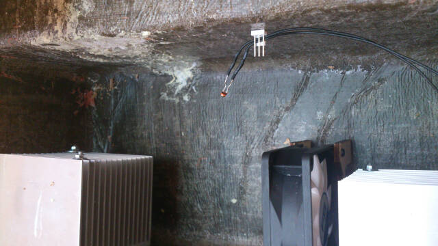
Two thermal groups with Peltier elements
Four fans
Eight temperatures sensors
On-off switches with warning lights
Connections between boards and PC
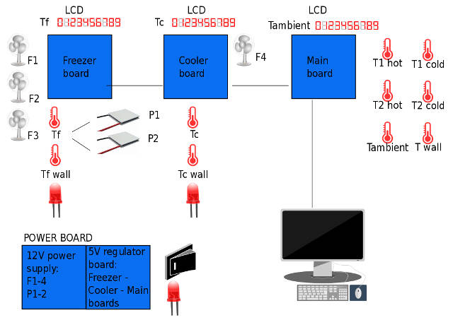
To be honest, I had initially imagined three boards but, to keep the schedule of the project, and to avoid excessive complication (I'm an engineer ...) I simplified the scheme.
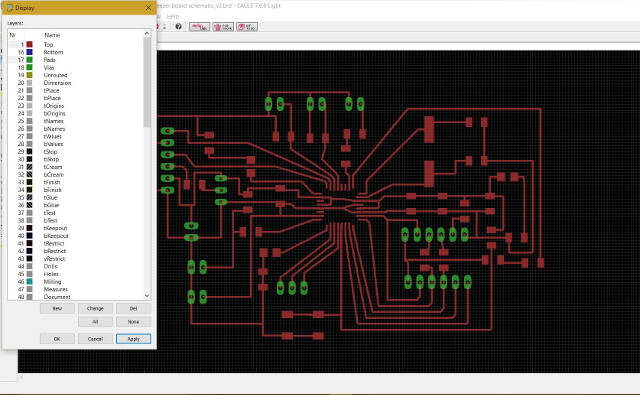
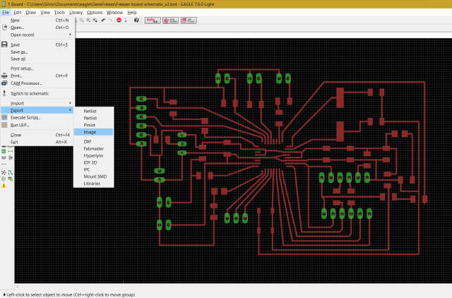
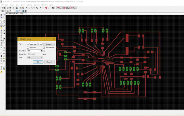
PCBs design and production
Link to weekly assignement
The process of making the boards links directly with the Input / Output devices assignements. In fact, the boards comprise everything that is needed to link to sensors, peltiers LCDs and fans. Moreover, they make avalaible the microcontroller pins necessary for networking and communication with PC.
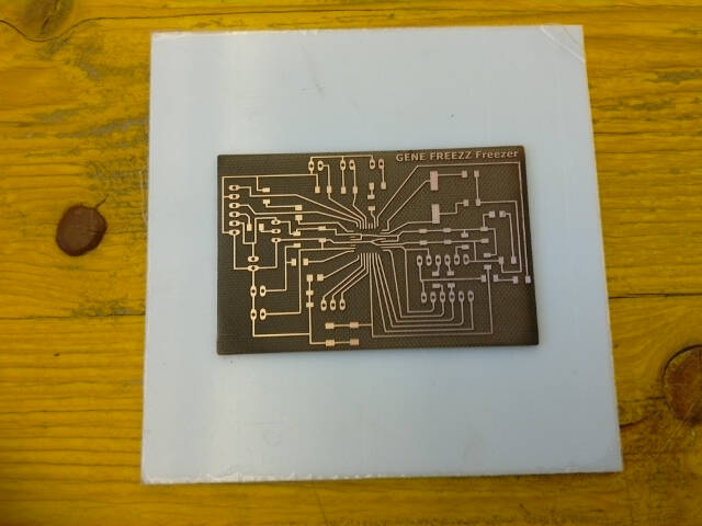
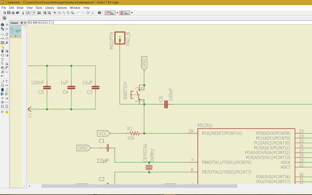
Since I opted for the Arduino IDE, I took inspiration for the boards from the Satshakit. One of the boards, the Freezer Board. I designed it from scratch while for the second board, which I named Cooler Board, I used a Satsha kit I made during the electronics assignements, integrated with an additional board which carries electronics components missing from the Satshakit.
The genesis of the different boards comes from analyzing and understanding input and output devices. We will therefore link to the relevant assignements:
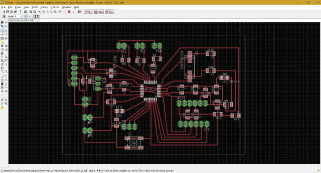
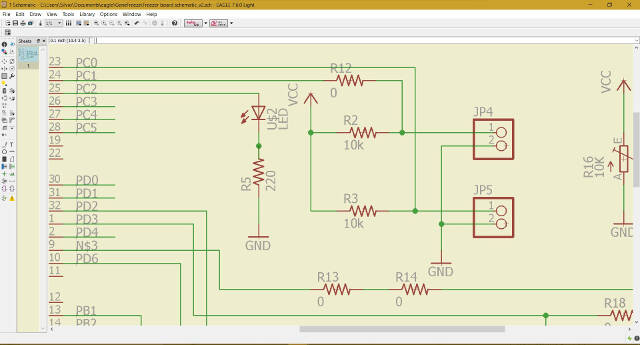
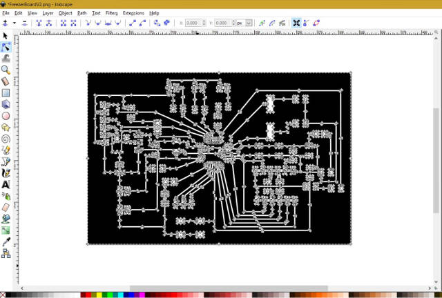
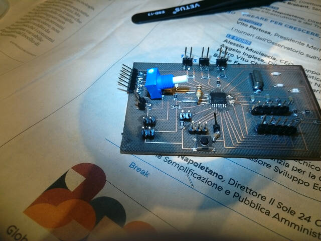
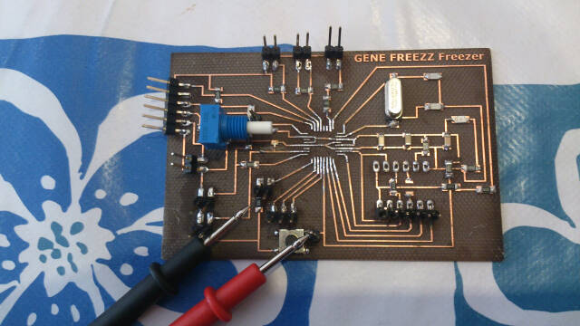
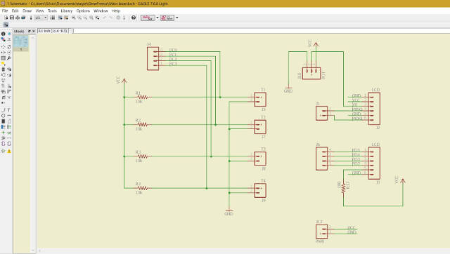
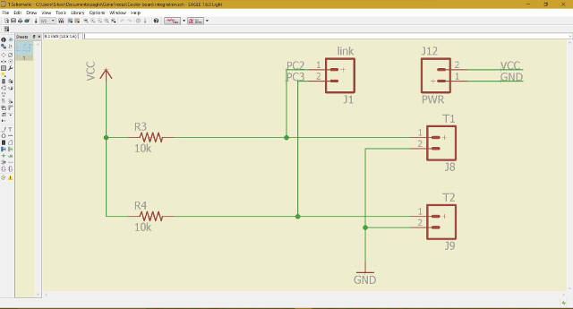
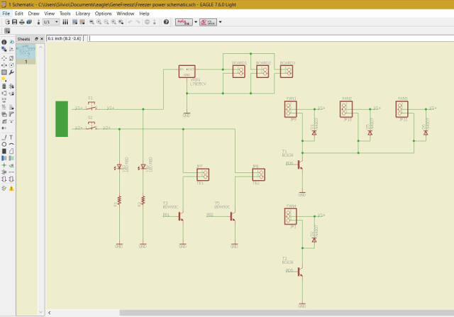
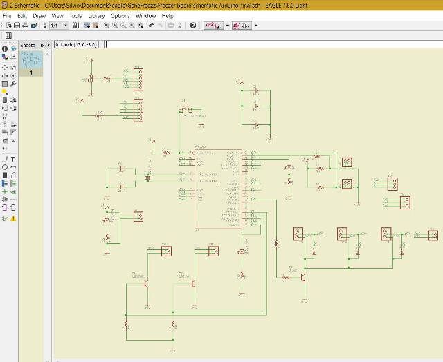
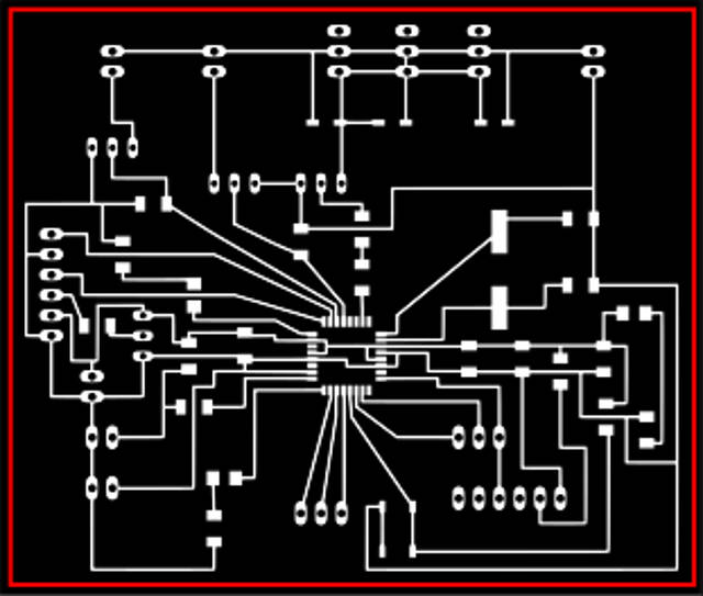
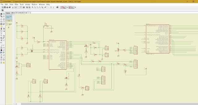
This is the first version of the board which includes control of the different input and output devices
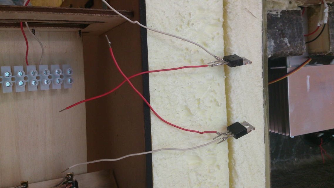
Here I correct the pin sequence of the Peltier transistor
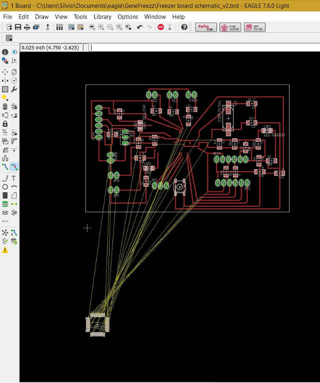
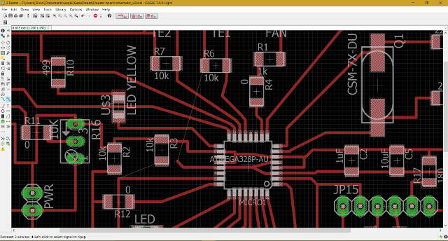
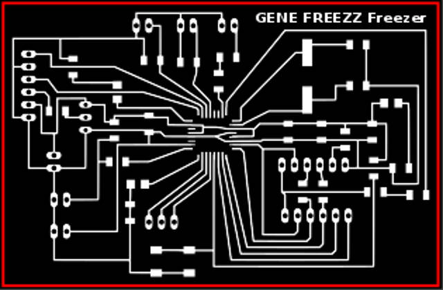
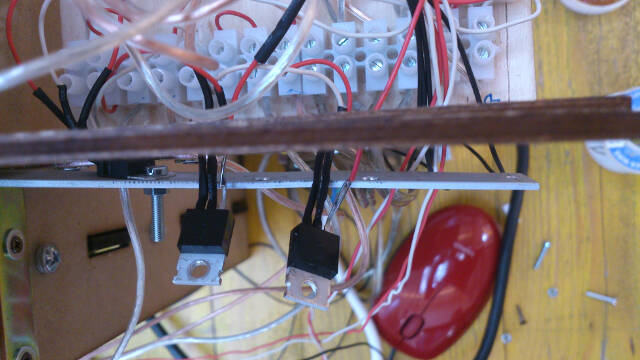
In the second version of the board I moved out all the power wiring. In fact, the Peltier elemnts drive currents between 2 and 3 amps which I thought more suitable be driven on a separate "board", the wiring of the power cabinet which collects all power connections (12v)
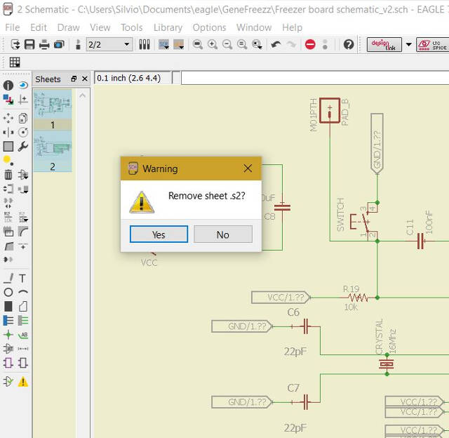
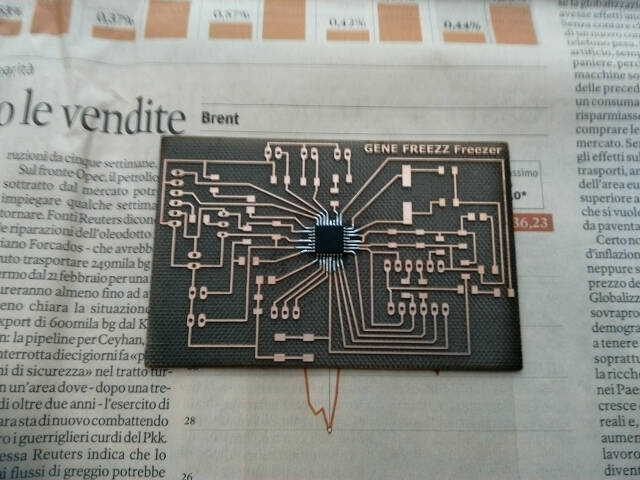
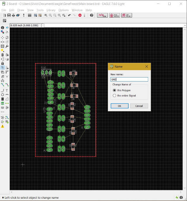
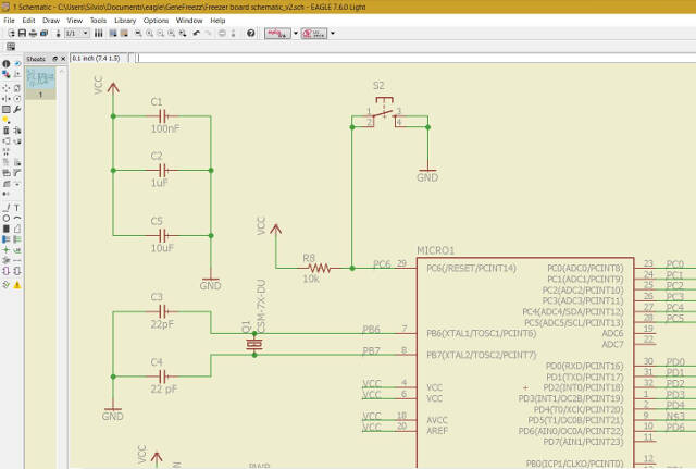
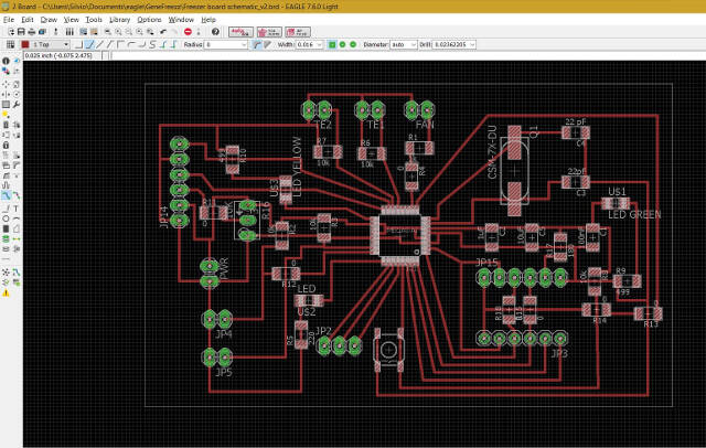
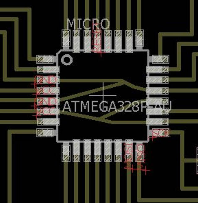
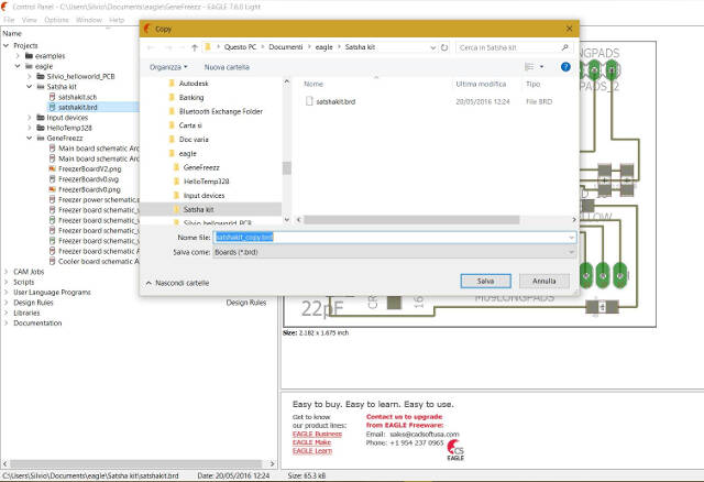
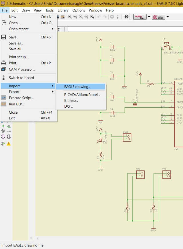
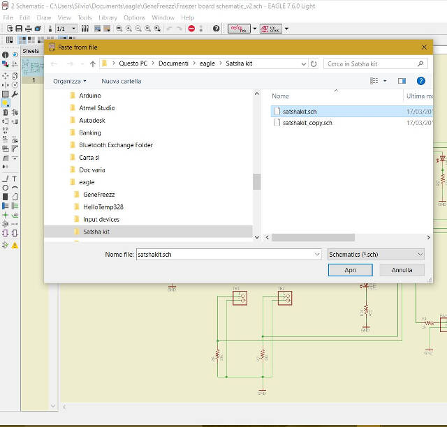
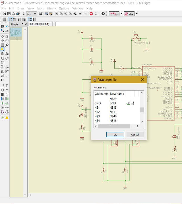
I then decide to change in the Eagle schematic the part representing the ATMega328 microcontroller with a version with more space between pins. I chose the one used for the original schematic of the Satshakit. In this way I also tested the possibility of coèying and pasting parts, or group of parts, between differnet schematics
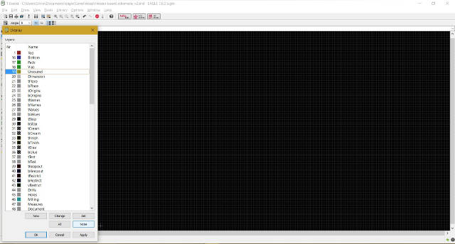
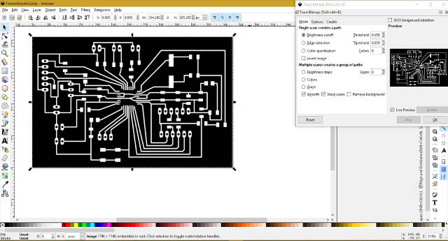
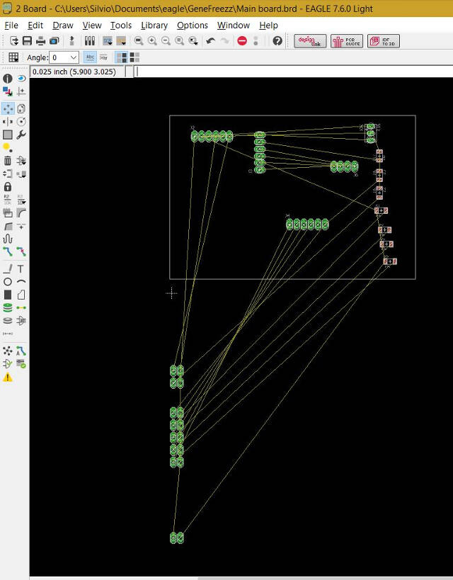
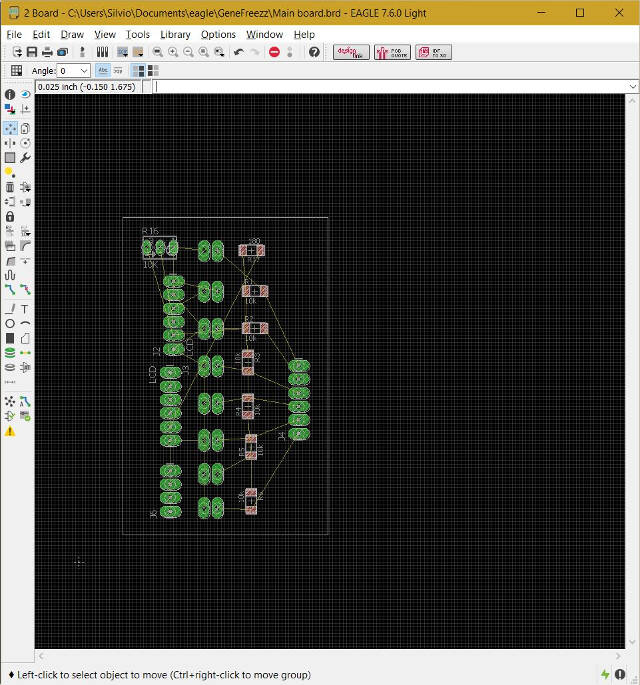
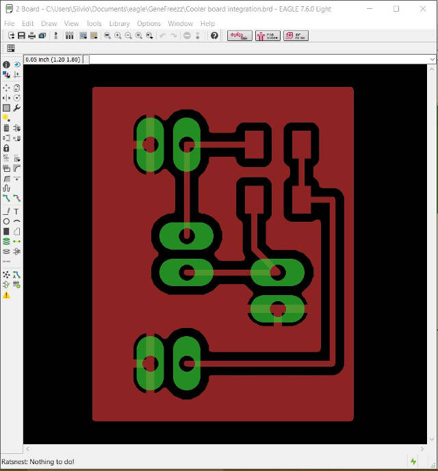
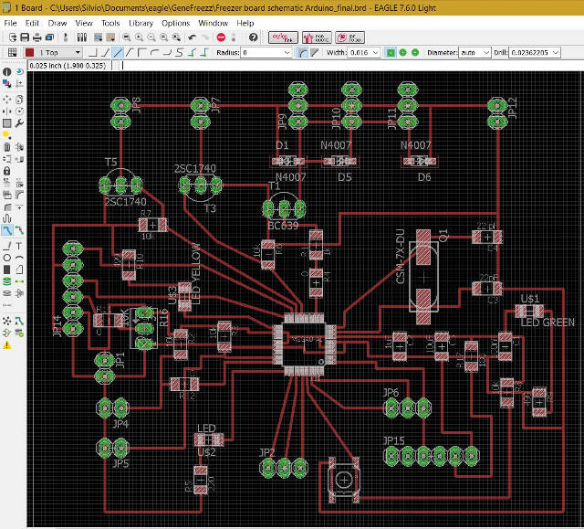
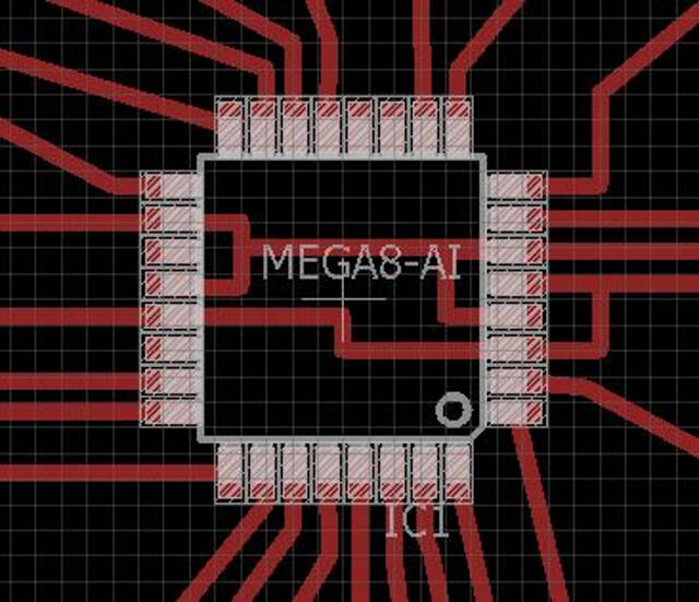
Checking no unrouted paths were left out
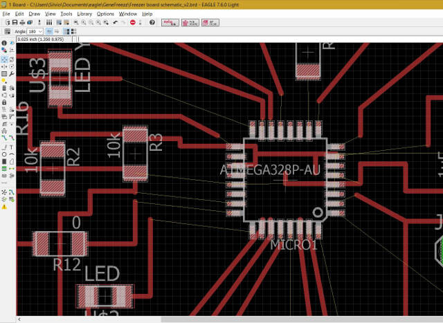
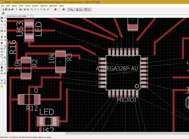
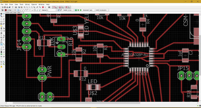
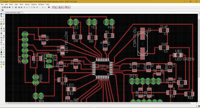
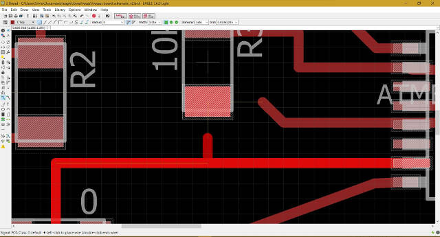
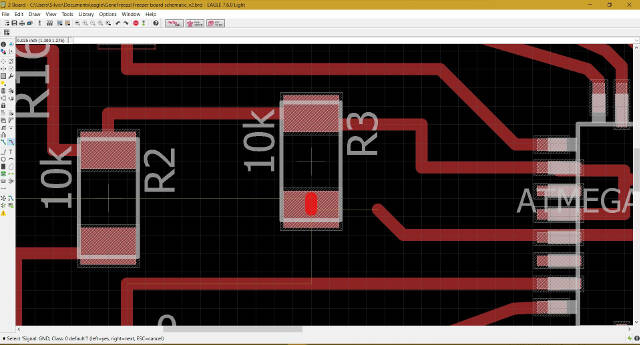
Even though I had amde all the check on the board layout a component, a resitor, remained connected to both ground and power. It took me a while to find the error that was not highlightes by Eagle. In fact, a piece of connection was hided by the component and created the short circuit I coul not explain
Here we see the routing before and after the issue was solved
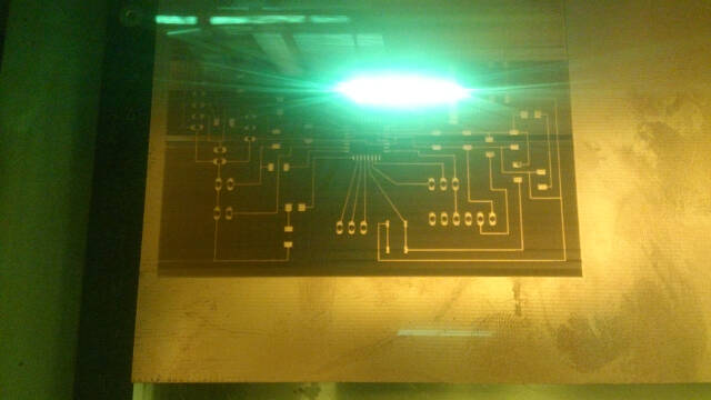
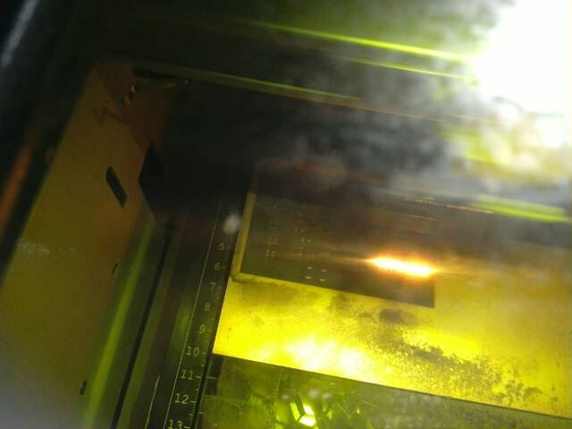
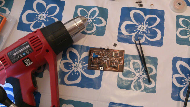
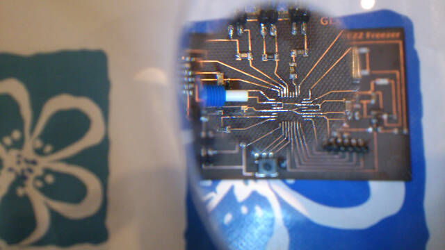
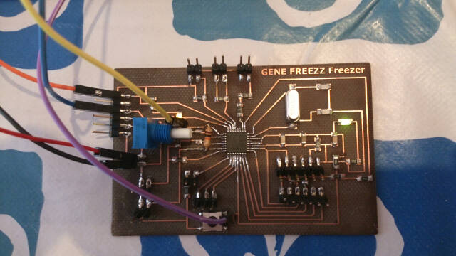
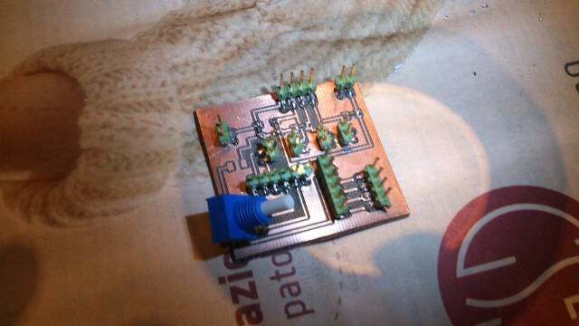
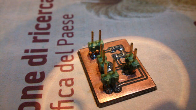
Freezer Board production
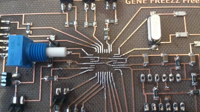
Freezer Board Solder
Several times, during the Academy, I came across the board "signature" issues related to using the Arduino IDE. I detail this problem in the coding section. In any case, this, having soldered the microcontroller ALMega328 PB, whic I did not now is not compatible with Arduino, I had to desolder it and replace it with a compatible model (this is a limit of the Arduino solution ...).
Surely I learned how to solder and control the microcontroller.
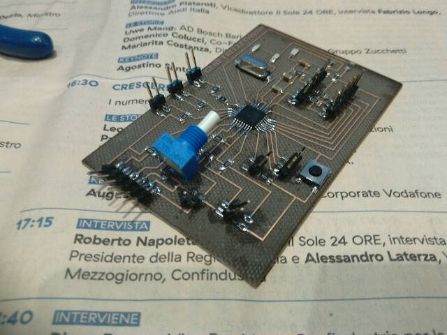
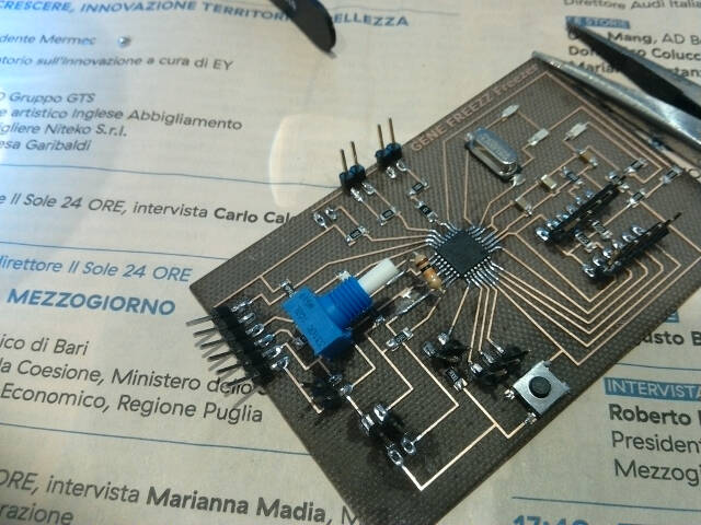
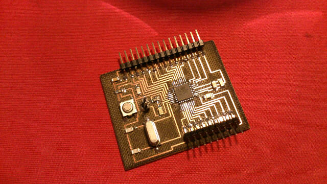
Final board
Satshakit Board
Cooler Board
The cooler board works in connection with the Satshakit, integrating components to control:
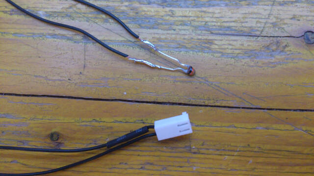
#4 thermistors;
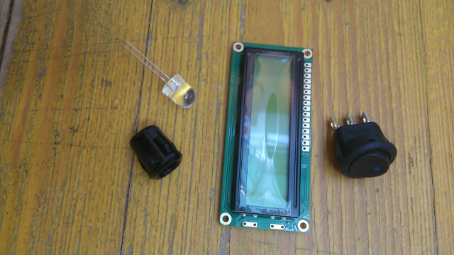
LCD with potentiometer
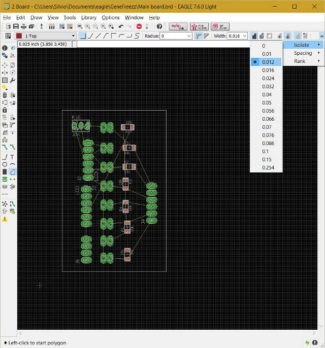
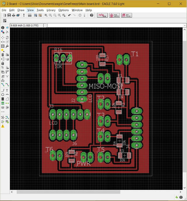
In this case, I added the copper pour for the ground signal
Other integrations
I made another integration board for the freezer board adding the possibility to manage two additional thermistors, for a toal of four.
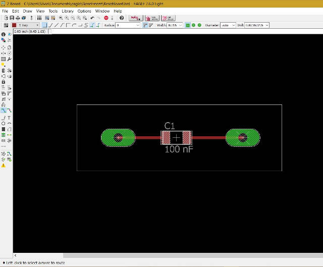
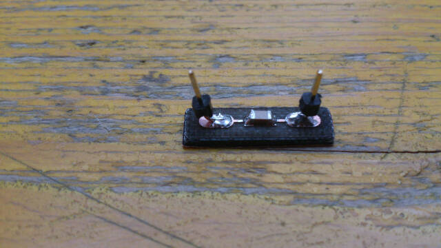
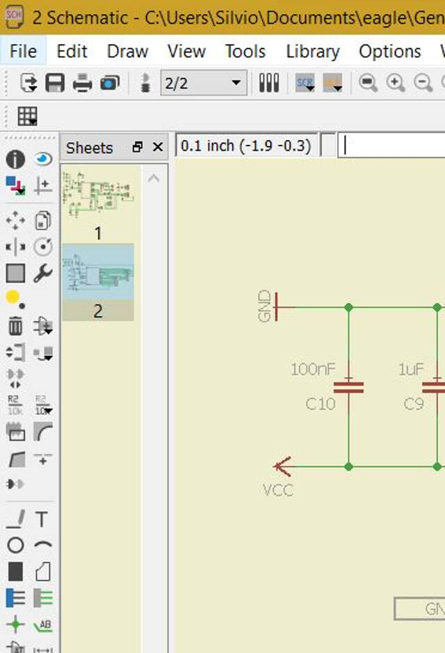
And a second integration covers the SCK pin with the 100nF capacitor I forgot to include as in the official Satshakit board. This integration is necessary when connecting the board to the serial TTL-232R cable.
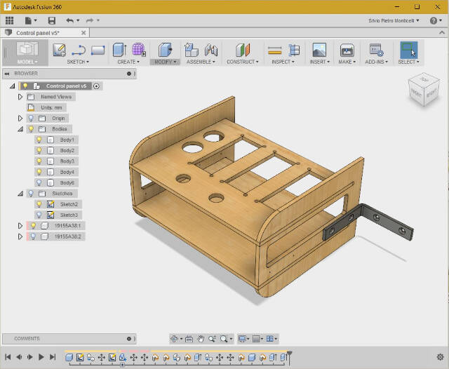
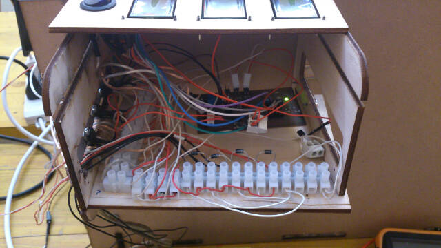
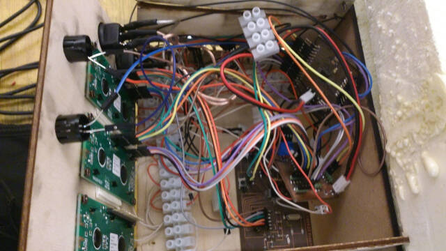
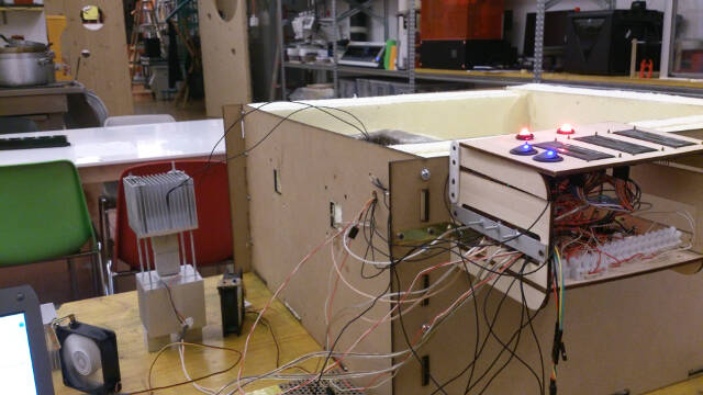
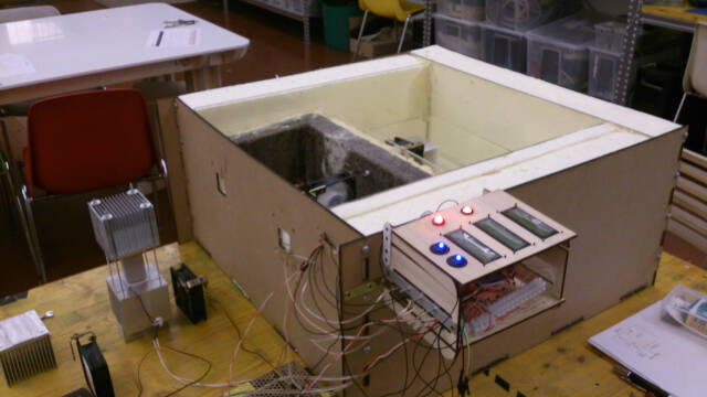
In order to wire the cabinet I would have needed a wiring diagram where you find the physical location of the different components. To match the project timing, I resolved to a manual drawing which, though a bit messy, gave me a better perpective of the wires path.
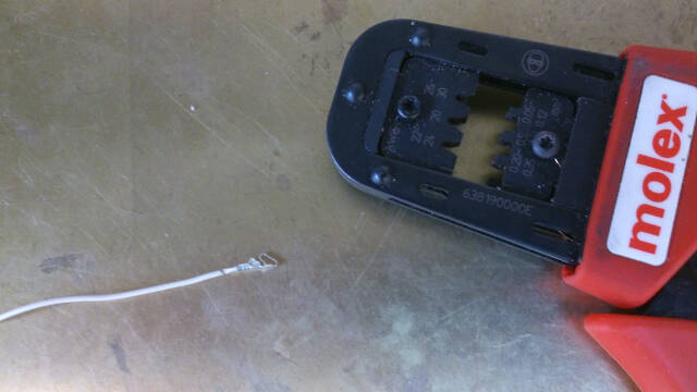
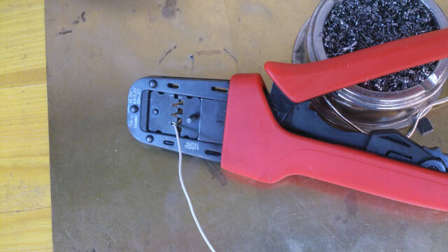
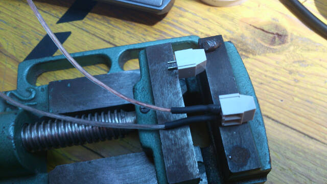
Actually, I should have made a bigger cabinet. Wires occupy spavce exponentially and squeezing in the boards, connectors, transitors, etc. becomes a real challenge. Also, preparing the cables terminations is surprisingly time consuming.
Nevertheless I made it to finish the job.
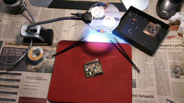
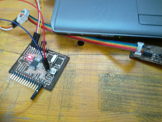
This section covers the activites I made to upload the sketches to the two boards I made in view of testing the overall system
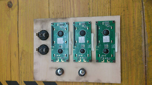
Once the code uploaded, prior to inserting the board in the control cabinet, I made different tests using a breadboard and through hole package components
Here's an important issue I already mentioned in the above Freezer Board Solder section. The microcontroller signature.
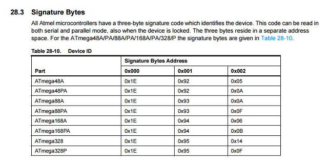
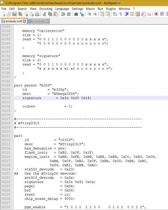
Every type of microcontroller has its unique signature as shown in this extract of the ATmega328 datasheet
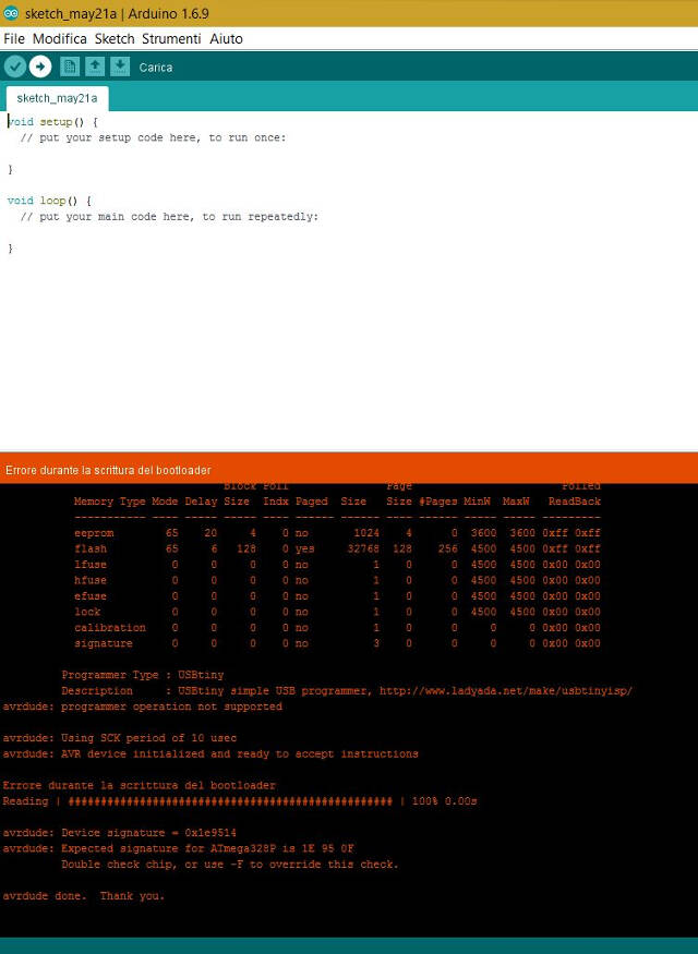
In short, when you send the bootloader to a microcontroller, the signature must be the right one, otherwise the uploading process aborts. Similarly, if you send a sketch to a microcontroller.
What happens is that the avrdude file involved in the toolchain process enquires the microcontroller for the signature.
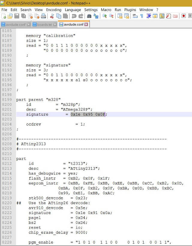
Ity took me a while to understand what to do but at the end the solution is starighforward: modify the averdude file with the signaure you need. The avrdude.conf file is located in the following repository (Windows): C:\Program Files (x86)\Arduino\hardware\tools\avr\etc.
For example, the ATmega328P used on the Arduino boards has the siganture 1e950f while the ATmega 328AU which I used for my boards has the siganture 1e9514.
Beware that the new Atmega 328PB series not only has a different signature, but it is not yet compatible with Arduino!
Certainly, this is a limitation of the Arduino environemt, which, in order to standardize, brings in some limitations.
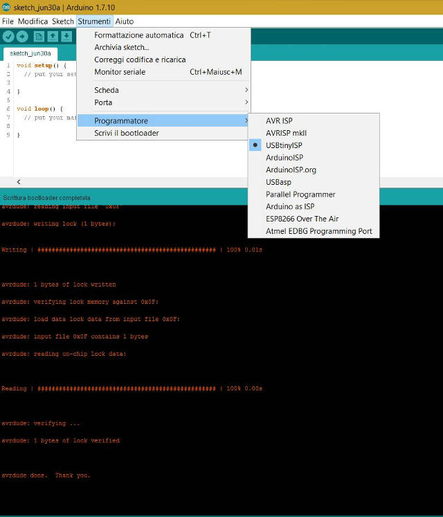
Bootloading via FabISP
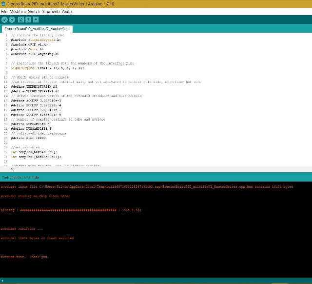
Uploading the Master code to the freezer board
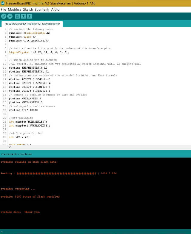
Uploading the Slave code to the Satshakit/Cooler board
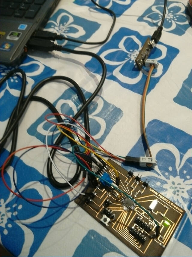
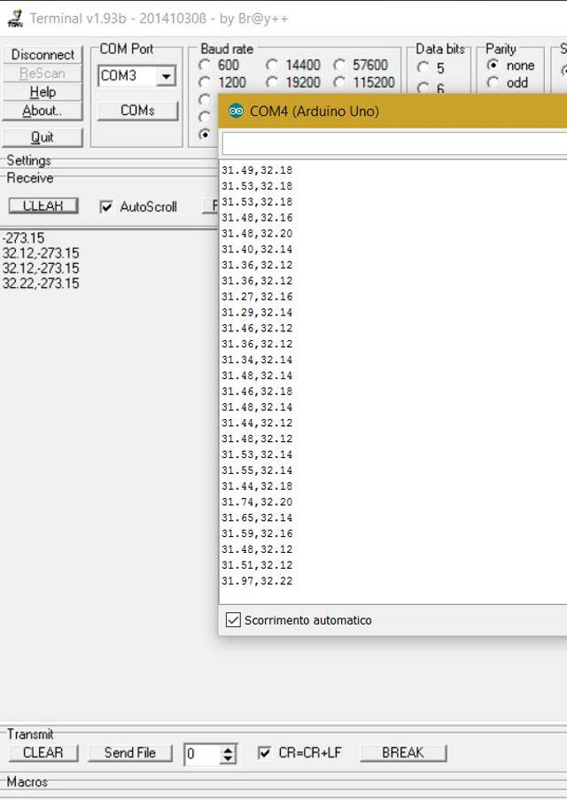
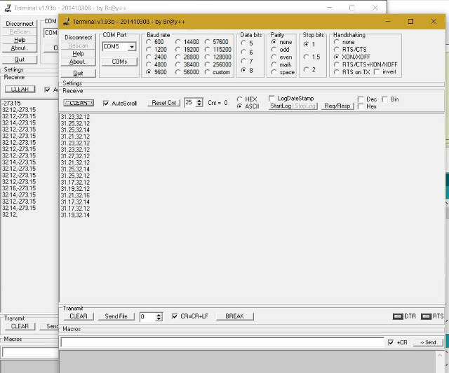
Master writer / Slave receiver temperature readings via serial terminal
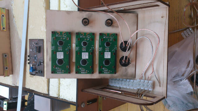
Set up of final test prior to mounting boards in the control cabinet
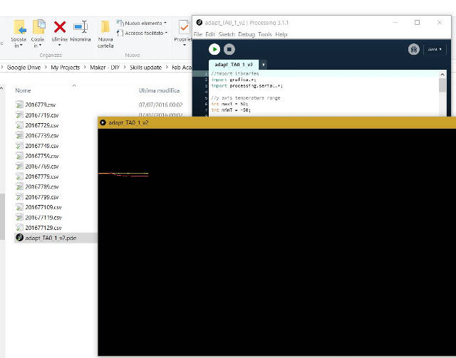
Final result: communication and PC application between Master writer and Slave Receiver
.jpg)
.jpg)
.jpg)
.jpg)
.jpg)