Testing the Peltier element
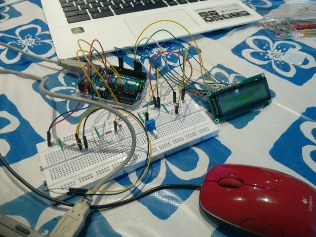
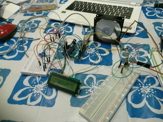
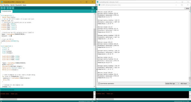
I made the first tests of the Peltier with an Arduino board and the Arduino IDE. Then I set off to integrate this practice in the dedicated final project boards.
I used a PID system for temperature control. The sketches therefore inlcude the relevant Arduino library (PID_v1.h).
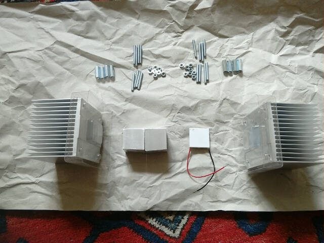
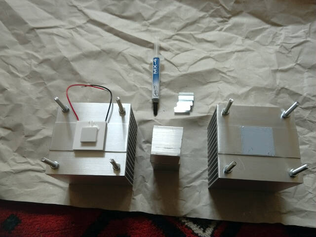
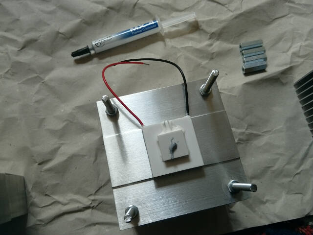
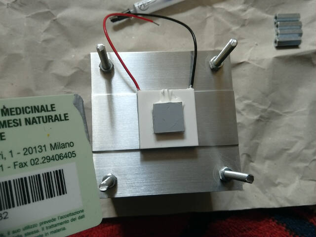
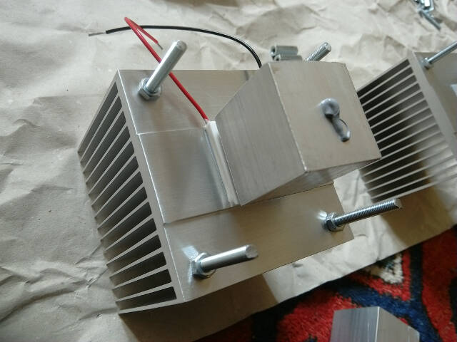
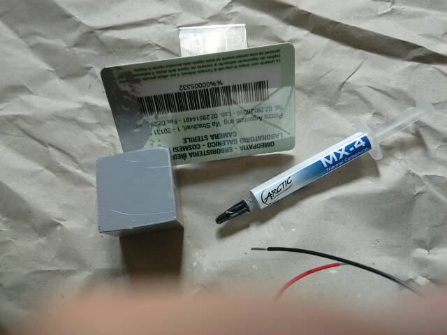
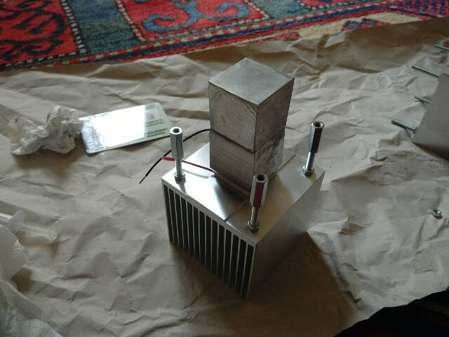
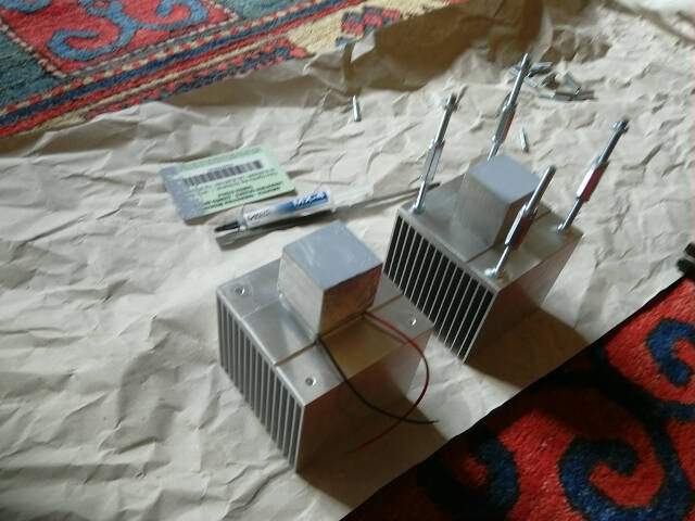
First assembly of the thermal group
In order to properly work and avoid demage, the Pelier element must be equipped with an heat sink. I therefore assembled what will then be the thermal group in the final project
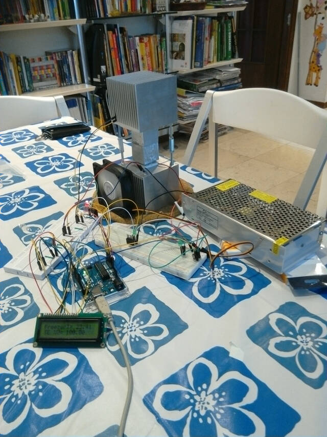
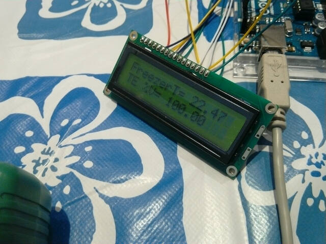
I adjusted the PID set point to an ADC value of 540 corrsponding to a temperature of 22.4 °C
I also connected an LCD to show temprature and percentage voltage to Peltier (also see the next section).
.jpg)