Make "hello-world" board
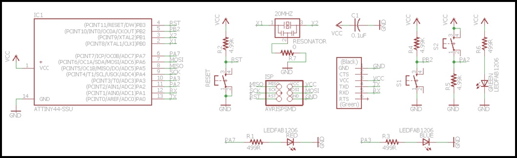
For this assignment, I have thought to add a Reset Buttom, pull-up resistor, pull-down resistor, leds and power-on indicator.
First I have sized de resistors with this tips:
- FabLab Yachay has only 4.99 and 1 ohm resistors series, then for pull-up and pull-down resistors I reviewed this page (Pull-up Resistors from Sparkfun) and I concluded to use 4990 ohm resistor.
- For the current-limiting resistors for leds I reviewed the LED datasheet and I sized the resistors with this page (LED CENTER).
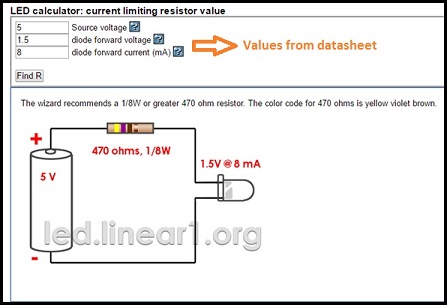
- The value was 470 ohm then I use 499 ohm resistors.
Now is time to design the PCB and there are the steps to do it:
1.- Download and install Eagle.
2.- Download FabLab library and move it to Eagle library folder.
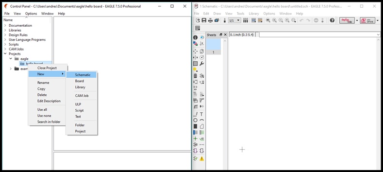
3.- Open Eagle, create New Project and add new Schematic File.
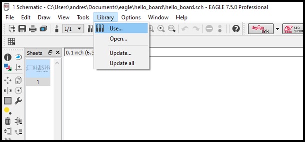
4.- Open Schematic file and go to Libary / Use and select fab.lbr to add FabLab Library.
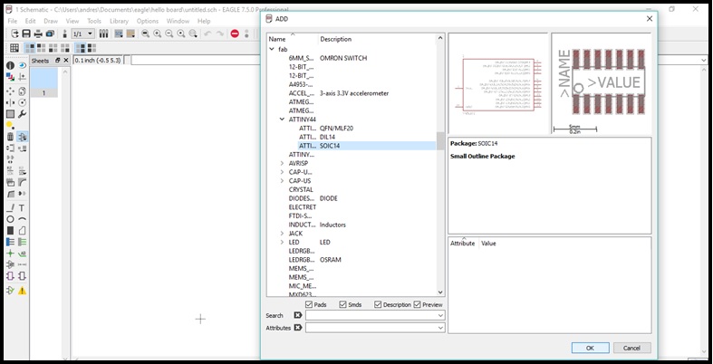
5.- Go to Edit / Add, browse and add all electronic componets for PCB.
6.- Wire the components.
7.- Push on Generate/switch to board buttom to open Board file.
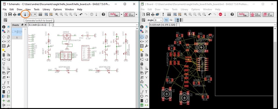
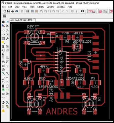
8.- Route the components and set the PCB border.
10.- Export as PNG file. Don't forget to export as Monochrome image and 500 DPI of resolution.
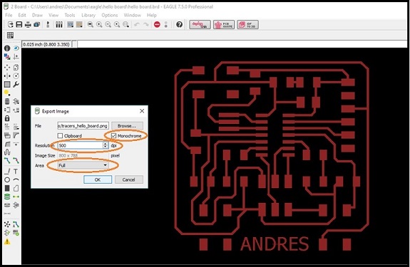
You can download Eagle files here.
Before milling the PCB is necessary to modify the PNG file:
1.- Open GIMP and open PNG file.
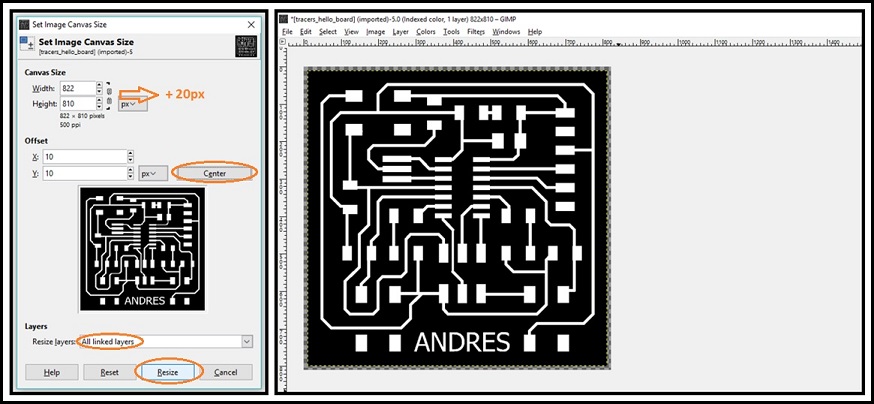
2.- Go to Image / Canvas Size.. and add 20 px border. Remember center the image and Resize with all linked layers.
3.- Go to Image and select Faltten Image.
4.- Save tracers image.
5.- Go to Tools / Paint Tools, select Bucket Fill and fill tracers except the border.
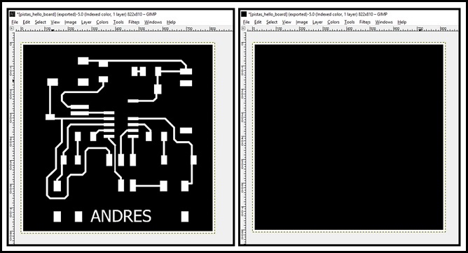
6.- Save cut image.
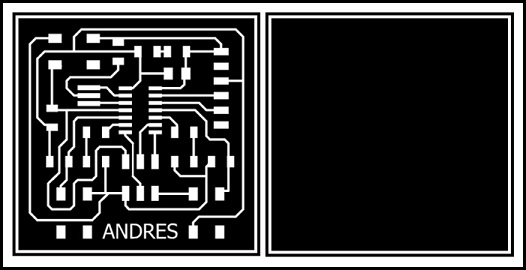
You can download tracers image here or cut image here.
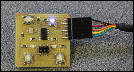
Milling the PCB and soldering the components.
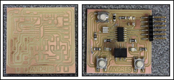
Testing power-on Led.
Extra
To simulate my PCB I have used Proteus, you can download the trial version here.
Create an schematic circuit in Proteus:
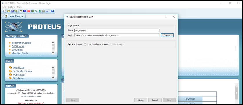
1.- Open Proteus and create New Project.
2.- Select the directoty and push on Next.
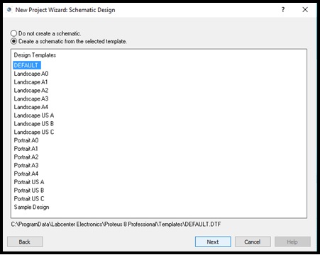
3.- Create an empty schematic file and push on Next.
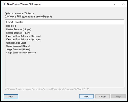
4.- In this time is not necessary to create a PCB layout becouse only need to simulate. Push on Next.
5.- Don't create firmware Project, push Next and Finish.
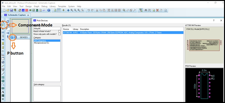
6.- Push on Component Mode button and push P button to open components library. Search and add the electronic components.
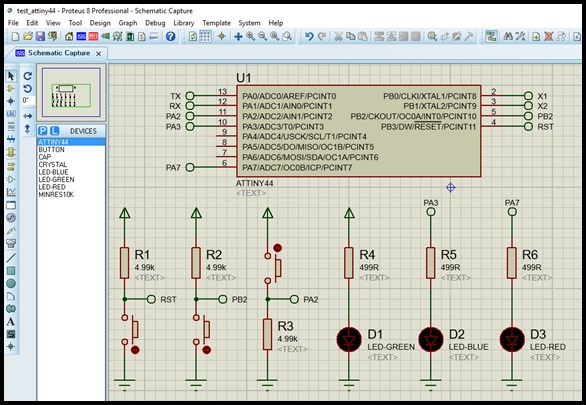
7.- Place and wire the components.
Programming ATtiny44 with Arduino IDE:
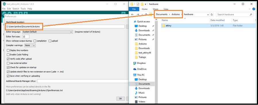
1.- Download and copy ATtiny board files on Arduino preferences path. Remember to create hardware folder.
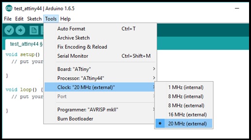
2.- Go to Tools and configure the board:
2.1.- Board: "ATtiny"
2.2.- Processor: "ATtiny44"
2.3.- Clock: "20 MHz (external)"
3.- Make a program: I have developed an algoritm to wait for press any button and increment or decrement the intensity of one Led, for this I have used a PWM output to control the intensity of LED. The other LED stays on while any button is pressed. Also, the micro transsmits the value of intensity through a Serial interface.
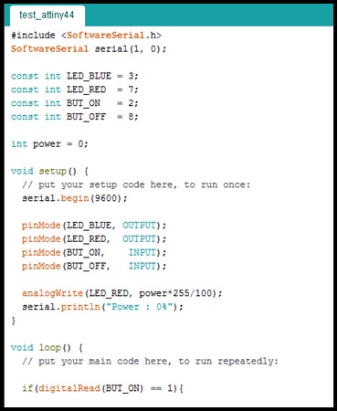
4.- Go to Sketch and select Export Compiled Binary to generate HEX file.
Simulate:
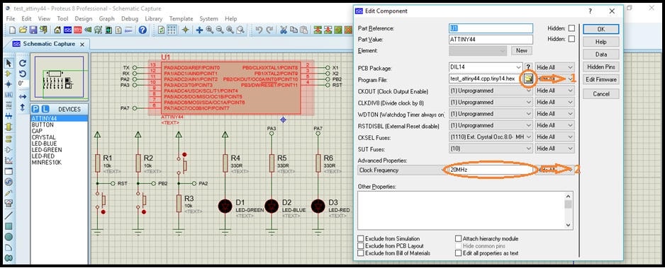
Now, is time to upload the HEX file in schematic circuit:
1.- Double click on ATtiny44 and push on folder button to browse HEX file.
2.- On Clock Frequency set 20MHz.
Add some Virtual Instruments:
1.- Push on Instruments button.
2.- Add Oscilloscope to monitore the PWM output.
3.- Add Virtual Terminal to monitore serial interface.
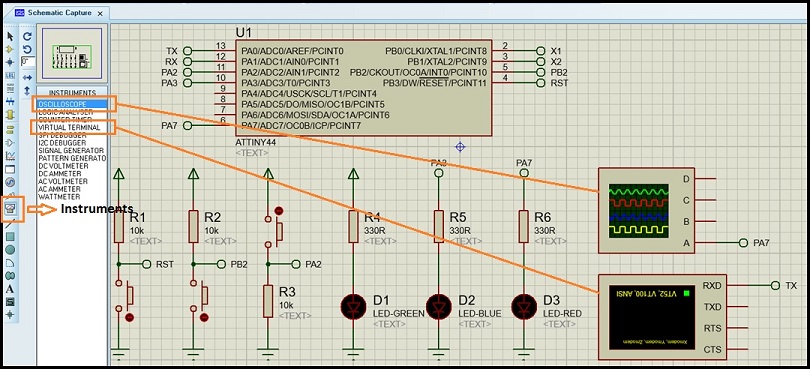
Finally push on Run button

You can download Proteus project, programming file and Hex file here.