Week 12 - Input Devices
Assignment
measure something: add a sensor to a microcontroller board that you have designed and read it
Planning
I reviewed Neil’s lecture and started making a list of sensors that seemed interesting:
- Ambient light sensor: useful for my final project
- Motion sensor: useful for my final project
- Step response: for its versatility
- Video: because I’m interested in gesture recognition
Ambient Light Sensor
I decided to take this up first, since it would be used in my final clock project to detect ambient light and turn off the display when its completely dark.
This uses a phototransistor, specifically this one.
Here is Neil’s board layout:
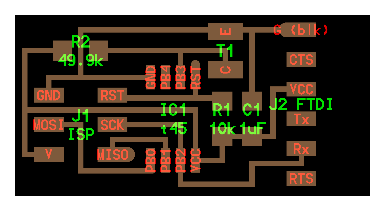
Neil also demonstrates a technique called synchronous detection, which allows you to differentiate a reflected light (which you control) from ambient light. I could use this for simple gesture recognition in the clock.
Here is the light reflect board, it adds an LED and a resistor to the previous board.
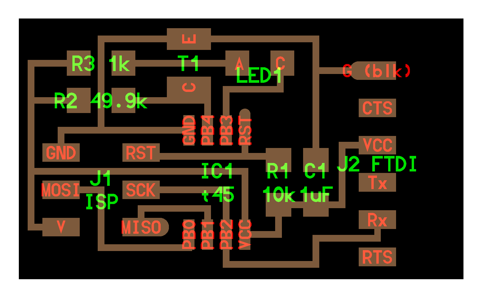
I’m going to make the reflect board, because it could possibly allow me to use a simple LED instead of Infrared emitter / sensor to detect hand movements.
Drawing the board in Eagle
First step is to draw the schematics in Eagle.
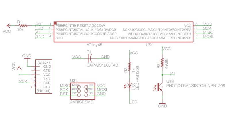
Looking at the board above, I’m not sure why the RX pin (instead of the TX pin) of the FTDI connector is connected to PB2. This might be to not require swapping of TX / RX jumper cables.
Some questions to revisit:
-
How is the capacitor value calculated to be 1µf?
- Why is R2 so high at 49.9K ohms?
- This is explained well here. The phototransistor lets more current pass when more light falls on it. Having a large resistor in series allows small current changes to be detected as large voltage changes.
- Why does the phototransistor not have a base lead?
- Explained here, the base is left unconnected because light is used to enable current flow through the phototransistor.
Here is the schematic:
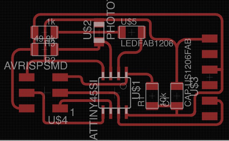
and here is the layout:
Here are the original files:
- Schematic: w12-reflect.sch
- Board: w12-reflect.brd
Board Production
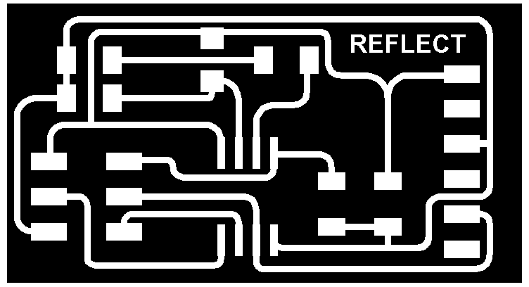
Next I exported the traces and outline PNGs. Then I edited these in GIMP to add some text and borders:
Traces:
Outline:

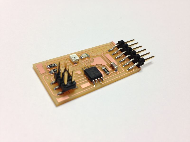
Stuffed board:
Programming
When I tried to program the board, it gave an error “not initialized, check connections”.
I looked at the board carefully and realized I had missed soldering the MISO pin. I soldered it and the board got programmed fine.
I tested the board using Neil’s code and the python app showed the readings for ambient and reflected light. Here’s a demo: