Mechanical and Structure Development
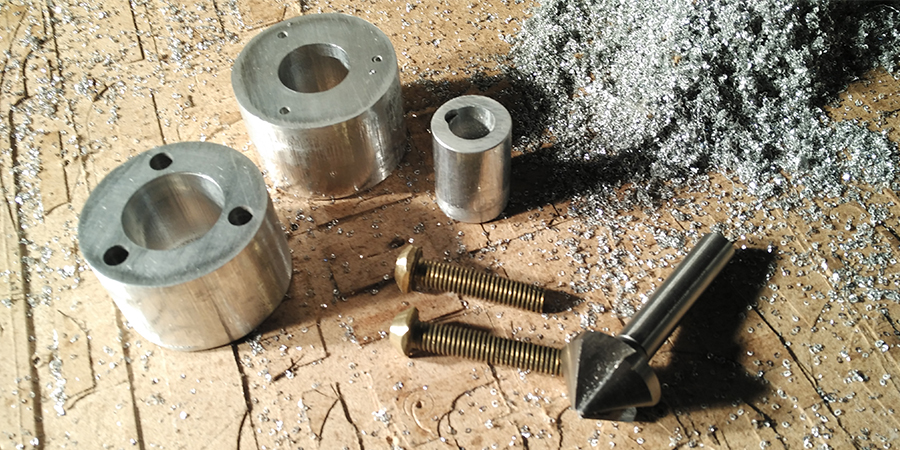
Source filesThe extrusion system is composed of an
auger bit, that transports the pellet from the hopper, to
the heater; that it's composed from an aluminum hotend with three
ceramic heater cartridge and a thermocouple that control the temperature.
The material begins to heat in the aluminum pipe during the transports, and
arrived to the hotend will be melted and pushed out the nozzle.
All the aluminum parts are CNC milled except the pipe, the milling process is the same described in the
CNC tutorial.
The aluminum milling was very similar to the wood one, I have used mainly
a 6mm straight cutter,with a Feedrate x,y of 600 mm/s,
a Feedrate z of 80 mm/s, a
Spindle speed of 10.000 rpm and a Step down
of 0,3 mm.
One important thing will be to use an cutting lubricant, that will
help to have a good result.
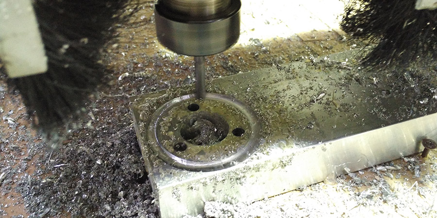
A very important step is to add enough tags, in order to avoid that the piece vibrate, I have used 3 tags 3mm thick.
Hotend CNC milling.
A very important step is to add enough tags, in order to avoid that the piece vibrate, I have used 3 tags 3mm thick.
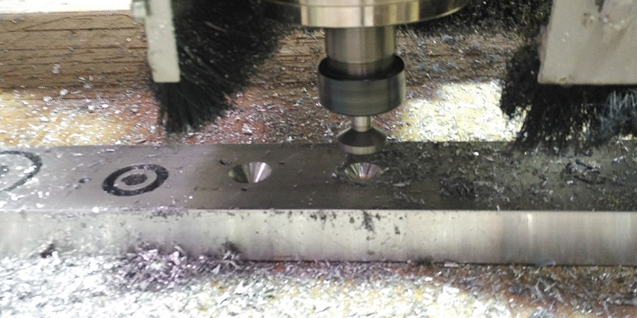
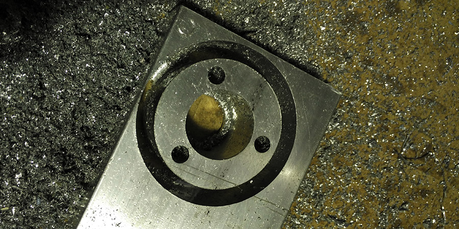
To milling the cone for channeling the material towards the nozzle I used a 45 chamfer bit.
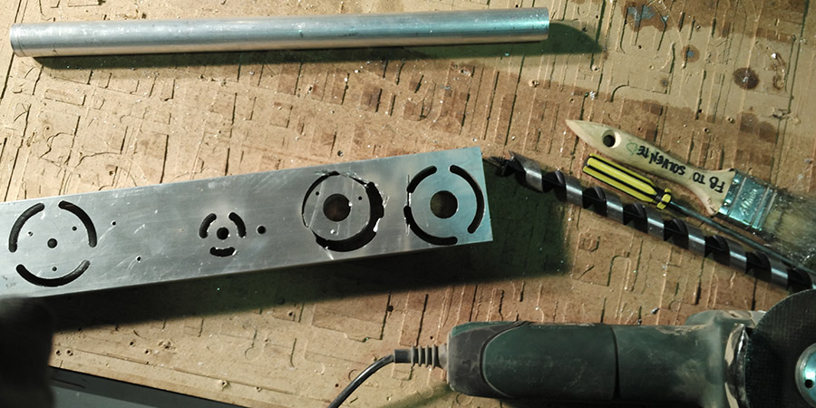
Remove the pieces from the aluminum block was a little bit tricky, because the thickness of the tags, so I used the Dremel, and after I have refine with a grinder.
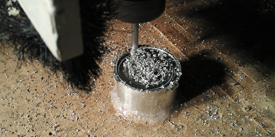
The middle part of the nozzle needed a machining on both side, so after
the first machining I have fixed the piece with a couple of screw and some
hot glue.
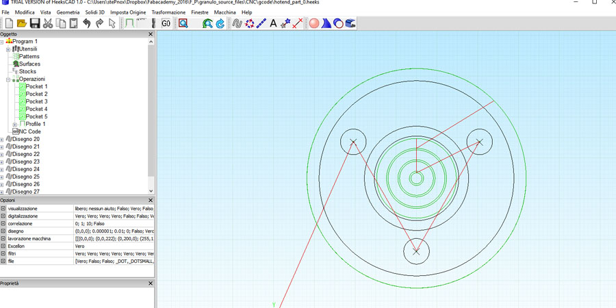
Here all the cad and
CNC file to mill the hotend parts.
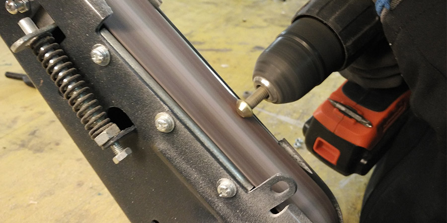
In order to obtain an interchangeable noozle, I have used an M8 brass bolt that I have drilled to the center and turned the top using a battery drill and a bench grinder.
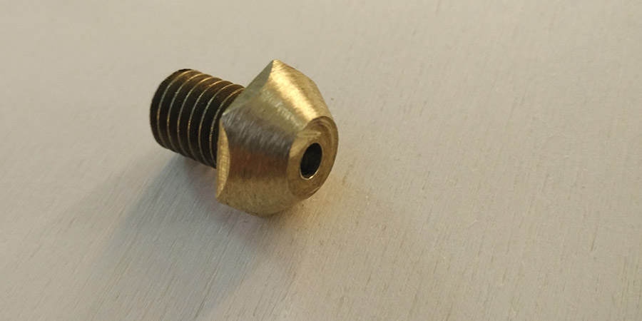
A 4mm noozle ready to use.
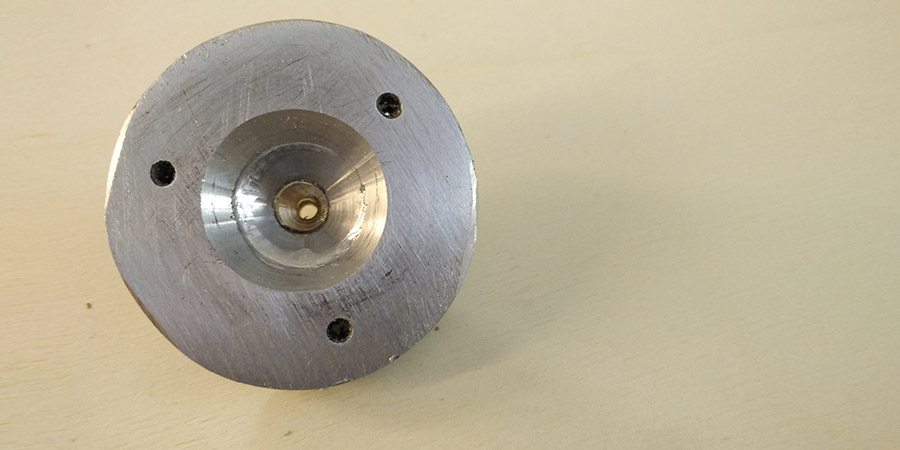
The noozle mounted on the hotend.
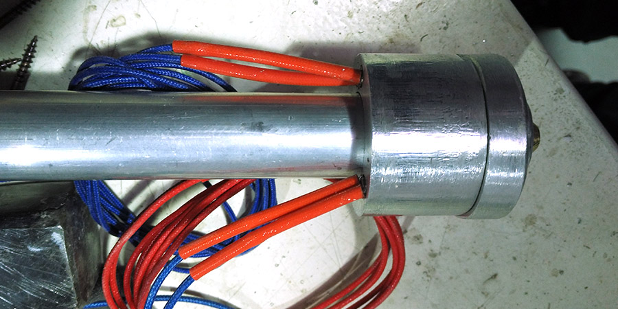
The aluminum pipe is connected to the hotend using a couple of M4 bolts on the side of it, here the system connected.
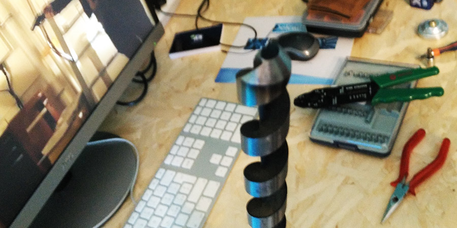
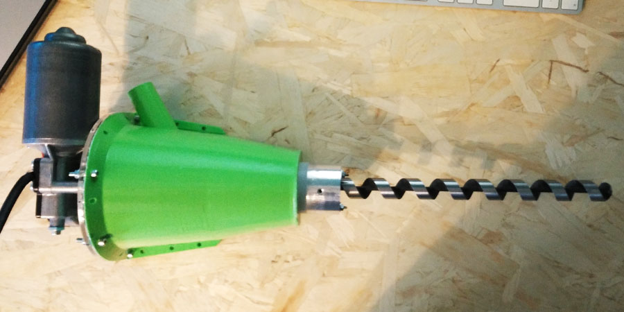
The auger bit was turned using the system described above for the noozle. In this way the end of the auger bit have the shape of a truncated cone that help the extrusion of the material through the noozle.
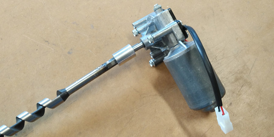
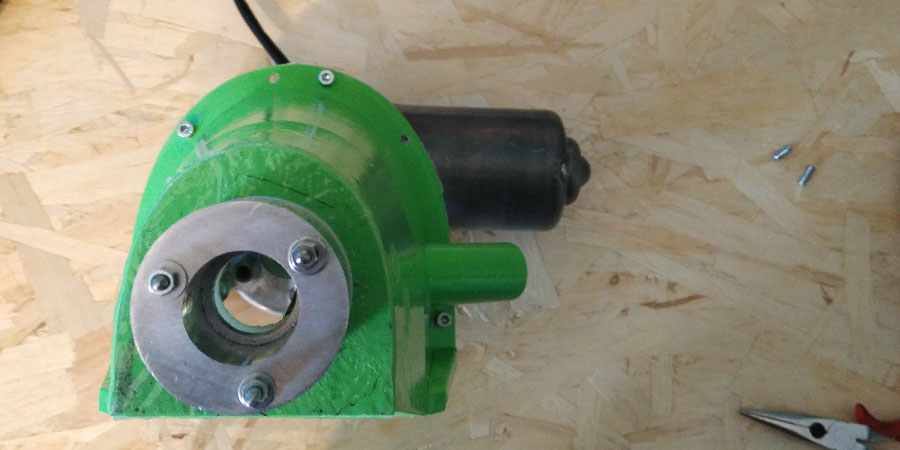
In order to coupling the auger bit with the motor shaft I have CNC milled an aluminum piece with the holes on the sides in order to block the shafts.
The Structure
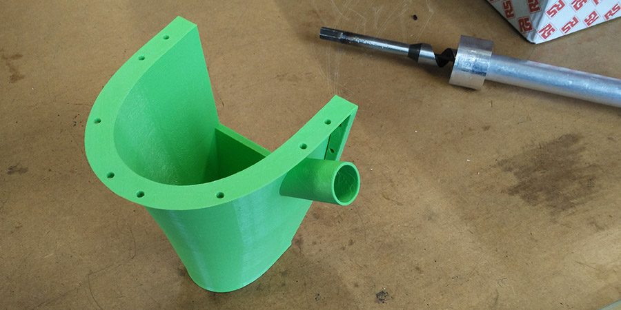
The hopper is designed to convey the materil to the auger bit and in the same time is the central structure where the entire system is anchored and connected to the 6th axis of the robot. On the side there is a connector used to fill the material by hand or using a tank connected throug a pipe.
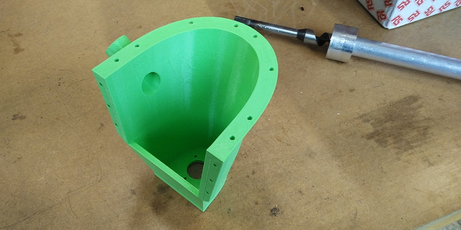
The main structure is 3D printed using a classic delta FDM one, the process used is the same described in the 5th module of 3D printing and scannning.
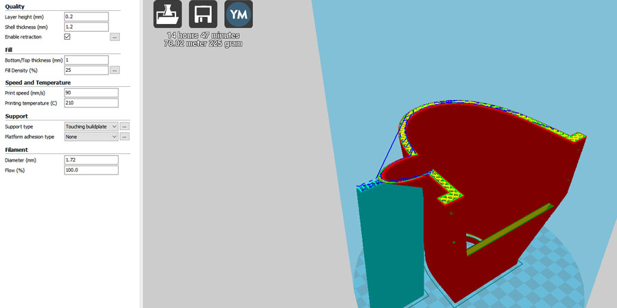
The mani printing parameters used are:
Layer height: 0,2mm, Shell thickness: 1,2mm,
Bottom/top thickness: 1mm, Infill: 25%, Print speed: 90mm/s,
Printing temperature: 210 C.
Here the .stl model
and the printing profile for Cura.
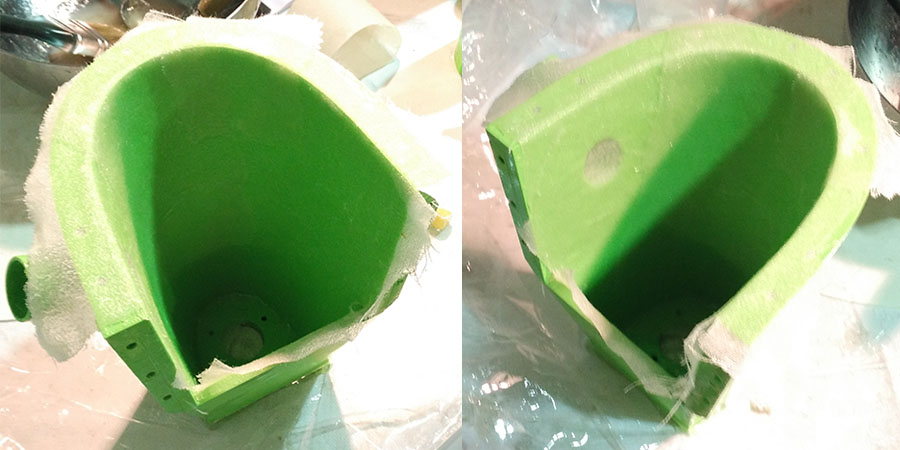
In order to have a better tensile strength I have fiber-reinforced
the 3D printed PLA hopper, using epoxy resin and linen.
The results are very very strong pieces!
The process used is the same described in the
13th module of the Composites module.
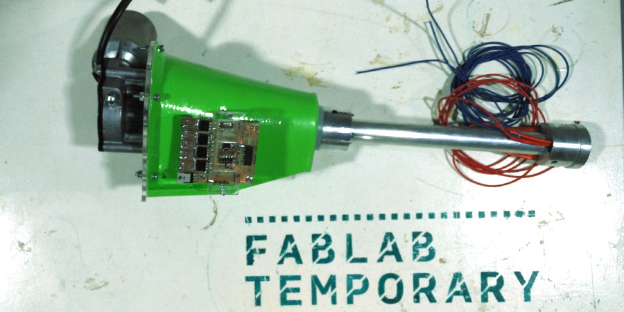
The Flange
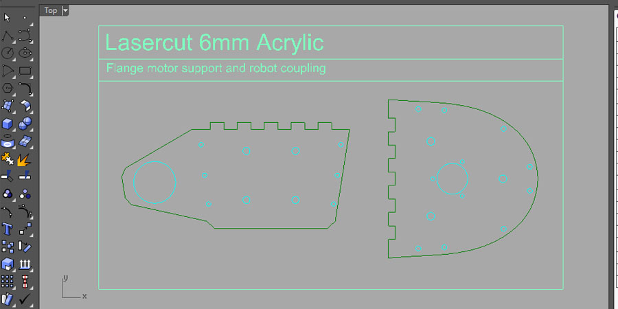
The flange is composed from two laser cutted pieces of acrylic 6mm
thickness.
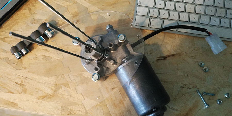
The first one is needed to fix the motor to the hopper in order to have
an easy way to mount and unmount the system.
The second piece is needed to mount the extruder to the 6th axis of the robot.
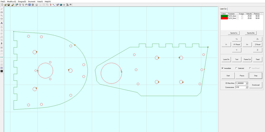
The process used is the same described in the
3th module of 3D computer controlled cutting.
The main cutting parameters used are:
Cutting speed: 25mm/s, Power: 90%,
Corner power: 70%.
Here the .dxf model
and the cutting file for LaserCut_6.1.
The Extruder
Extrusion test.