#Exercise_3
10/02/2016
Assignment
Lasercutter- Demonstrate and describe parametric 2D modelling processes
- Identify and explain processes involved in using the laser cutter
- Develop, evaluate and construct the final prototype
Hangable Organizer v_2.0
Design of the AlgorithmFor this project I decided to start from an old opensource Fablab Torino project Hangable Organizer, a lasercut box to organize the work space. We use this boxes to organize our screws, bolts and washers; now we need something similar but smaller and with a transparent front to organize the electronic table.
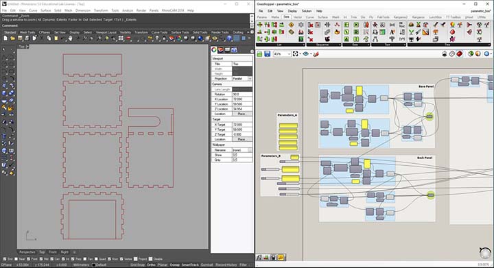
The first and most important thing will be to decide the parameters that will resize the boxes, and set up the algorithm.
In the grasshopper canvas is easy to make some confusion (I have spent a lot of time to do the reverse engineering of my algorithm), so my advice is to subdivide the algorithm with the group tool and use the panel component to take some notes about wath we are going to do.
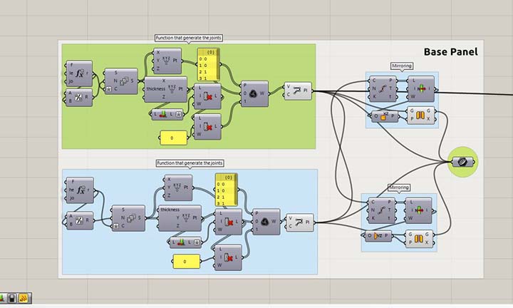
Aftre the defination of the parameters, I have set up the algorithm to generate the joint path. To do that I have worked with points, series of numbers and list modifiers; at the end I have used the poliline component to generate the vector.
This one will be the base function that I will use to generate all the peaces joint structure. The formula test the division for odd number or not and decide to add or not +1.
To generate the joint path, I have write a custom formula to adjust the lenght of the teeth. (we can see in the img_3)
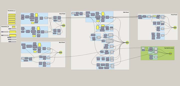
All the peaces that compose the boxe are obtained by using the joint function and other bases manipulation.
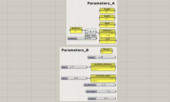
Defining the parameters of the boxes. [img_1]
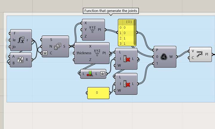
Function that generate the joints path. [img_2]
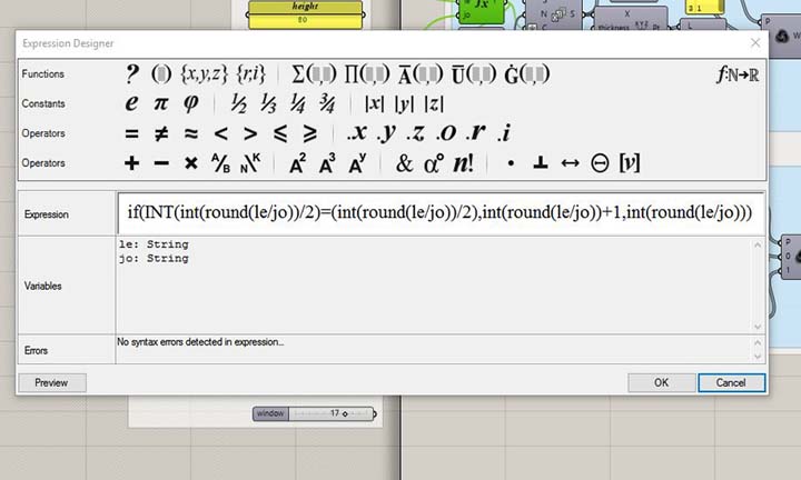
Custom formula. [img_3]
Base panel peace. [img_4]
Lasercut set-up!
At the end I have backed all the curves from Grasshopper to Rhino, and prepared the file in order to obtain a good result with the lasercutter.
- Check the unit if is mm
- Check for double lines
- Check if polylines and not a lot of segments
- divide in different layers for each cutting pen
- export the file in .dxf natural 2004
To cut the boxes I have used this WORKLINE laser cutter, the machine has a work area of 1200x900mm and a 130W CO2 laser tube.
The software needed to generate the machine code is LaserCut_6.1
The materials used are:
- 3mm cardboard (prototype)
- 3mm plywood birch
- 2mm transparent plexiglass
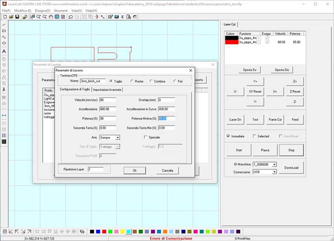
2nd step: we are going to define a new cutting pen for our material (3mm plywood). From the button working parameters, we will add a new one, select the cut type, give a name and after some test on the material set up all the parameters.
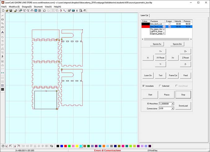
3rd step: now that we have set up the 3mm_birch_cut, from the layers side bar we will select this one to both our layers (cut_in and cut_out). We can adjust the sequence of cutting of the layers by moving each one up or down.
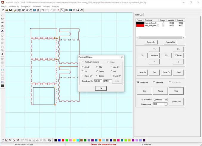
4th step: from the top bar we use the select origin point function, to set up the position were we want to start. We can decide to use a relative position from the laser head or the absolute position in the working area.
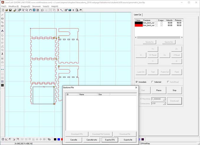
5th step: we are ready to compile and upload the machining file in to the lasercutter. We will use the "download button">"download current file"> now we will put a short name to our file, press enter and all is done! Please, pay attention to the translation of the software ( we are going to upload the file into the laser and not download it from).
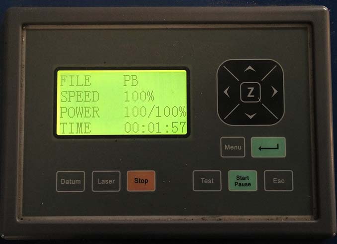
6th step: now that we have the file ready to cut, we must select in the menu from the control panel.
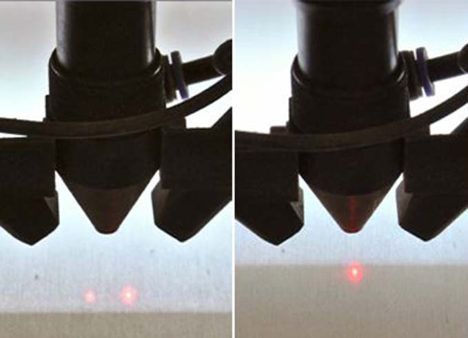
7th step: now we must just adjust the focus on the machine operating whit the Z axis on the control panel, when the two laser pointers become one point the focus will done.
8th step: put the pointer were we want to start to cut, press the tes button to make sure the cutting area will be right and press start to cut. Before cutting make sure that the chiller and the aspirator are turns on.
Assembly the Prototype!
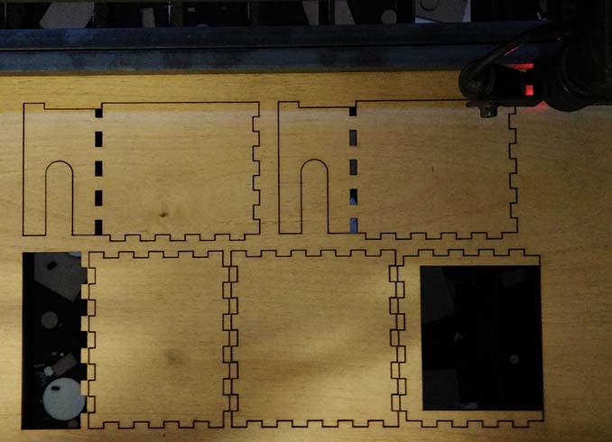
With a couple of tester I can try to assemble it and evaluate the right tolerance.
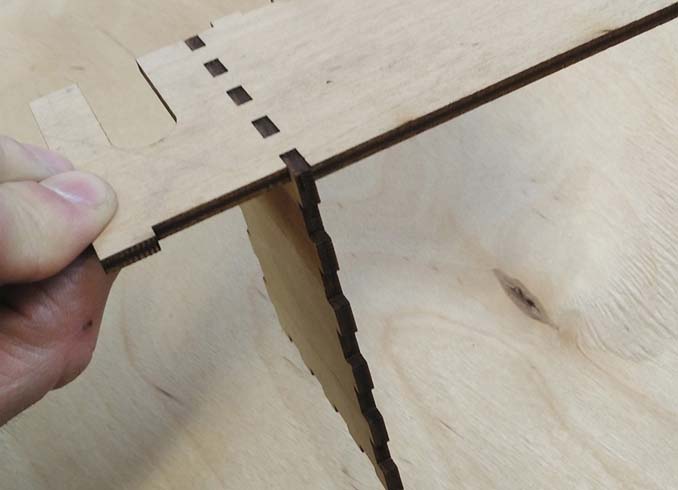
1rst step: test the joints and evaluate the right tolerance to adopt to have a good press-fit.
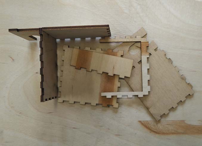
2nd step: cut all the missing parts.
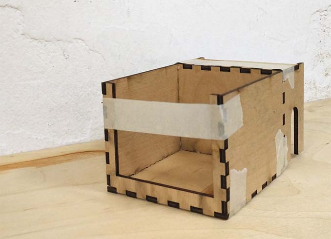
3rd step: fit all the parts and glue it were need it, wait some moment.
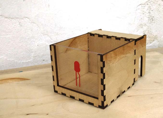
4th step: the boxe is ready to use!.
Vinyl Cutter!
I'm going to cut the stickers icon for our boxes, and make it easy to identify. So I decided to start from the Fritzing electronic icons, in this way will be more familiar to the users.
To cut the stickers I have used the Roland GX-24 vinyl cutter, the maximum cutting area is width: 584mm and length: 24998mm.
The software needed to generate the machine code is inkscape usign the plotter like a normal printer.
The materials used are:
- red vinyl
- blue vinyl
- transfer tape
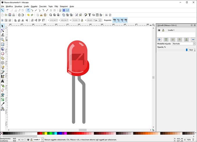
1rst step: import the .svg file from the inkscape library; this file is not good for our porpouse, because was designed to graphic purposes.
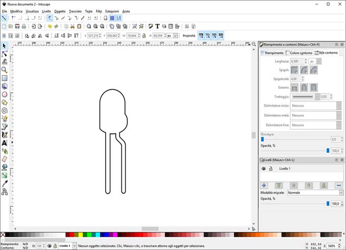
2nd step: here I have modified the drawing, delete all the shapes that we don't need, make some boolean union and make outline.
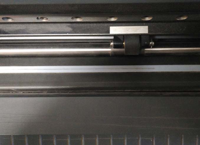
3rd step: load the vinyl roll, here is need to pay attention when fix the little rollers, they need to stay in the white area; at the first time one move and I found a blicking error.
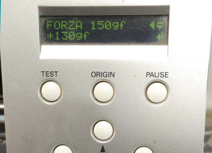
4th step: set up the home position and the force up to 120g; after making a couple of test I set up the force up to 130g.
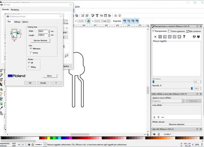
5th step: now we are ready to print; going to File >Print >select the vinyl cutter from the available printers and click. Set up the unit in mm, get the cutting area from the machine using the button. In the setting panel set up the cutting speed at 10cm/s and Print!
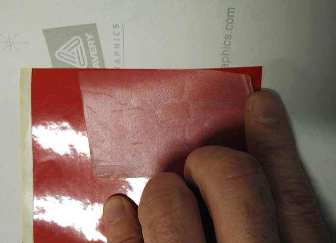
6th step: after the finishing we can cut out our sticker and then we have to put the transfer tape.
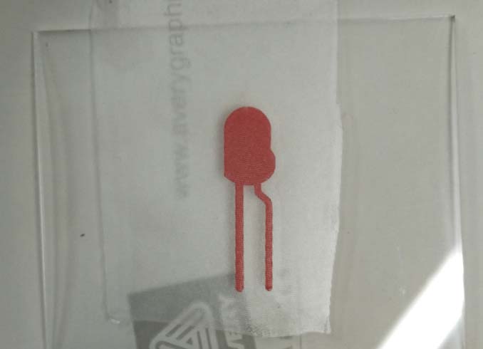
7th step: finally I clean the plexi and put the sticker on pushing a little bit!
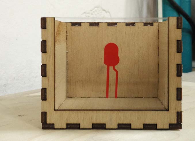
8th step: the final step was to remove the transfer tape.
1rst step: import the .dxf file that we have prepared; the software will accept different type of vector files, but the only one free from any problem will be the .dxf 2004.