#Exercise_10
13/04/2016
Assignment
Input DevicesMeasure something: add a sensor to a microcontroller board that you have designed and read it.
Design the controller board for the final project
Source filesFor the assignment I decided to design the first prototype of the controller board that I will use for my final project. So I organized the two exercise, input and output devices together.
To control the pellet extruder I will need a ceramic heater cartridge in order to heat the noozle, a thermocouple to control the temperature, a thermistor or a temperature sensor to mesure the ambient temperature, a DC geared motor for the extrusion and a solenoid valve to cool the extruded material.
BOM
- 1 X Thermocouple J type
- 1 X Thermistor
- 3 X Ceramic heater cartridge 24V 40W
- 1 X DC geared motor 24V 5Nm Torque
- 1 X Solenoid valve
- 1 X Power supply 24V 15A
- IC1 AD594 Amplifier
- MICRO ATMEGA328P-AU
- Q1 16Mhz Crystal
- C1, C2 18pF
- C3, C4 100nF
- R1-R8 10K
- R8, R9 0ohm
- Q2-Q5 IRF3710S N-FET 100V 57A
- Q7 IOR
- D1-D5 DIODE 1N4001
- 7 X Screw terminal
- 1 X MTA02-156 male connector
- 1 X RJ45 female connector
- 1 X SMD male header 5X2 connector
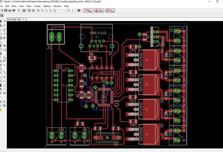
Board: on the board I have used a couple of through hole components, and soldered bending the feet.
The ISP connector have 10 pins becouse I have added the RX an TX in order to allow the serial communication, that will used to communicate with the robot, but to make easier the wiring I have installed an RJ45 connector too. The robot core and the extruder control board will be 7m distant.
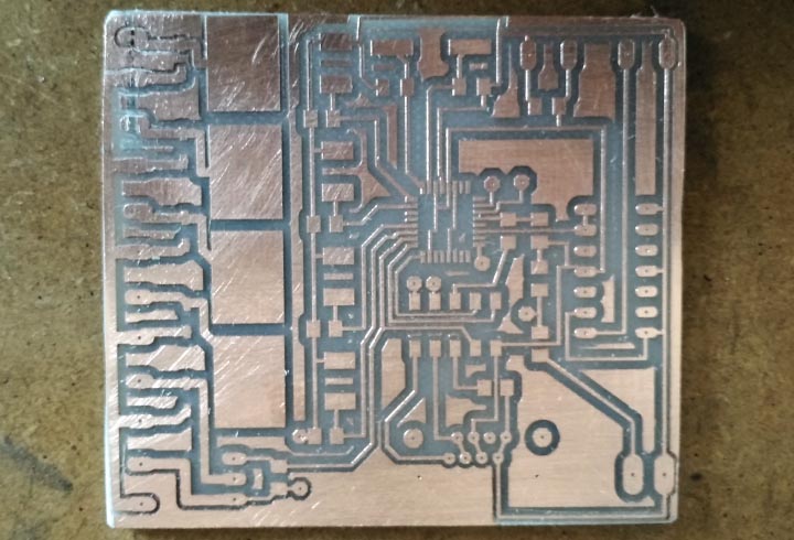
Milling: milling the board was pretty tricky, because the 328P-AU have a very tiny footprint, the pads are very close each oder (only 0,25mm). To mill the board I have used the same process described in the electronics production module.
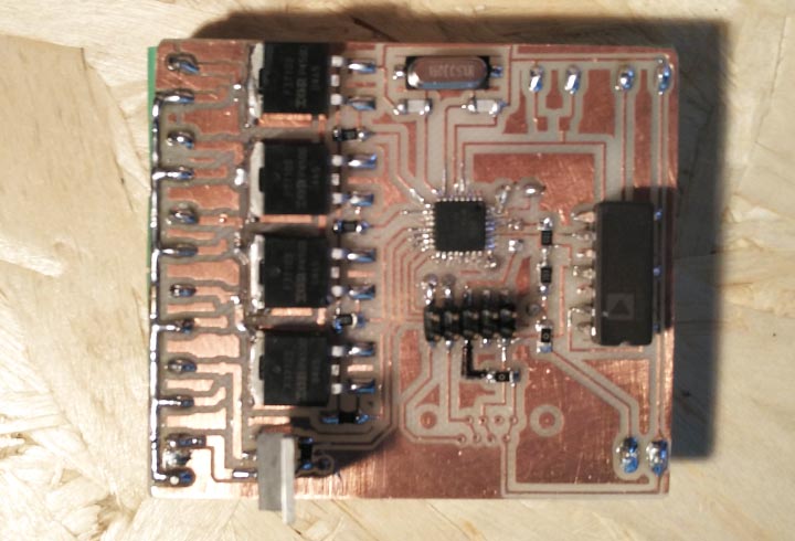
Soldering: the board have a couple of wires on the bottom layer in order to connect the via. I have soldered all the screw connectors on the bottom layer.
As I immagin solder the 328P-AU was tricky too and took some times.
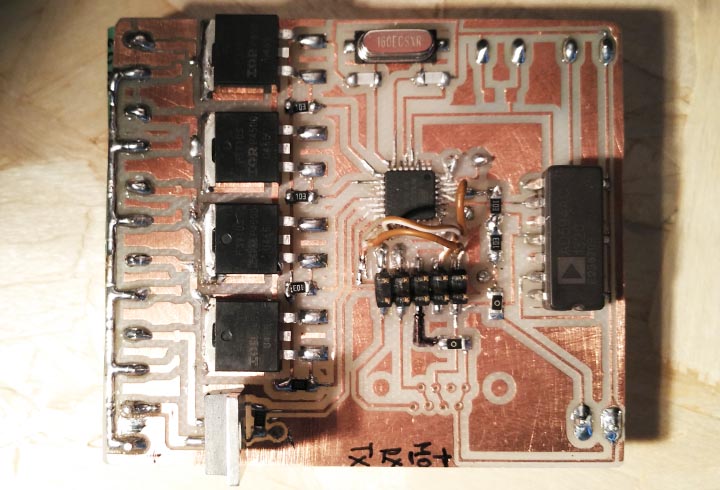
Some Problems: the first connection to the computer has not been a success, because I'm not been able to program the board. After a debug with the multimeter I discovered a short under the ISP connector; So I fix it cutting some tracks and soldering a couple of wires.
Input testing usign the serial communication, we can see the temperature increase using a lighter near the thermocouple.
Input testing usign the Arduino serial plotter, we can see the temperature increase on the chart using a lighter near the thermocouple.
Arduino Input code
					//define the thermoc. pin
					#define TC_1 A4

					void setup() {
					  //initializa the serial port
					  Serial.begin(9600);
					}

					void loop() {
					  //read the analago pin
					  int sensorValue = analogRead(TC_1);
					  //convert the voltage to temperature
					  float voltage = sensorValue * (5.0 / 1023.0) * 100.0;
					  //print the temperature on the serial monitor
					  Serial.println(voltage);
					  //wait a second
					  delay(1000);
					}
The code: this simple sketch read the temperature from a thermocouple. In this code I convert the analog read to a voltage and after print on the serial monitor the temperature.
Upload the code: as described in the Embedded Programming module to upload the code on the board I have used the Arduino IDE and the FabISP, the first time I have burned the bootloader in this way I can use the board like an Arduino UNO using only an FTDI converter to upload new sketch.
The code has worked well as expected.
Output Devices week
Board: I decided to usa an ATMEGA328P-AU insted of using the Attiny44, because I will need a lot of PWM ports and the hardware serial, in order to allow the comunication between the robot and the control board.
To control the nozzle temperature I will use a thermocouple to allow a very accurate measurement; so I have installed the AD594 in order to read the data from the thermocouple type J.
To heating the nozzle I use 3 Ceramic heater cartridge, so I will need 3 mosfet to allow the control of the heating and other two to control the DC geared motr and the Solenoid valve.