#Exercise_4
17/02/2016
Assignment
Electronics productionThe assigment is related to producing a PCB. We were asked to mill, and program the Fab ISP board, that allows to program AVR microcontrollers.
- Make the Fab (tiny)ISP in-circuit programmer
- Describe the process of production
- Demonstrate correct workflows and identify areas for improvement
Fab ISP
Prepare the g-codeI have used Eagle with the pcbgcode, a very powerful plug-in that allow to generate the gcode from the board file.
For this board we have used a 13 mils (0,33mm) traces width and 1206 SMD components, mounted on a single side copper board of 0,035mm copper thickness.
Source file - based on the David Mellis version, modified by Federico Vanzati, Gianfranco Caputo and Stefano Paradiso.
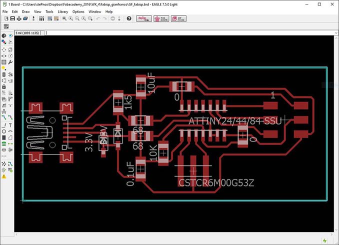
- n. 1 ATTiny 44 microcontroller IC1
- n. 1 Ceramic resonator 20MHz Q2
- n. 1 Resistor 68 Ohm R1, R2
- n. 1 Resistor 1.5K Ohm R3
- n. 2 Resistor 0 Ohm R4
- n. 1 Resistor 10K Ohm R10
- n. 2 Zener Diode 3.3 V D1, D2
- n. 1 Capacitor 0.1 uF C1
- n. 1 Capacitor 10 uF C3
- n. 1 USB mini connector
- n. 1 2x3 pins connector
- Single side copper board
- Roland MDX-40A
- V shape PCB bit cutters 0.1mm
- Lubricant grease
- Double side tape
- Tape
- Flute spiral bit 2mm
- Tweezers
- Pond 0.7mm
- Flux
- soldering iron
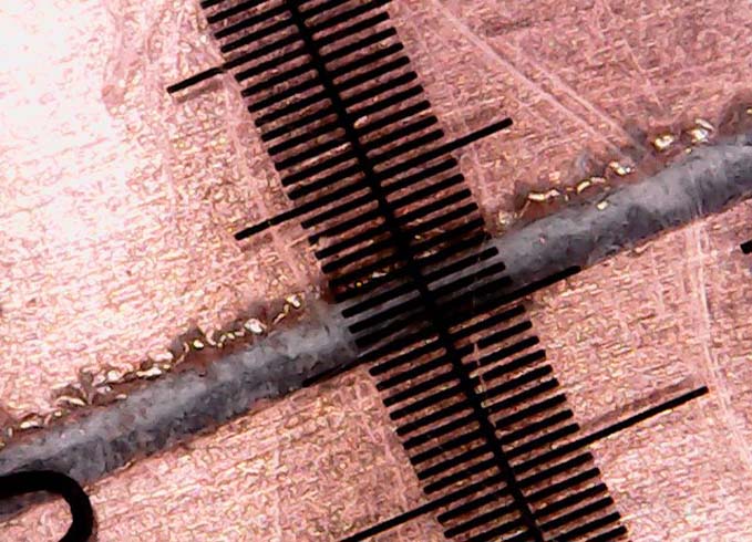
Testing trace thickness
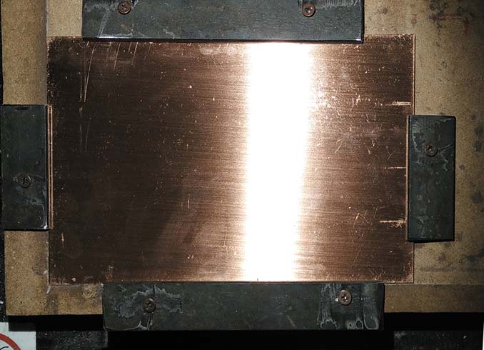
1rst step: Fix the PCB to the plate.
note: we got better results with a rigid stop than using the double-sided tape and the american tape for the edges.
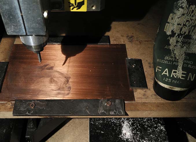
2nd step: smear a little drill bit of grease to reduce friction and reduce the bit consume.
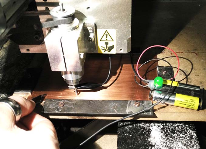
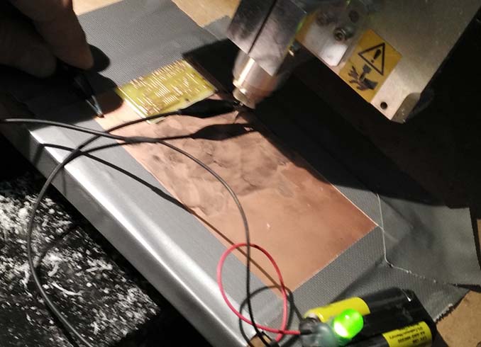
3rd step: set up the Z high, using the LED tool. I have I have checked the z in four different points; the deviation was only -/+ 0.01mm instead of -/+ 0.04 with the double-sided tape.
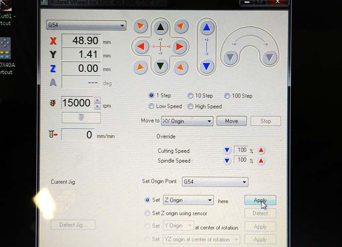
4th step: using the Roland V-panel I set-up the x,y,z origin.
5th step: I have made a line with V shape PCB bit at the z -0.1mm; the trace obtained results to have a thickness of 0.37mm.
Generate the GCODE and mill the board
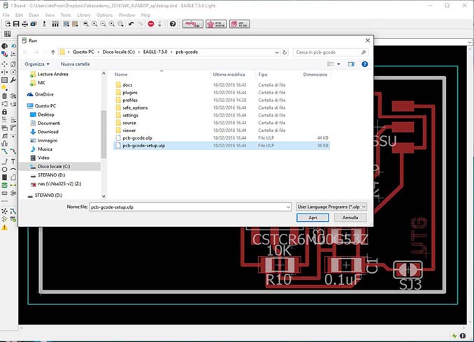
6th step: Run the pcbgcode plug-in File > Run ULP > pcbgcode-setup.
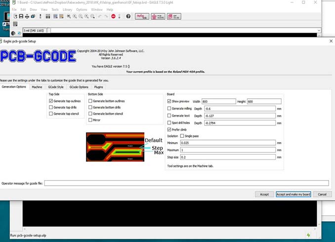
7th step: Set up the general options, considering the thickness of the test before.
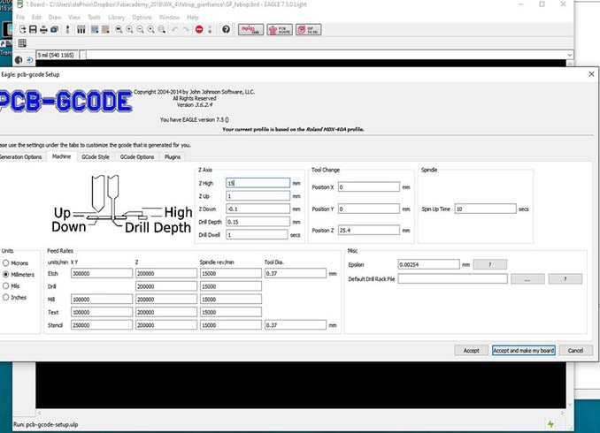
8th step: set up the machine options, pay attention to the speed parameters, for the Roland machine will be necessary to multiply the speed x1000. The z down is -0.1mm; tool diameter 0.37mm and x,y speed 300mm/min.
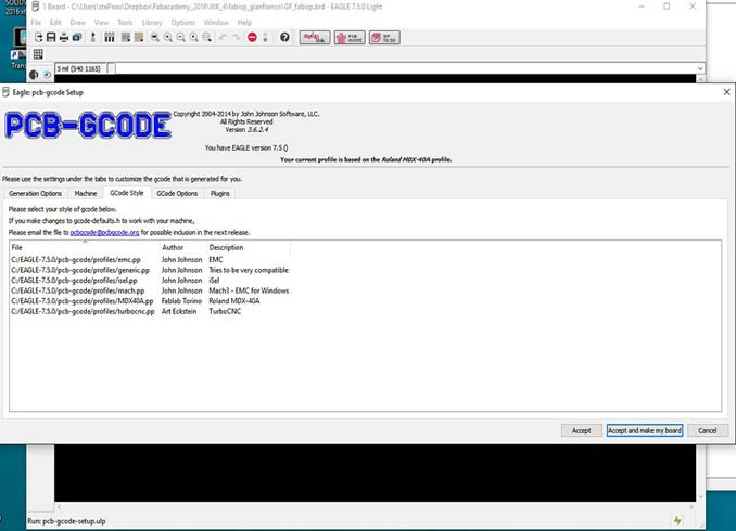
9th step: we have modified the post processor to have the feed rate F300000 and not F300000.00 (Roland problem), the next step to improve in the post processor will be the speed moltiplayer.
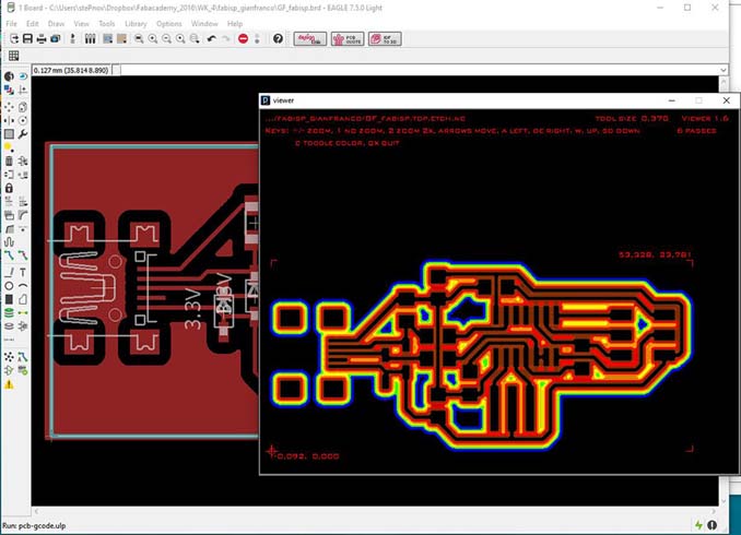
10th step: accept the parameters and generate the gcode file .nc, from the preview we can make some check.
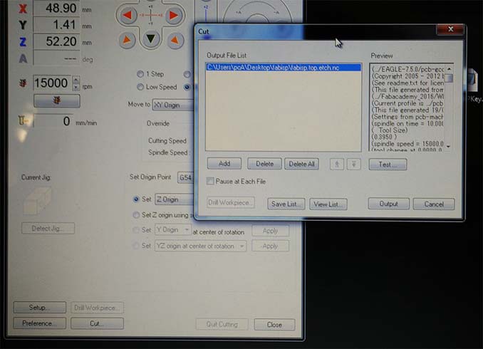
11th step: from the Vpanel press the CUT button, press ADD and select the file prepared before; we can test it and after press the OUTPUT button to start to mill.
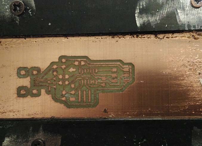
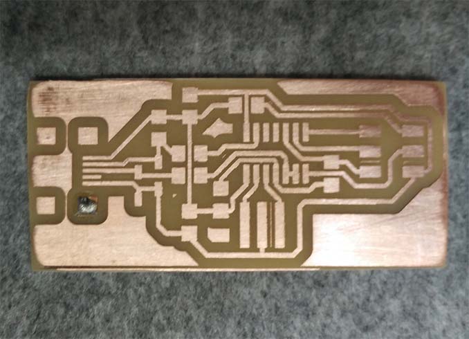
12th step: the result seems to be good at a first look.
13th step: aftar I sended and cleaned the PCB with the dish soap. The shorts checking with the multimeter was good, no shorts.
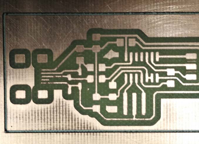
14th step: the checking at the microscope of the trace thickness was very well, I obtained 13mils traces (test before send it).
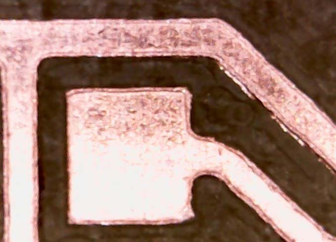
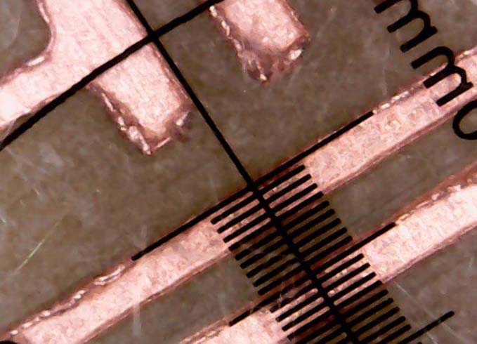
15th step: macro of the traces after send and clean it.
Solder the FabISP
I had already made some PCB before, but only using through hole parts and never soldered SMD components. I was a little bit scared because of my shaky hand. But in the end after a little practice I was able to solder all the circuit.
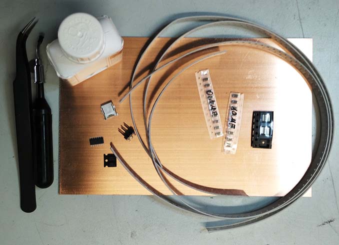
1rst step: prepare all the components that we need as the BOM.
2nd step: I'm starting to solder the USB mini connector, becouse is the component with the closer pads. Starting from the foot, I have stopped the connector and than soldered all the other three feet, at the end I put a little bit of flux on the pads and solder it.
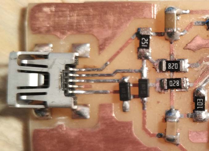
3rd step: after I soldered all the diodes, the resistors and the capacitors. That was not so hard, but take a lot of time.
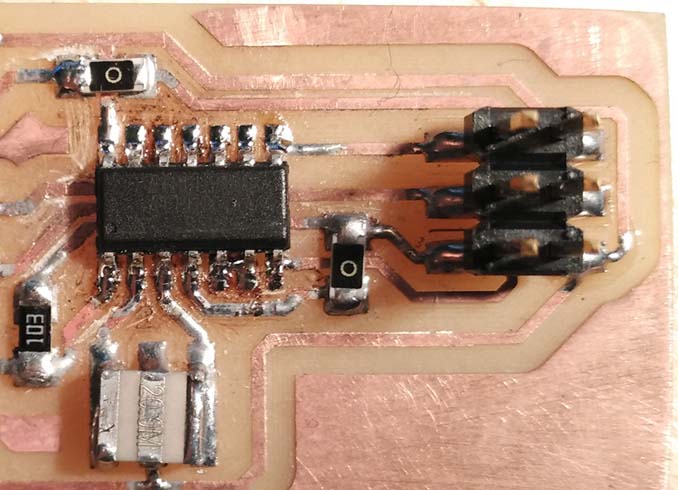
4th step: at the end I soldered the resonator, the connector and the last one the Attiny44A, but I had to desolder it because I did a short of the traces under the Attiny. The second time all was good.
Programming the fabISP
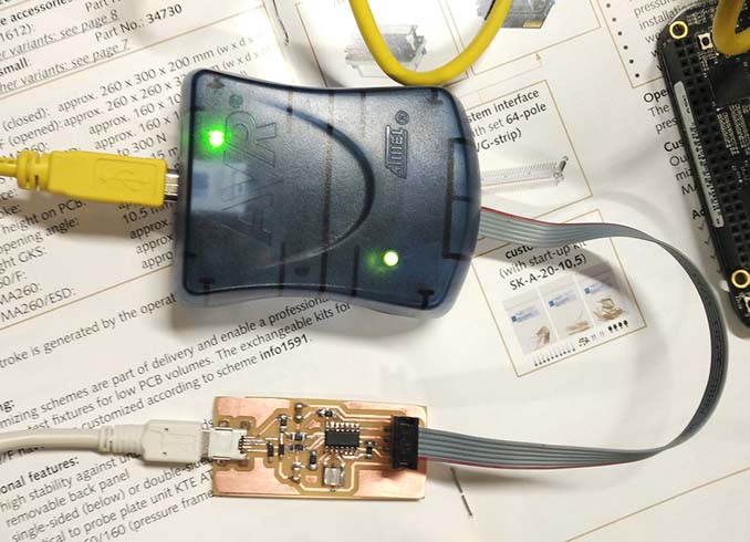
1st step: to set-up my pc (windows 10) to program the FabISP I followed this great tutorial; but to install the AVRISP MKII libusb programmer drivers I needed this software, the solution was found in this forum.
2nd step: connect the fabISP to the usb port and check for smoke! After open the commands prompt and navigate to the folder with the firmware downloaded.
> cd c/fabisp/firmware
Check with AvrDude if my isp was recognized using this command.
> avrdude -c avrisp2 -P usb -p t44 -t
I manually write the FuseBits with the values to use the external 20Mhz resonator, because we found that there is a difference between the Attiny44 and Attiny44A, so the make file not work correctly because reverses the sequence of the fuse.
3rd step: open the Make file and check it; after compile it with this command.
> make hex
4th step: now we can finally flash the firmware using the command:
> make flash
5th step: the final step is to desoldering the R4 jumper 0 Ohm resistor, than connect the fabISP to the computer and check if the device will recognized.
> make flash
Conclusion: After a couple of test I have got a short so now I must debug my fabISP and fix the bug or make another one.
Update: at the end I have made a second one, that are working fine.