Electronic Development
Source filesThe control board will communicate with the Robot through the serial and
will execute the command that the robot will send.
So, in order to have the pellet extruder work I will need some ceramic heater
cartridge to heat the noozle, a thermocouple to control the temperature,
a DC geared motor for the extrusion and a solenoid valve to cool the
extruded material.
Starting from these needs I decided to usa an ATMEGA328P-AU insted of using the
Attiny44 (that we have used for all the exercises), because I will need a lot
of PWM ports and the hardware serial, in order to allow the comunication between
the robot and the control board.
To control the nozzle temperature I will use a thermocouple to allow a very
accurate measurement; so I will use an external module with an AD595 in order
to read the data from the thermocouple type K (in the first version of the board
I used the integrate directly on the board).
To heating the nozzle I use 3 Ceramic heater cartridge, so I will need 3 mosfet
to allow the control of the heating and other two to control the DC geared motr
and the Solenoid valve to cooling the extruded material.
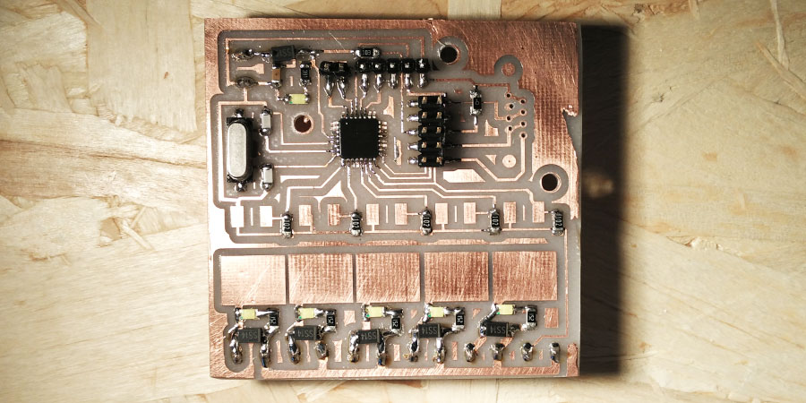
For the assignment of input and output I have designed the first version of
the board v_0.1, that is at the second version the v_0.2
with some improuvement, like some LED that will show when the output are working.
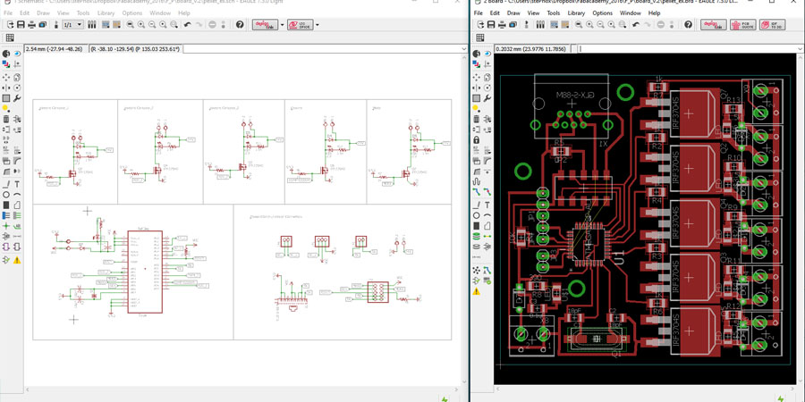
Above the schematics and the board design.
This board was pretty easy to design, the most difficult thing was mill the
PCB and obtain a good result, because the very small space between the pads
of the ATMEGA 328P-AU that is only 0,25mm.
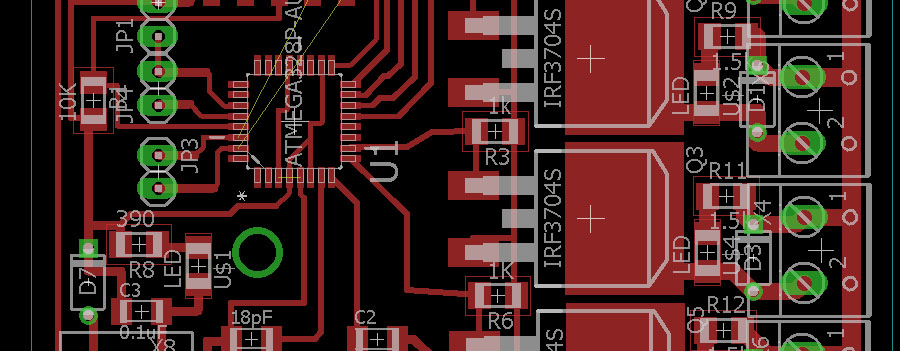
In this board I have used 16mil tracks, but hte tracks near the 328P
are 12mil, and the power tracks that will work at 24V with a lot of current
are 50mil.
On the board I have installed an RJ45 connector, used to connect the board
to the robot main controller where I have installed an RS232 to ttl converter,
so basically the cable have the RX, TX, VCC and GND lines.
I have decided to use this kind of cable because is very easy to find every
where and have a good shielding, this is essential because the main controller
is 10m away from the robot arm.
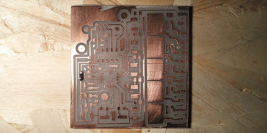
The milling process is the same described in the Electronic Production module.
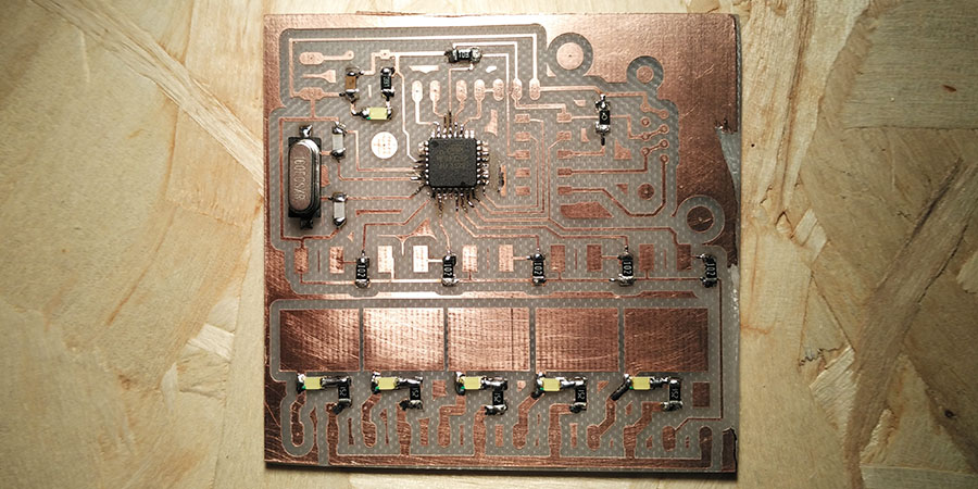
Soldering all the components was not so difficult, except that I haven't paid much attention and I have soldered the micro not in the correct direction; so I lerned that isn't a good idea to solder at deep night.
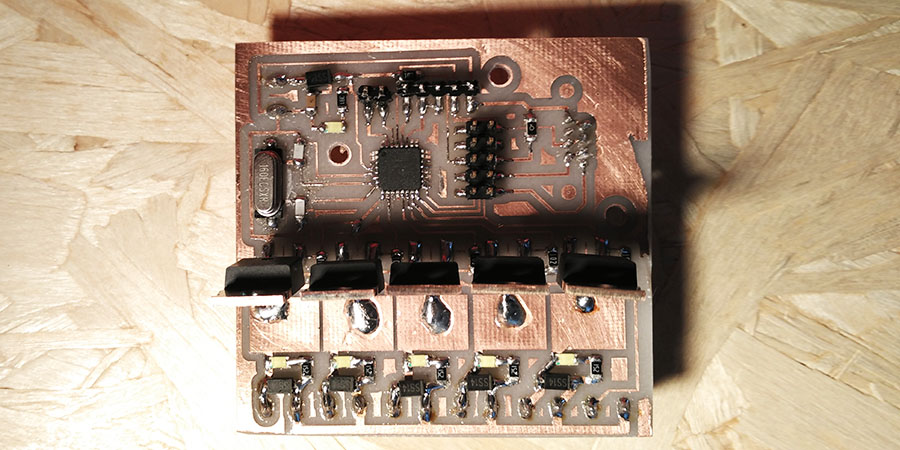
In the schematic I have used SMD mosfet, but after some test I decided to use the classic TO-220 package, because mostly the motor's one become a little bit hot; so in this way I could use a heatsink.

After some test I have decided to use this technique of two Parallel Mosfet on the motor control, because when I use it with very low rpm the mosfet begins to work badly. Now the mosfet works very well, with very low operating temperatures.
Open issues
- add the silk to help assembling and connection
- add a voltage regulator in order to have only the 24V power connection
- check if is possible to use the serial (115200baud) at internal clock 8Mhz