Exercise 12 - Input Devices
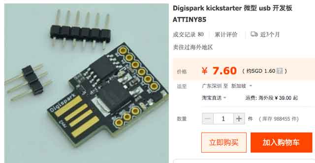
ATtiny 45
ATtiny 45 has 4K flash, 6 I/O's, 256 bytes of RAM and 256 bytes of EEPROM. It has an internal oscillator which runs 8 or 16MHz. ATtiny 45 when compared to an Arduino Uno, it is so much cheaper. It is a suitable choice for small projects.
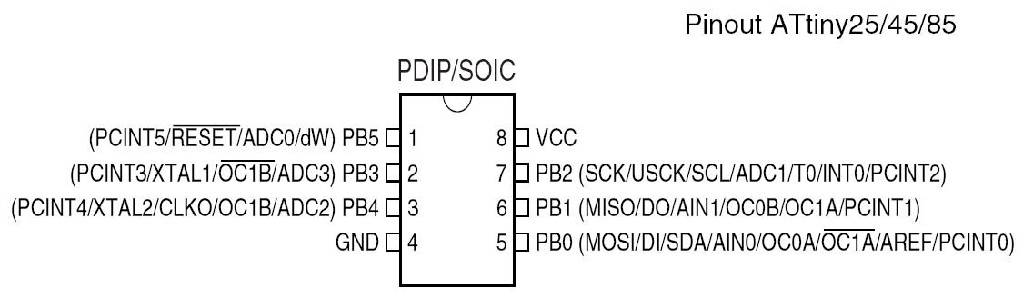
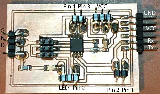
Pin Layout
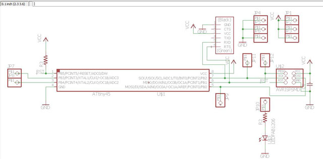
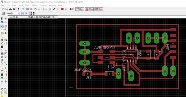
Design of PCB
I used Eagle software to design my pcb. As I do not have enough time, I decided to make the ultimate lazy board. I have included pins so that I can re-use this board to try on different inputs. How to use eagle is already covered in Electronics production. I will not repeat the steps again.
Programming the board
As I am more familiar with Arduino, I will be using arduino as the isp and use Arduino IDE to program the ATtiny. Please refer to embedded programming on using Arduino as ISP.LDR(Photoresistor)
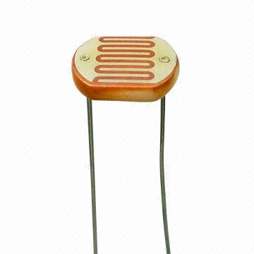
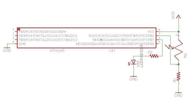
Photo resistor or light dependent resistor, is a light controlled variable resistor, The resistance decreases with incresing incident light intensity. We are going to connect up the circuit as below. I will read in the value of the ldr and program it such that when we cover the ldr, the led will turn on. This is to simulate a night light circuit.
Program code
I am trying to pogram it such that when the surround is bright, the LED is off. When it is dim, it will be on.
const int ledPin = 3; //physical pin 2const int ldr = A2; //physical pin 3
void setup() { // initialize the LED pin as an output:
pinMode(ledPin, OUTPUT);
pinMode(ldr,INPUT);
}
void loop() {
int v = analogRead(ldr);
if(v < 100)
{
digitalWrite(ledPin,HIGH); //Turn on LED
}
else
{
digitalWrite(ledPin,LOW); //Turn off LED
}
}
The Result
When the light is on, the LED is off. When I off the light, the LED turns on.PIR(Passive Infrared)
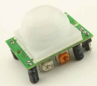
When the two detectors “see” different values, the sensor indicates it as movement of an object, such as a person or an animal.
Sensor need to warm up for 20 to 60 seconds after first applying power to stabilize else sensor output is not reliable.
We are going connect the input pin to pin 0(which is physical pin 5) The Vcc and gnd to the arduino's vcc and gnd.
Program code
int inputPin = 0; //pin 5
int LEDPin = 1; //pin 6
int val = 0;
int pirState = LOW;
void setup()
{
pinMode(LEDPin, OUTPUT);
pinMode(inputPin, INPUT);
}
void loop()
{
val = digitalRead(inputPin);
// read the input pin
if(val ==HIGH)
{
digitalWrite(LEDPin,HIGH);
pirState = HIGH;
}
else
{
digitalWrite(LEDPin,LOW);
pirState= LOW;
}
}
The result
Ultrasonic
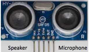
Ultrasonic is a high frequency sound (typically 40KHz is used). A short burst of wave ( often 8 cycles) is sent out by the speaker. The microphone listens for an echo. The time taken is recorded. Using calculation L = C X T/2
L : Length
C: Speed of sound in air (344m/s at 20 degrees celcius)
T : time taken is divided by 2
The distance is determined.
Download
Download NewPing LibraryPut the "NewPing" folder in "libraries\".
In the Arduino IDE, create a new sketch (or open one) and select from the menubar "Sktech->Import Library->NewPing".
Download Putty for serial monitor
Program code
#include <NewPing.h>
#include <SoftwareSerial.h>
#define TRIGGER_PIN 0 // Arduino pin tied to trigger pin on the ultrasonic sensor.
#define ECHO_PIN 4 // Arduino pin tied to echo pin on the ultrasonic sensor.
#define MAX_DISTANCE 200 // Maximum distance we want to ping for (in centimeters). Maximum sensor distance is rated at 400-500cm.
NewPing sonar(TRIGGER_PIN, ECHO_PIN, MAX_DISTANCE);
// NewPing setup of pins and maximum distance.
int ledPin=3;
int rx=2;
int tx=1;
SoftwareSerial mySerial(rx,tx);
void setup() {
mySerial.begin(9600);
pinMode(ledPin,OUTPUT);
pinMode(rx,INPUT);
pinMode(tx,OUTPUT);
}
void loop() {
delay(50); // Wait 50ms between pings (about 20 pings/sec). 29ms should be the shortest delay between pings.
mySerial.print(sonar.ping_cm());
mySerial.println("cm");
if(sonar.ping_cm() <= 15){digitalWrite(ledPin,HIGH);}
else {digitalWrite(ledPin,LOW);}
}
1. Load the sketch
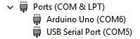
2. Plug in FTDI and check com port for Putty
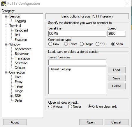
 3. Set up communication for putty
The result
I have modified from the NewPing example program and whenever there is an object that is 15cm or less from the ultrasonic , the LED will light up. The measurement seems quite accurate. It seems that my hp is picking the sound from the ultrasonic. Whenever my hp goes near it, a rattling sound is heard.
My thoughts
I began to appreciate the importance of documentation. I sometimes need to refer my pass documentation because i cannot remember the exact steps,for example, the steps in using the milling machine.
With China offering cheap ATtiny boards, we might not need to fabricate since they are so cheap.
With my lazy board, I will be able to test my laser gun project and evaluate if I need a more powerful processor.
I should have designed my board smaller and the jumper pins in sequence.
Download
ATtiny ldr program
ATtiny pir program
ATtiny ultrasonic program
ATtiny eagle board
ATtiny eagle schematic
Would you like to insert more style/elements?
Check the documentation of Bootstrap here.