Exercise 06 - Electronics Design
Adding LED to hello board
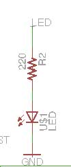
To add an LED to the hello board, we need to include a current limitting resistor to the LED to prevent from blowing. According to Ohms law V=IR. Take for instance, I am using a Red LED with a LED voltage drop of 2V and a forward current of 15mA. My supply if from USB which gives me 5V. I can calculate the value of the resistor.
R = (Power supply voltage - LED volatage drop) / LED current
= (5-3)/(15 X 10 ^-3)
=200.
The closest value is 220ohm.
Adding a switch to hello board
Pull up resistor
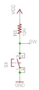
Whenever a microcontroller measures the state of a digital input pin, it can only be high or low. Some external device must be connected to that pin to apply a high or low voltage. If the pin is not driven high or low by an external device or component, it will just be floating in an unknown state. To prevent this unknown state, a pull-up or pull-down resistor will ensure that the pin is either high or low state. In order to connect a switch to hello board, I am using a pull up resistor to the switch.
With the pull-up resistor, The input pin will read a high state when the button is not pressed. When the button is pressed, current flows through the resistor to ground, the input pin will read low. Without the resistor, when we press the button, we are shorting VCC directly to ground. It could cause massive damage to the circuit and power supply.
I have chosen the value of the resistor to be 10K ohm.
Using Eagle to design PCB
Eagle is a PCB CAD software. The limitations of the free version are:-
1. 1 schematic sheet
2. 2 signal layers(top & bottom)
3. Board area limited to 100 x 80mm
4. Limited to email or forum support
5. Use is limited to non-profit applications.
Steps
1. Download Eagle software
2. Copy Fab.lbr into the lib directory in Eagle.
3. Create a new project and add a new schematic.
4. Add components into schematic by using the ADD tool and create connections between them by using the NET tool.
5. Name the nets that need to connect together the same name and label it so that the name appears in the diagram
6. Switch to the board view and position the components.
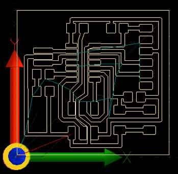
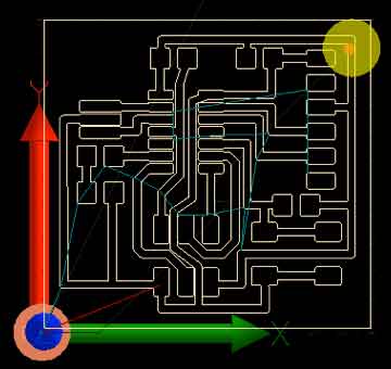
7. Run the Ratsnest command.
8. Use the Route button to manual route the circuit and ripup to remove trace.
9. Run a Design Rule Check and correct any mistakes.
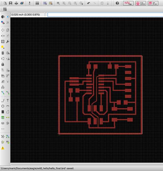
10. If everything is ok, we can mill the board. We are using a PCB2020B CNC router.
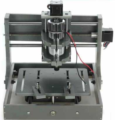
The pcb milling machine that we are using is a CNC 2020B machine. It is an entry level cnc equipment. It is MACH3 compatible system . It has a working area size 200mm(X-axis), 200mm(Y-axis) & 70mm(Z-axis) and equipped with a 300W high speed spindle. The main shaft speed is able to operate from 6000 to 12000rpm/min and the tool diameter range is from 0.3 to 3.175mm. It is powered by 3 stepper motors.
The USB-control board is USBCNC compatible and interfaces between the PC and the Mach-3 controller board. The input for the PCB2020B is a gcode file.
We are currently using a Vbit instead of a mill bit recommended by Neil. This is to cut cost. However, this also create some problems during fabrication because if the the pcb is not completely flat, this will cause the v bit cutting deeper on certain area and this will result in thinner copper threads produced. We hope to convince the instructors to buy the right tool for the right job so that the next batch of students will not face this problem.
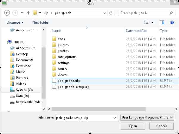
Click File -- Run ULP.
11. Download and select pcb-gcode-setup.ulp
12. Tab on machine and set the units to mm.
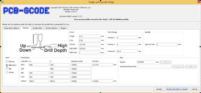
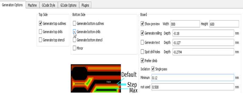
13. Adjust the settings as shown below with the boxes checked.
14. The program will generate a tap file.
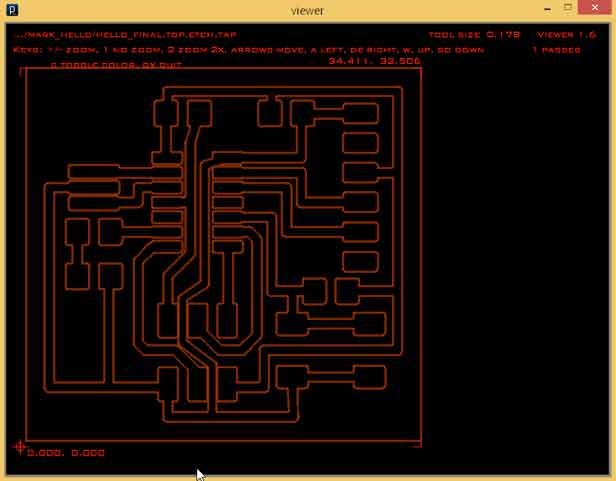
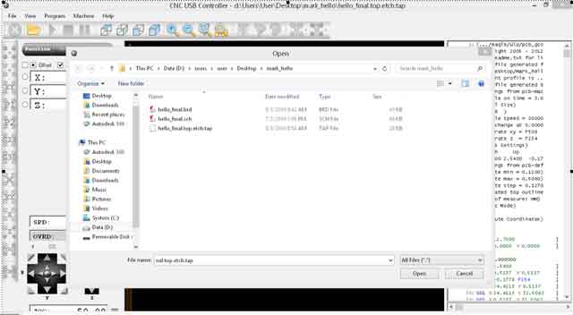
15. Load the file into the CNC program.
16. Calibrate the X,Y and Z position and use paper to determine the depth of cut by testing at least 2 points.
 |
 |
|---|
17. Press the start button to begin milling.
My finished product
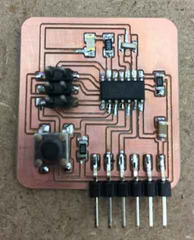
This is my second time soldering smt. I think I am getting better now.
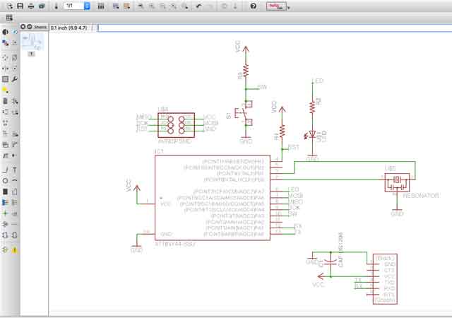
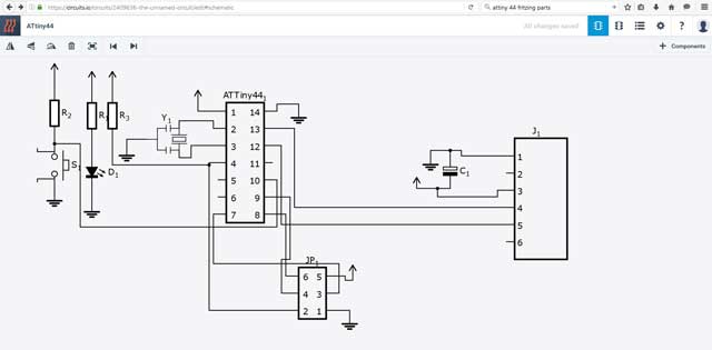
My schematic.
Types of PCB
There are 6 different types of materials to make pcbs. FR1 to 4, CEM-1 and CEM-3.
Fr1 is basically the same as FR2 but FR1 has a higher Glass transition temperature (Tg) of 130 degrees Celsius instead of 105 degree Celcius for FR2. A high Tg is important to guard against barrel cracking and pad fracture during the soldering .
FR3 is like FR2. The difference is that FR3 uses epoxy resin binder instead of phenolic resin.
The circuit board that we can using, is a single sided FR4 . (FR = Flame Retardent) It is is a glass fiber epoxy laminate. It is the most commonly used PCB material. It uses 8 layers of fiber glass materials. It is widely used in PCBs because it is good to make single to multi layer pcb.
CEM-1 (Composie Epoxy Material) is a paper-based laminate with one layer of woven glass fabric. It is not suitable for Plated Through Hole, same as FR1-3. CEM-1 can only be used for one-layer PCB.
CEM-3 is like FR4. Instead of woven glass fabric a "flies" type is used. CEM-3 has a milky white color and is very smooth. It is a complete replacement of FR-4.
Autodesk Circuits
Autodesk created a new online PCB software. To create the schematic diagram was quite easy as all the things are drag and drop. To find the correct footprint is the problem. I was not able to find the smt version of ATtiny 44. As I did not have time to design my own, I contiunued to explore the software.
The software is very unstable. It froze for no reasons. I have to relauch the software to continue designing.
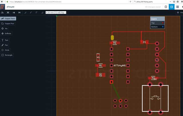
All of a sudden, the copper thread disappeared
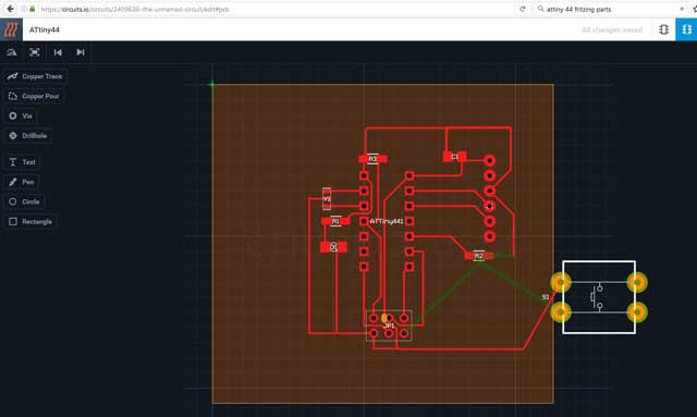
When I was rotating the component, it froze again!
My thoughts
The experience of using Autodesk Circuits was terrible. It froze at least 6 times. Unless Autodesk comes out a more stable version, I will continue to use Eagle.
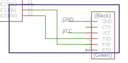
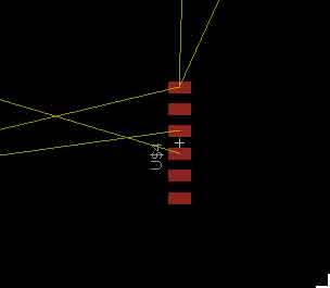
I faced some strange problem with Eagle. Sometimes what you see is not what you get. The net is not properly snapped to the component. In schematic view, there are 4 connections to FTDI-SMT-header. In the board view however, there are only 3. I managed to solve by removing the route from pin 12 and 13 and use labels instead. For single PCB, I prefer to do manual route instead of using auto route.
 |
 |
|---|
References:-
1. Eagle tutorial by element14.
2. Sparkfun eagle tutorial.
3. Arduino blink.
4. Arduino switch.
Would you like to insert more style/elements?
Check the documentation of Bootstrap here.