Exercise 08 - Embedded Programming
Datasheet of ATtiny 44
Pin configuration of ATtiny 44
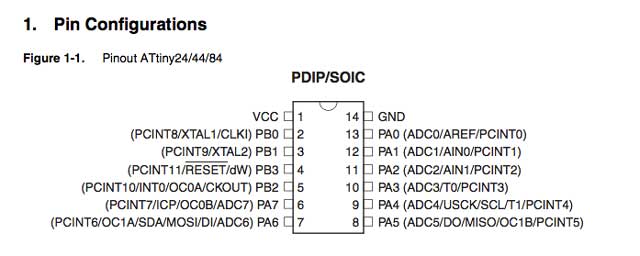
From the reading of the datasheet, we can find out many useful information like it is an 8 bit microcontroller with internal clock 8Mhz, the program memory size 4k, 256B EEprom, 256B SRAM. If our program is too big for the memory and that is when we need to look for alternative chip. The number of I/Os for this chip is 12. The operating volatge is from 2.7V to 5.5V (helpful so that we do not damage the chip). The maximum clock frequency is 20Mhz. The pin out scheme we enable to design and connect our circuit correctly.
| Data Bus Width: | 8 bit | |
| Maximum Clock Frequency: | 20 MHz | |
| Program Memory Size: | 4 kB | |
| Data RAM Size: | 256 B | |
| ADC Resolution: | 10 bit | |
| Operating Supply Voltage: | 2.7 V to 5.5 V | |
| Maximum Operating Temperature: | + 85 C | |
| Processor Series: | tinyAVR | |
| Packaging: | Bulk | |
| Brand: | Atmel | |
| Data RAM Type: | SRAM | |
| Data ROM Size: | 256 B | |
| Data ROM Type: | EEPROM | |
| Interface Type: | SPI, USI | |
| Minimum Operating Temperature: | - 40 C | |
| Number of ADC Channels: | 20 | |
| Number of I/Os: | 12 I/O | |
| Number of Timers/Counters: | 2 Timer | |
| Product: | MCU | |
| Program Memory Type: | Flash |
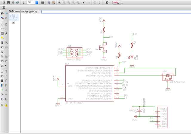
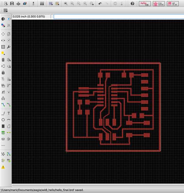
If you look at the schematic, you will notice that we wired a pull up resistor to the switch. With a pull up resistor, the input pin will read a high when the button is not pressed. The input pin will be close to Vcc. When we pressed the switch, the input pin will be connected to ground.
The connection of LED is PA7 and switch is PA3.
Why I used Arduino as ISP instead of fabisp?
There is this misconception that I had that fabisp will not work with Arduino IDE but can only use avrdude. The first problem that I faced was where to find the windows driver of fabisp. i could not find it. That was why I used Arduino as ISP because i am not familiar with avrdude and C programming. I have since realised that I can download the driver from here. i then set the programmer as USBtinyISP and I need to connect the device that I want to program to FTDI and connect back to the computer so that the com port can be found.
Why Arduino UNO as ISP?
Using Arduino ISP as an AVR In-System-Programmer will not only allow us to upload sketches directly but also to burn the bootloader to an AVR(e.g. the ATmega168 or ATmega328 used in Arduino). As I have some knowledge of basic Arduino and we own many Arduino UNO in the library, I prefer to use Arduino as the isp.
Using Arduino UNO as ISP
Go to File---Examples---ArduinoISP---ArduinoiSP. Upload the sketch to Uno. Under File preferences, look for Additional Boards Manager URLs and add in https://raw.githubusercontent.com/damellis/attiny/ide-1.6.x-boards-manager/package_damellis_attiny_index.json to it. This will install attiny support in Arduino. The detail steps can be found at highlowtech.org/?p=1695
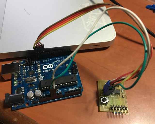
Connect as shown below
| UNO | Hello |
|---|---|
| 10 | RST |
| 11 | MOSI |
| 12 | MISO |
| 13 | SCK |
| VCC | VCC |
| GND | GND |
Burn bootloader
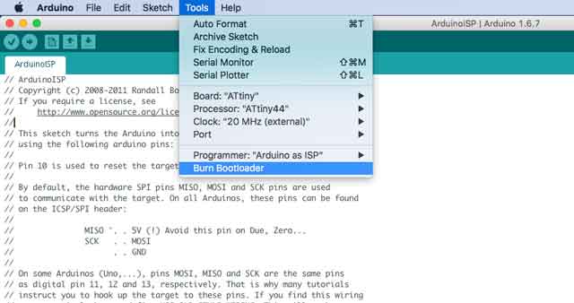
Set the board to ATtiny, processor Attiny 44, clock 20MHz and the correct com port, click Burn Bootloader.
Test by loading the file -- examples -- basic -- blink. The sample program uses pin 13. I changed it to pin 7.
void setup() {
// initialize digital pin 7 as an output.
pinMode(7, OUTPUT);
}
// the loop function runs over and over again forever
void loop() {
digitalWrite(7, HIGH); // turn the LED on (HIGH is the voltage level)
delay(1000); // wait for a second
digitalWrite(7, LOW); // turn the LED off by making the voltage LOW
delay(1000); // wait for a second
}
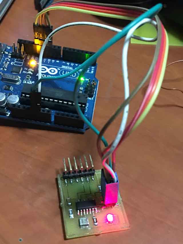
Oops! Didn't realised that I uploaded the wrong pictures. This pcb above is a test on my friend's board. He suspected that his chip is faulty. We have been doing our testing together and have been swopping boards to verify hardware and software programming. We used the same camera too. I am more familar to programming than my colleagues. I helped to test their pcb boards if they cannot find the problem.
It is inevitable that people will suspect that I used someone's board and pretend that it was mind. It was an honest mistake on my part as most of our pcb boards look similiar with one button and one LED and the other problem is that I did not document as I go along. I only document after the process. I was in a hurry to complete my documentation within the same week that I did not realize my mistake until it was pointed out by someone. I began to appreciate now why Neil insisted that we document as we go along rather than do it later.
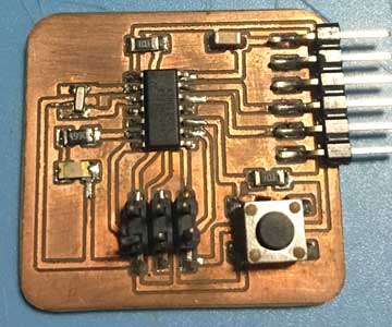
The correct picture is below. This is the same board that I used in the youtube video seen in the results below. If you have seen in my week 6, you would have noticed that my pcb has rounded corners. I did it all by myself.
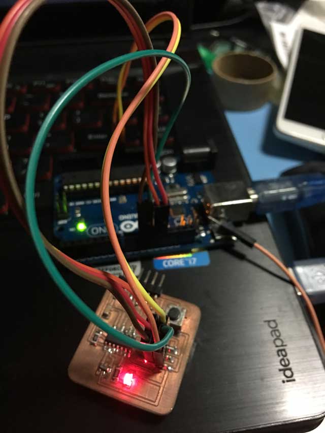
The board being programmed is the same as what I created created in week 6. It is just a simple circuit and I am familiar with Arduino programming, I am sorry for the confusion that I caused. If you checked the youtube video, you will see that I used the same board below.
 |
 |
|---|
In order to test the button and serial communication, I modified the example button sketch to test button, LED and serial communications. I will be using software serial library on an ATtiny to send serial via FTDI over USB for communication to computer.
1. When the button is pressed, a message( LED is on when the switch is pressed) will be sent to the computer via the usb cable and display in the putty software.
2. When p is pressed in putty, the LED will be ON. A message hello board received command to ON LED.
3. When any key from the keyboard is pressed, the LED goes off.
#include <SoftwareSerial.h>
// constants won't change. They're used here to
// set pin numbers:
const int rx=1;
const int tx=0;
const int buttonPin = 3; // the number of the pushbutton pin
const int ledPin = 7; // the number of the LED pin
SoftwareSerial mySerial(rx,tx);
// variables will change:
int buttonState = 0; // variable for reading the pushbutton status
int state;
void setup() {
mySerial.begin(9600);
mySerial.flush();
// initialize the LED pin as an output:
pinMode(ledPin, OUTPUT);
// initialize the pushbutton pin as an input:
pinMode(buttonPin, INPUT);
}
void loop() {
while (mySerial.available() > 0){
state = mySerial.read();
}
if (state == 'p')
{ digitalWrite(ledPin, HIGH);
mySerial.print("hello board received command to on LED.");
delay(1000);}
else
{ digitalWrite(ledPin, LOW);
// read the state of the pushbutton value:
buttonState = digitalRead(buttonPin);
// check if the pushbutton is pressed.
// if it is, the buttonState is HIGH:
if (buttonState == HIGH) {
// turn LED on:
digitalWrite(ledPin, LOW);
} if (buttonState == LOW) {
// turn LED off:
digitalWrite(ledPin, HIGH);
mySerial.print("LED is ON when the switch is pressed!");
}
}
Result
Watch the video
My Thoughts
I find using Arduino easier that coding in C and use avrdude and Make file. It will take me at least a few weeks to learn C and code in hex. There is a disadvantage to use Arduino IDE as the progrom tends to be bigger in size due to the importing of libraries and bootloader.References
1. http://funduino.blogspot.sg/2012/02/attiny45-software-serial.html
Would you like to insert more style/elements?
Check the documentation of Bootstrap here.