Output Devices
Assignment
- Add an output device to a microcontroller board you've designed
- Program it to do something
Output testing in Arduino
For this week I was not sure what I wanted to do so I decided not to jump into making something. I wanted to do some test with photoresistors in Arduino and hopefully it would give me ideas for this week project.
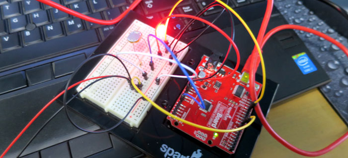
I found this PHYSICS LIGHT ARDUINO LESSON on the web. I used the Spark Fun Arduino kit and plugged all the wires and components.
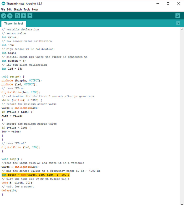
I changed the "int pich" high and low value and that gave me a different sound from the photoresistor. I also changed the "tone(8, pitch, 20)" the pitch that was coming from pin "8" to the buzzer.
Here is a short video with this Photoresistor/ Arduino Theremin sound. The sound from the buzzer is very limited so it´s not similar to the sound the guitar mill make, just a small test.
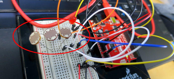
I tried to add three Photoresistors to the same pin and it worked but the sound went crazy. What I also found out is that if I daisy chain the photoresistors the signal became weaker. It’s now clear to me if I like to add more photoresistors to the party I will need to separate them, not have the same analog input.
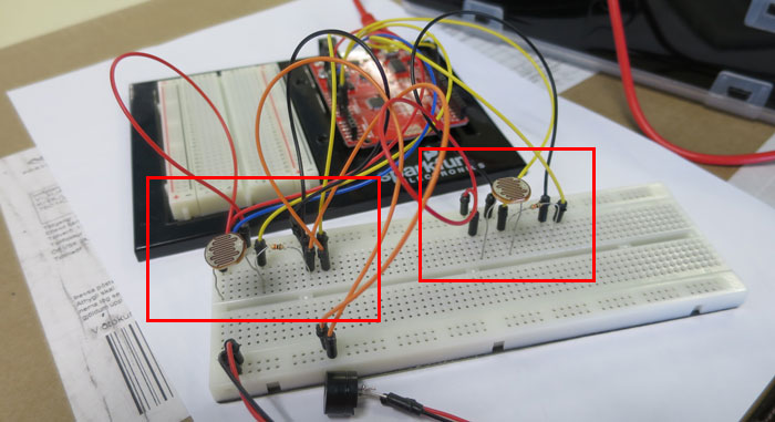
I also realized I needed to make the code simpler so I found a new Arduino Theremin drawing without a LED. I tested that drawing with one photoresistor and it worked. I tried to let Arduino read both photoresistors work but could just let it read one. I decided to rethink it and wire it up again using two bread boards.
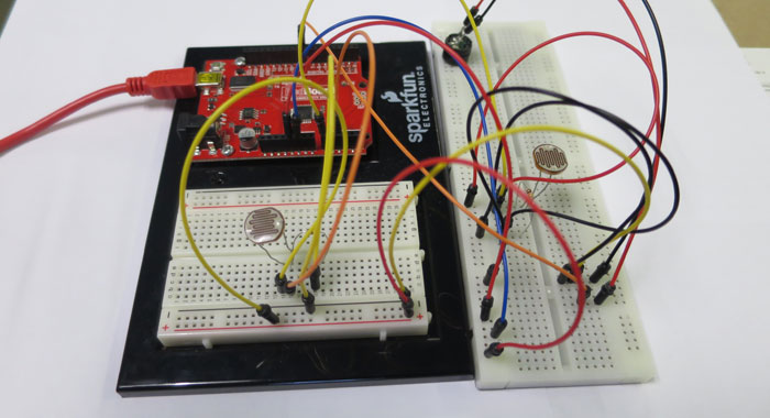
After wiring I tested each photoresistor and they both worked individually.
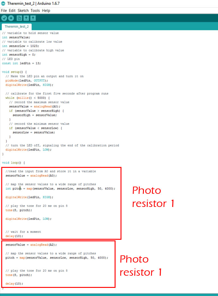
Then I change the code so Arduino would read both analog pins A0 and >A2. Regarding Int = Map Pitch () I had to delete Int when it appeared in the code after analogRead A2 because it was already defined above.
TO BE CONTINUED...
Output Device Assignment - Improve Photo Darlington board
After a brief talk to my instructor I decided to make a new out-put version of my Photo Darlington Board (Week 11). I was going to add LCD Screen to it and let it read information from one or all Phototransistors. I would need more pins then the ATtiny 45 could give me so I went for Mr. Big the ATMega 328p microcontroller.
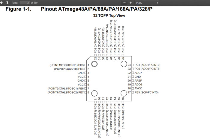
I needed to take a look at the pins configuration before I started to wire the board. Mosi is pin 15 and Miso pin 16. Pin 22 - 28 has ADC configuration for my 3 Phototransistors. Pins 9-15 I connected to the header for the LCD screen and so on.
In my Fab Library (Eagle) I could not find a 2x5 pin header so I added 2x2 pin and a 2x3 pin header. I placed them side by side and later on connected as a 2x5 pin header.
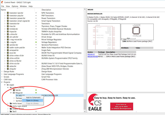
Since ATMega328p microcontroller was not in the Fab library I needed to copy it from Atmel.lbr. The name of the file I copied was Mega8. I made a new library in my custom library and named it Mega.lbr. The reason I needed to copy this file to new library had a reason, I needed to change the footprint. It´s not possible to change the footprints in the original Eagle libraries. ATMega microcontroller is very small and it was too little space between its footprints. The 1/64 inch milling bit could not mill between them as it was set in Atmel library.
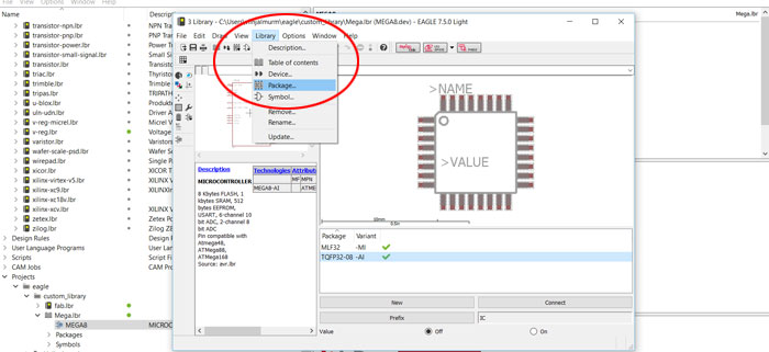
I double clicked on MEGA8 library file in my custom library and then a new window appears. In this new window I can change library files. I clicked on Library/ Package then a Edit window appeared.
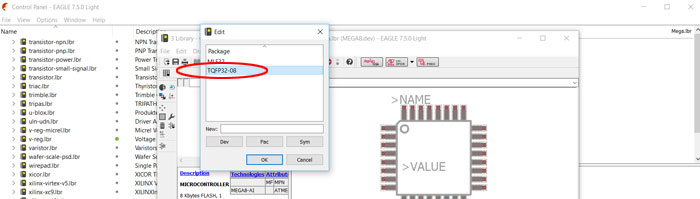
In this Edit window I selected TQFP32-08, that is the footprint I was going to change.
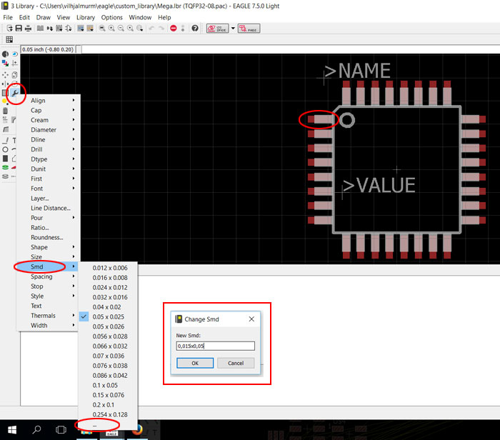
To change the size of the footprint I needed to click, on "Change" and select "Smd" and then select the 3 dots "..." below all the numbers. Then a small "Change Smd" window appeared. The size of each footprint was 0,022x0,05. I changed it to 0.015x0,05. I needed to reverse the numbers for the top and the bottom footprints 0,05x0.015. On this picture I had already changed the size of every footprint and you can see each footprint is smaller than the pins coming out of the microcontroller.
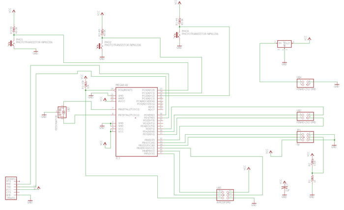
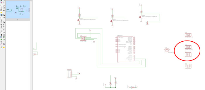
It took me quite some time to connect everything and figure out the function of each connection. This is not the final schematic because later on I added some jumpers.
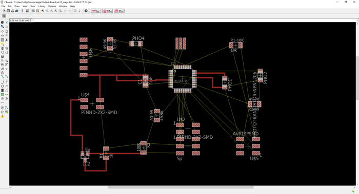
I knew it was not going to be easy to make the traces, way too many lines crossing each other.
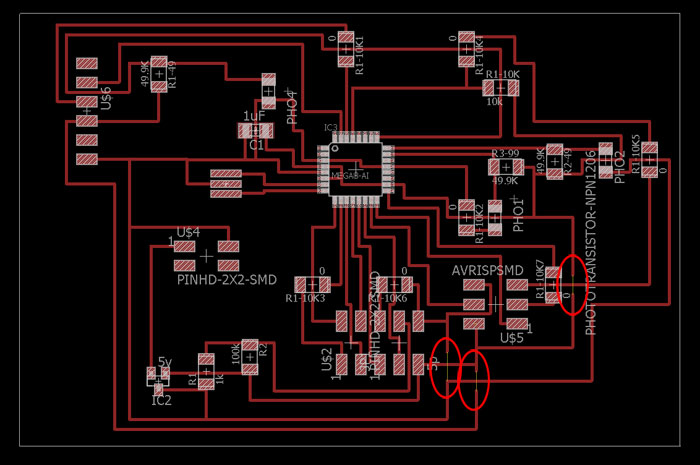
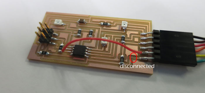
After few hours of work I finally could see the light, but I had trouble finishing it. I had 3 traces that I could not close. Soon as I added a jumper to those traces something else changed. In the end I decided to add the 3 last footprints in Photo Shop, which I did with good success. (Later in the process I learned how to fix that problem in the schematic, let jumper connection be linked all the way with a wire command. Plus change pins connections if possible so I don´t need as many jumpers).
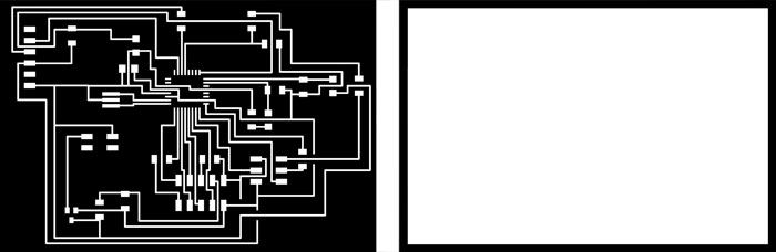
These are the traces and the cut PNG file for the Modula milling machine. When I was milling the board I found out that all traces to the microcontroller footprint was too thick. I needed to narrow them to 0,015 inch. To make it faster I used Photo Shop. I ran the trace file again in same position and it finished milling the board beautifully.
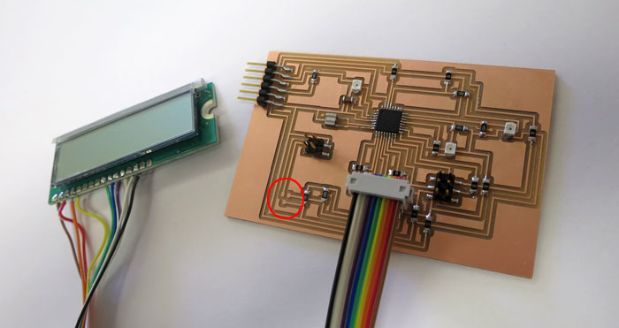
After milling I gathered all the components and soldered the board. I also soldered all wires to the LCD screen and the 2x5 pin header. I waited to solder the voltage regulator because it´s not good powering the board with battery at the same time it gets power from the FTDI cable.
Programming the board

To be able to program the ATMega 328 microcontroller with Arduino I needed a Bootloader. My instructor wrote one for me and that would set the fuses for the 20 MHz clock.
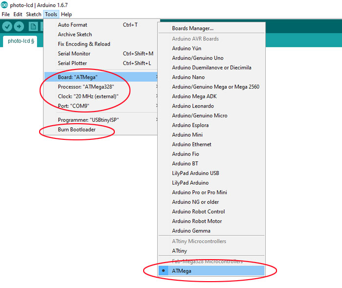
When the settings was ready for the ATMega I could select it in Arduino software (see picture). I connected the board with FTDI cable and the FabISP and clicked on "File/Burn Bootlaoder"
. After that the chip was ready to be programmed.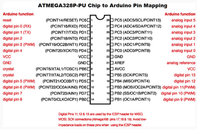
Because I was programming with Arduino I needed to get me a pin mapping for the ATMega 328 chip.
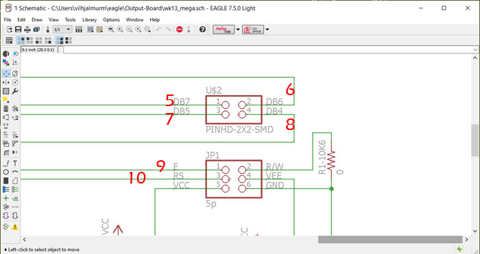
This is the LCD Pin settings that I needed to configure in Arduino. I did not have to worry about pins that are connected to VCC and GND.
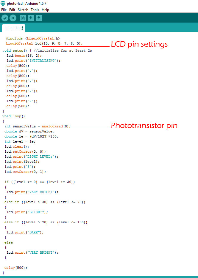
This is the sketch that I am going to use to perform an out-put. It includes a LiquidCrystal library and it reads one analog pin (0) with a phototransistor. What this sketch does is to measure the ambient light level using a phototransistor and display it on the 16X2 LCD. Also show whether it's very bright, bright or dark. It measures the light level in %. Out of a total of 1023 integers, 0 represents 0% and 1023 represents 100%.

I could program the board but the display only showed black boxes, no data at all. I went through the pin configuration, inspected the soldering, the traces and all wire connections both on board and LCD screen. NOTHING WORKED. I decided to mill out a new board, but first I made some modification on it.
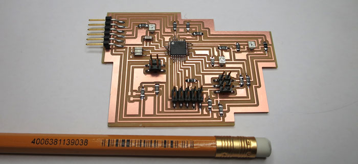
This is the new board. I changed the size from the old one and removed one jumper, plus some other small trace modification. I burned the Bootlaoder and programed the board with success but to my disappointment the same problem occurred, no data on the display just black boxes. Next move was to solder wire to a new display and see if that was the problem. When that was ready I connected the board to FabISP and FTDI cable, BINGO it worked! The display was damaged.
Related links
Multiple Photoresistor Problem ArduinoActivated Object in Art and Technology Studies
Arduino HW2-part 1 (led’s controlled by photocell)
All About Light Sensors
Engbedded Atmel AVR Fuse Calculator
Autodesk Theremin circuits
How to use an LCD disply
How to Control LCD Displays - Arduino Tutorial