Assignment 8
Задание 8
In which I find flaws in my pcb design but make a program anyway
В которой я нахожу ошибку в дизайне платы но всё равно программирую её
Reading data sheet for ATtiny44 and finding an error
Читаю даташит для микроконтроконтроллера и нахожу ошибку
Reading data sheet is the worst. The dullest thing I've ever done. Though, there's one main thing you can get from it - names and purpose of pins of controller. And that lead me to a thought...
Quick reminder: in assignment 6 (pre-evaluation edition, press the button there to see my struggles) I redesigned hello.ftdi.44.echo board and added a button and an RGB led to it
I totally messed up with pins! Damn it! I've sent two out of three outputs of led to the GND. (that's also the reason why I had to replace nice smd led to lame regular led). Also I haven't add a resistor before the diode so it'll live shorter and also connected the led directly to the button which doesn't allow led to glow while the button is not pressed. Well, I'll make a lesson out of it.
Moral: read data sheets before designing your pcb!
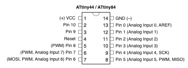
Pins of ATtiny44
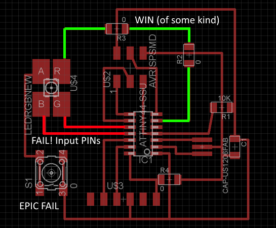
Flaws of my board
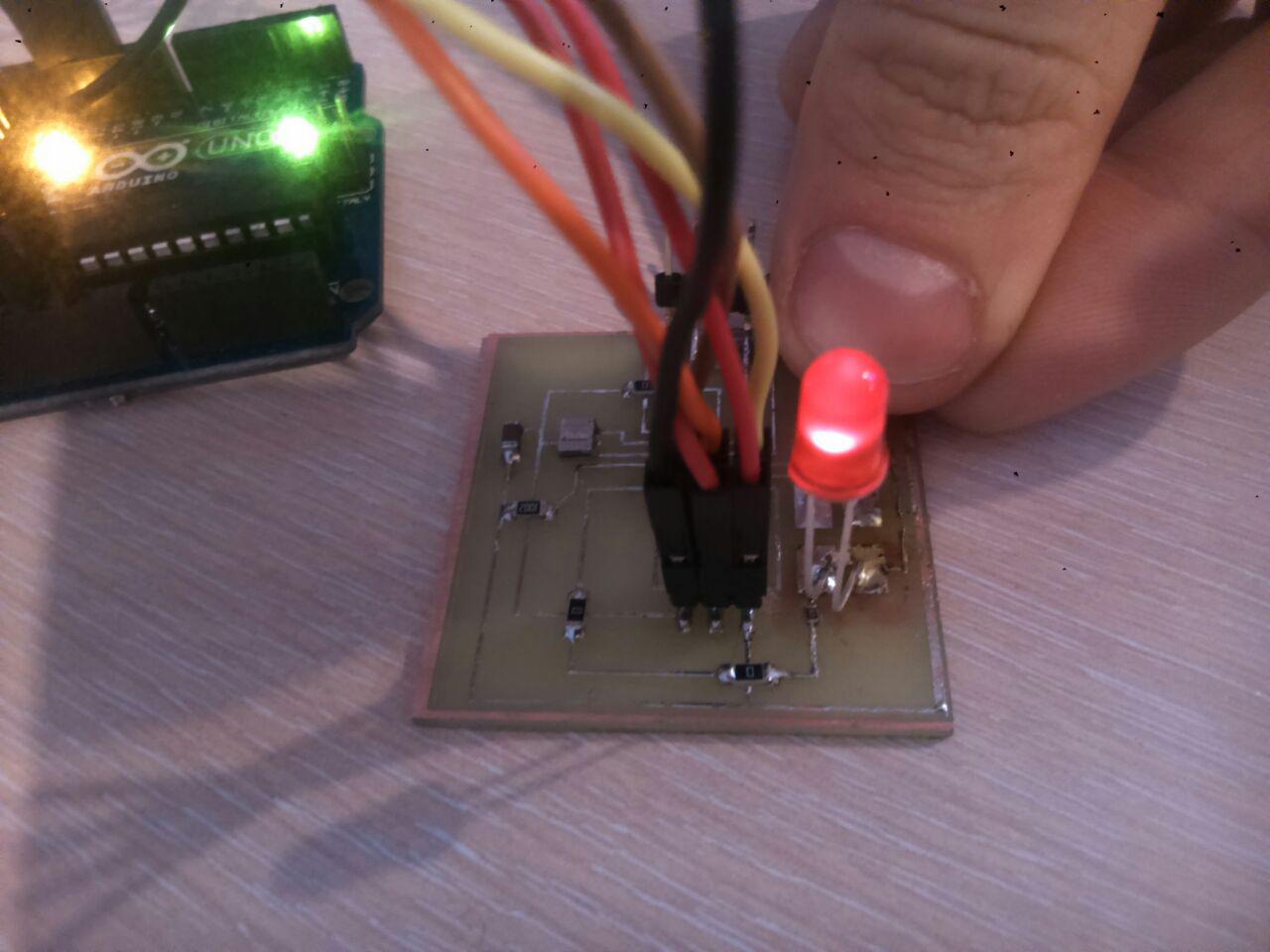
Connecting pcb to arduino Uno and programming it
Соединяем плату с ардуино и программируем
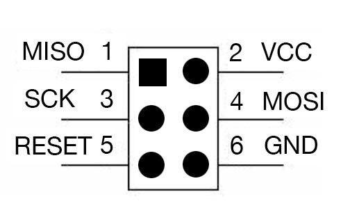
Using pinout, connect pcb to adruino like this:
- Arduino Pin 13 ---> SCK
- Arduino Pin 12 ---> MISO
- Arduino Pin 11 ---> MOSI
- Arduino Pin 10 ---> RESET
- Arduino 5V ---> VCC
- Arduino Ground ---> GND
Then, follow this steps
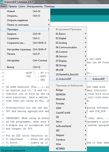
- Run ArduinoISP sketch from "Examples" sketchbook.
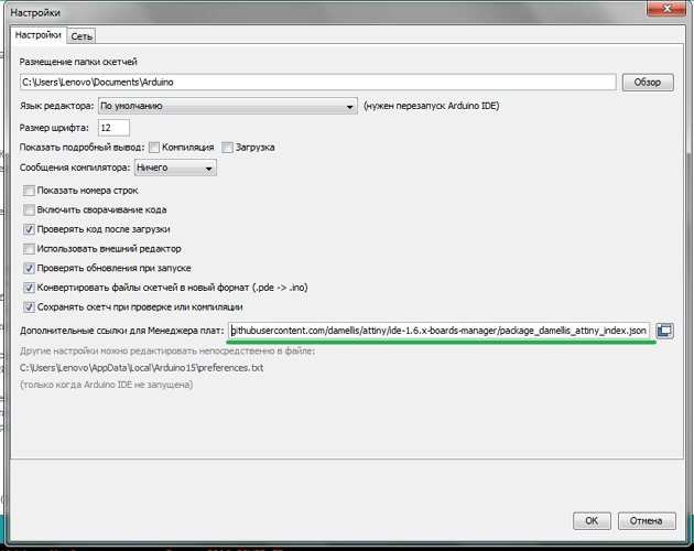
- Copy
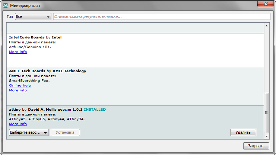
https://raw.githubusercontent.com/damellis/attiny/ide-1.6.x-boards-manager/package_damellis_attiny_index.jsonand paste it into additional board manager and apply settings - Install ATtiny board library in board manager
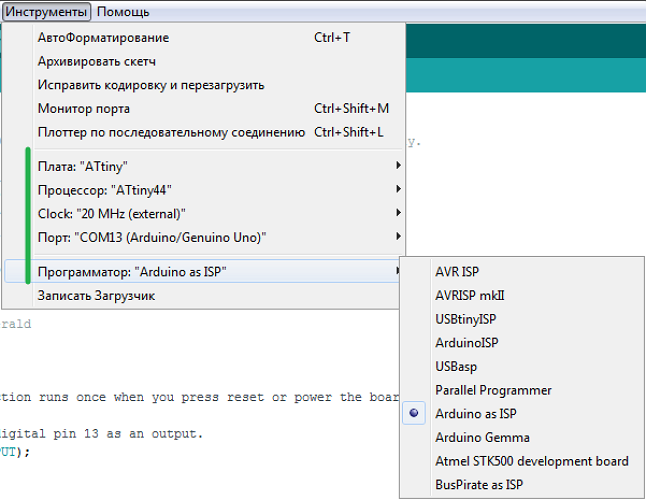
- Set board preferences and programmer
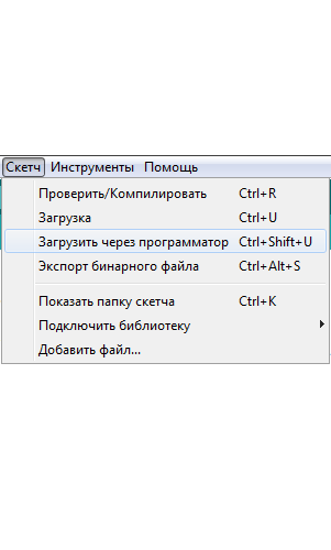
- Run your custom sketch through programmer