
Project Timeline
-
Electronics Design
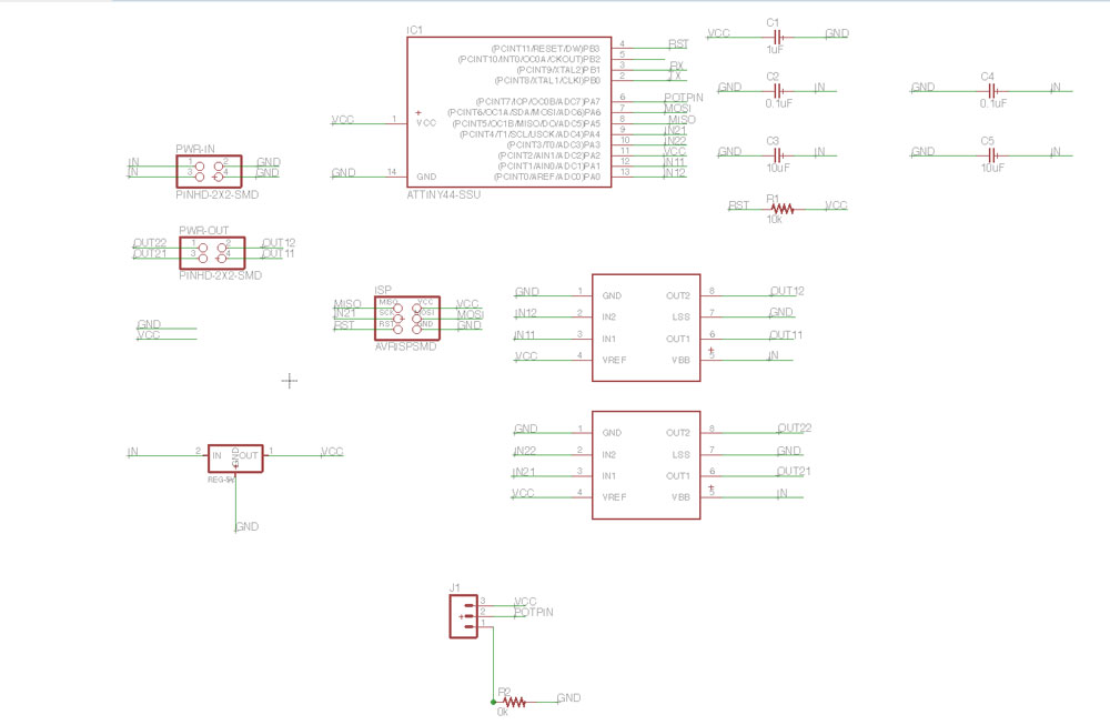
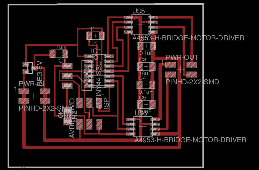
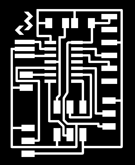
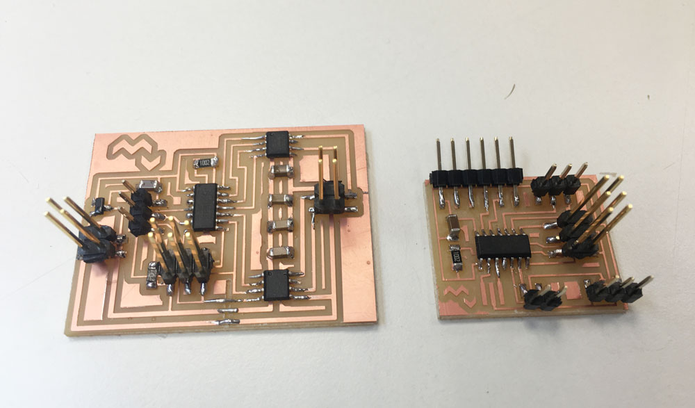
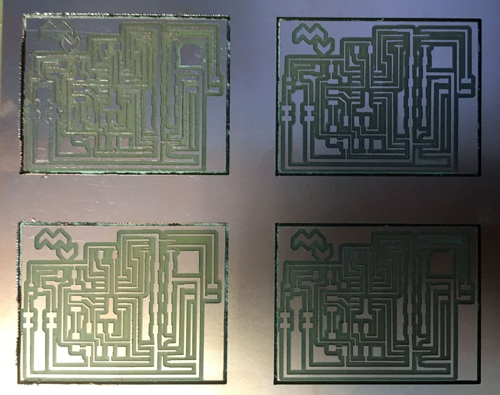
31 May 2016Today I have finished the Eagle Design for the potentiometer + bipolar motor boards. I will mill 5 of those.
And the potentiometer + LED module, also with an Attiny44 and optional crystal.
Because I will use an external light source, not a common LED, I put a 2 pad header, one pin to GND and the other one to PA7, pin that allows PWM (Pulse Width Modulation), to be able to dimm the light. I added an extra potentiometer for that.
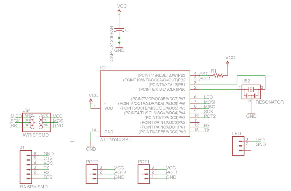
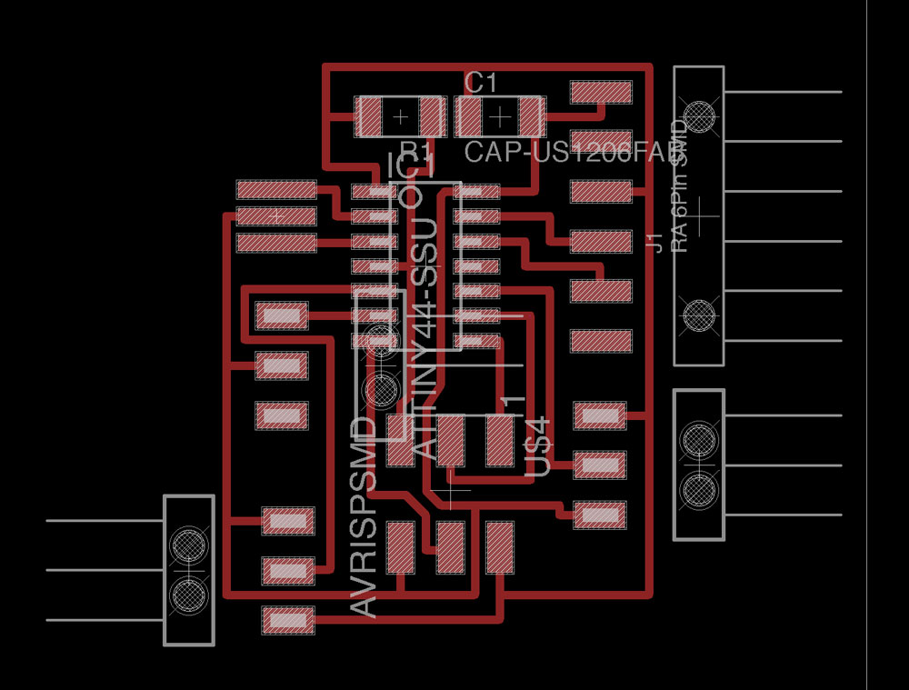
**Update. As I found on 4nd June, one of the potentiometers (PB2) should be connected to an analog pin.
-
Interface Programming
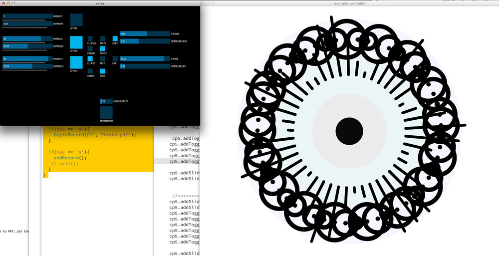
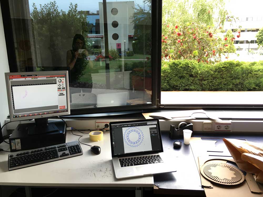
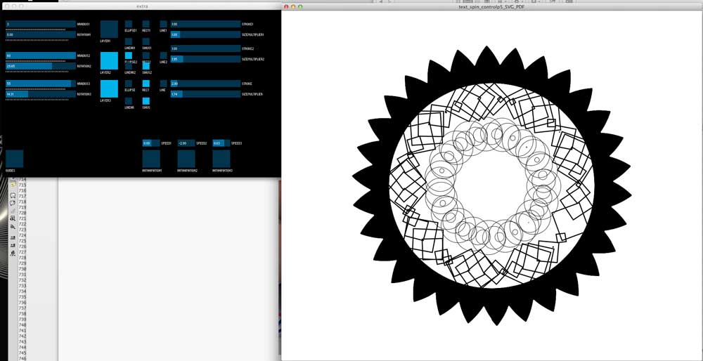
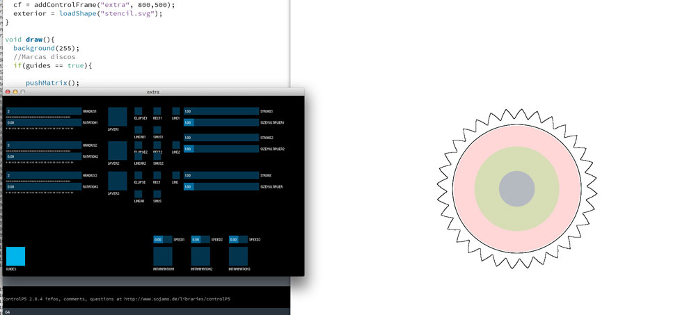
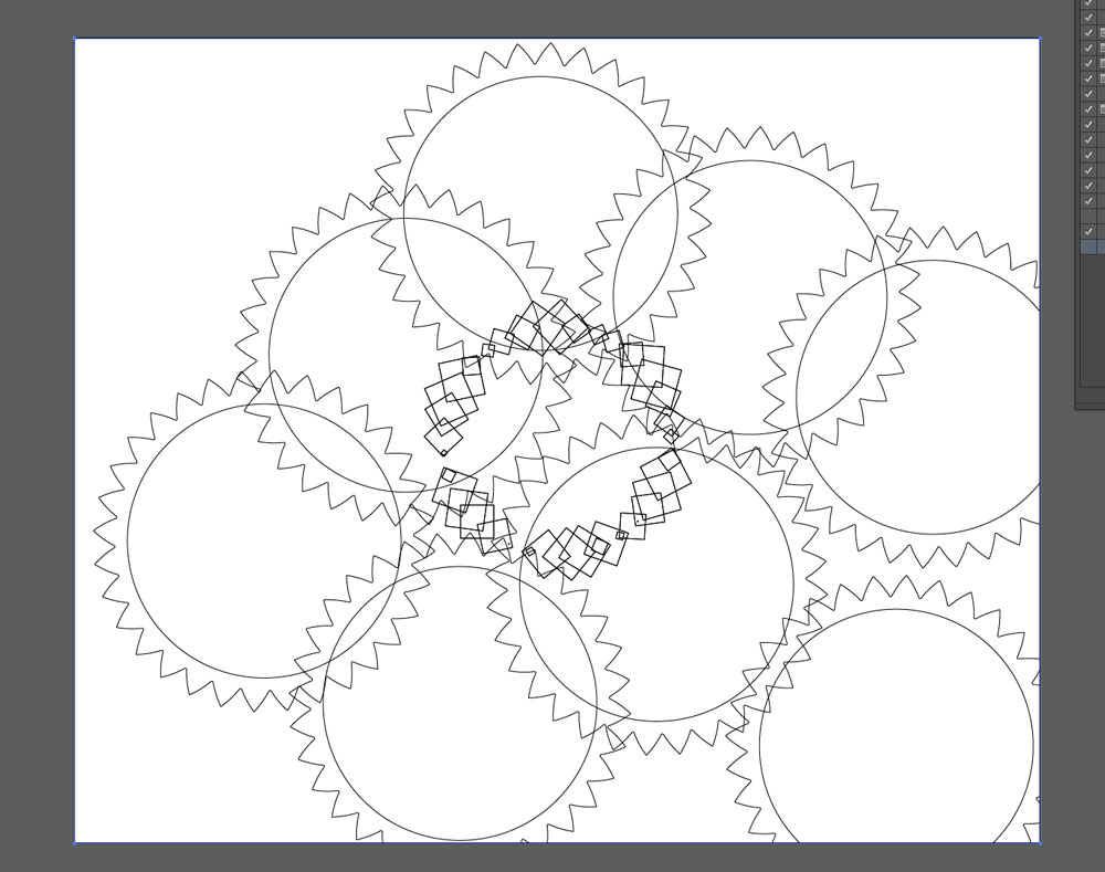
As my "classic" design skills are not the best, I suddenly got an idea; code a Processing application to draw the rotating items and test the "animation" generated by the movement. From Processing I can export an editable PDF file and send it to the Laser Cutter.
I also started a GUI to control the parameters of each layer. I´m starting with 3 possible levels.

-
Electronics Production
June 2, 2016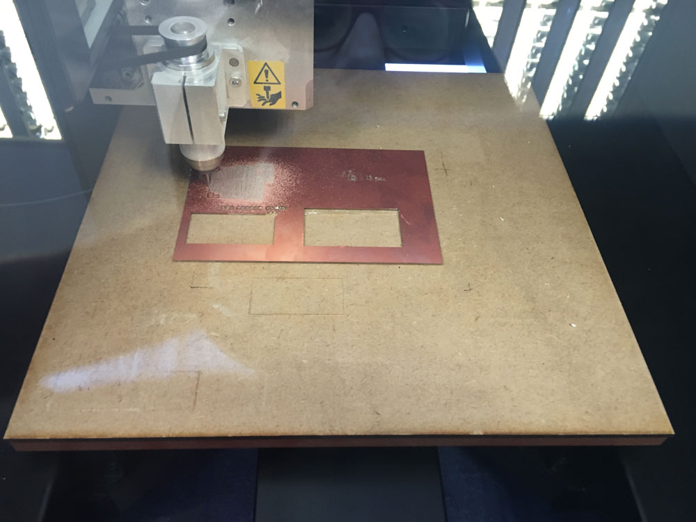
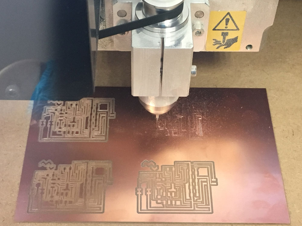
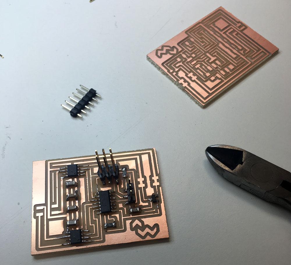
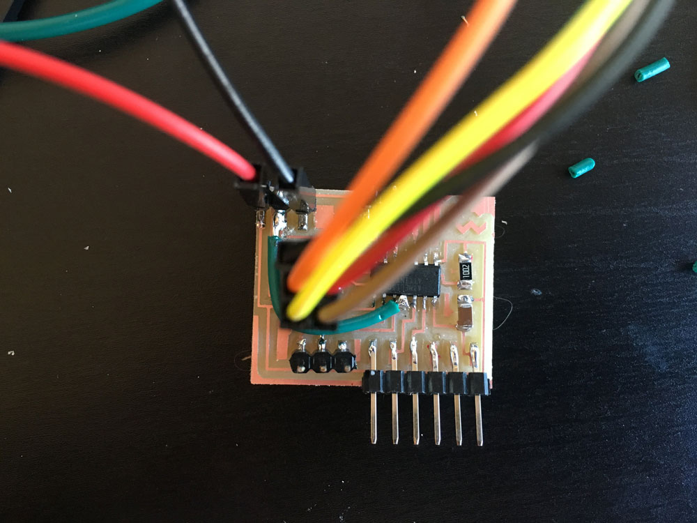
With my already designed boards, I started to mill the 2Pot + LED one and one of the POT + Motor to check if everything is working, and then, fabricate the 4 extra motor ones.
Yes, I made a mistake and launched the cut routine of the LED board (small) to the motor one, but i could stop it in time and fix it :)
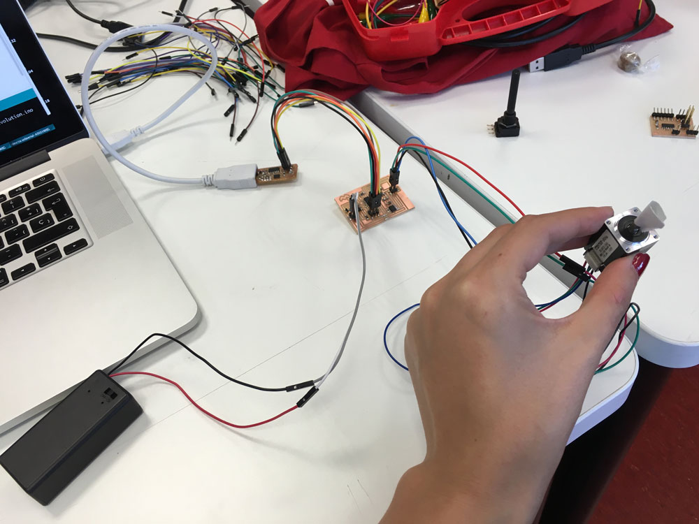
Time to test if they work:
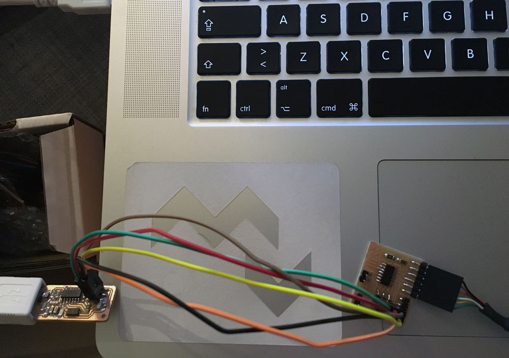
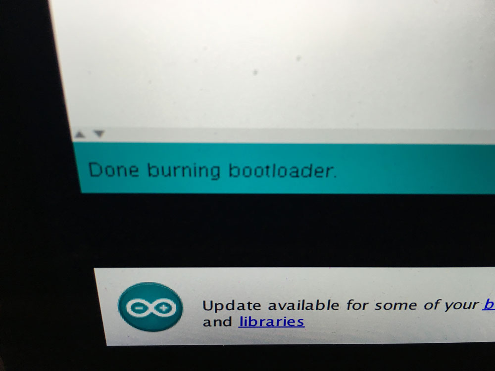
Sucessful bootloader burning with Arduino IDE! They are alive, so I can continue and fabricate the remaining ones.
-
1st code test & Electronics Production
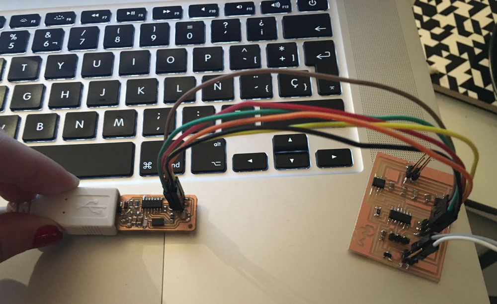
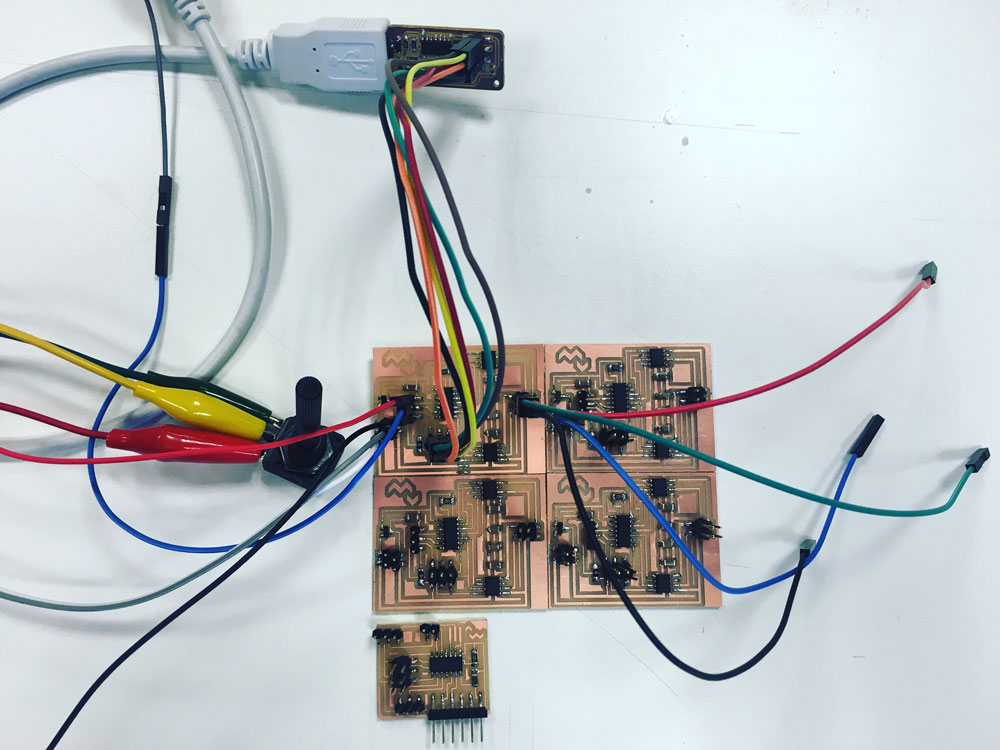
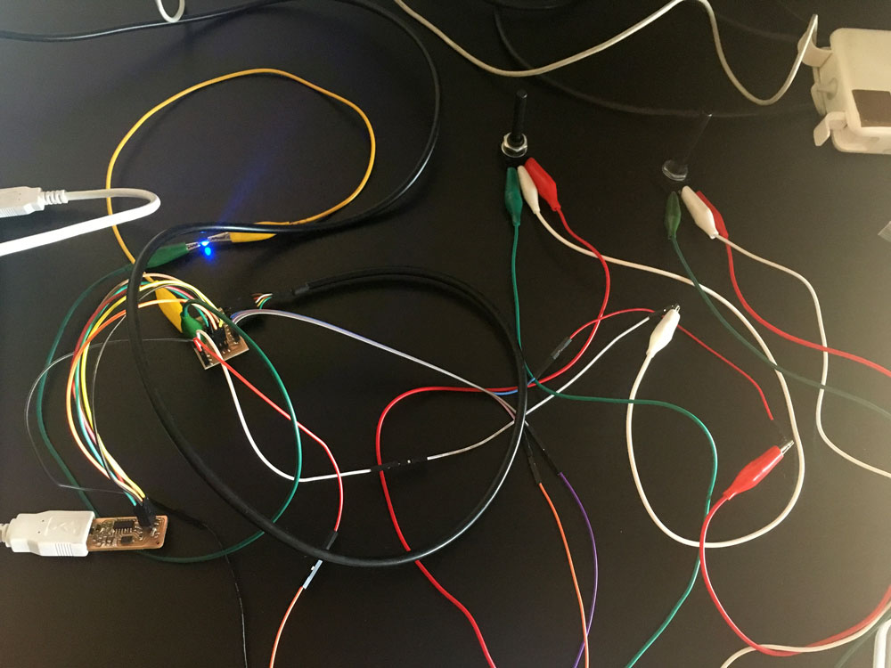
June 3, 2016First, I tested if the motor board was working properly, uploading a code to it to change the motor speed with the potentiometer input.
#include < Stepper.h >
int potPin = 7;
int potValue;
int motorSpeed;

const int stepsPerRevolution = 200;
Stepper myStepper(stepsPerRevolution, 0, 1, 3, 4);

void setup() {
}

void loop() {
  potValue = analogRead(potPin);
  motorSpeed = map(potValue, 0, 1024, 0, 100);

  if (motorSpeed > 0) {
    myStepper.setSpeed(motorSpeed);
    myStepper.step(stepsPerRevolution / 100);
 }
}
It works! Time to mill the remaining 4 ones:
The family grows! I have unsoldered the 5th one, if I can handle it, I can add it at the end of the project.
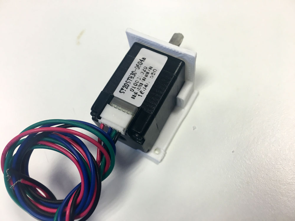
I also started to design a mount for the stepper motors in openScad.
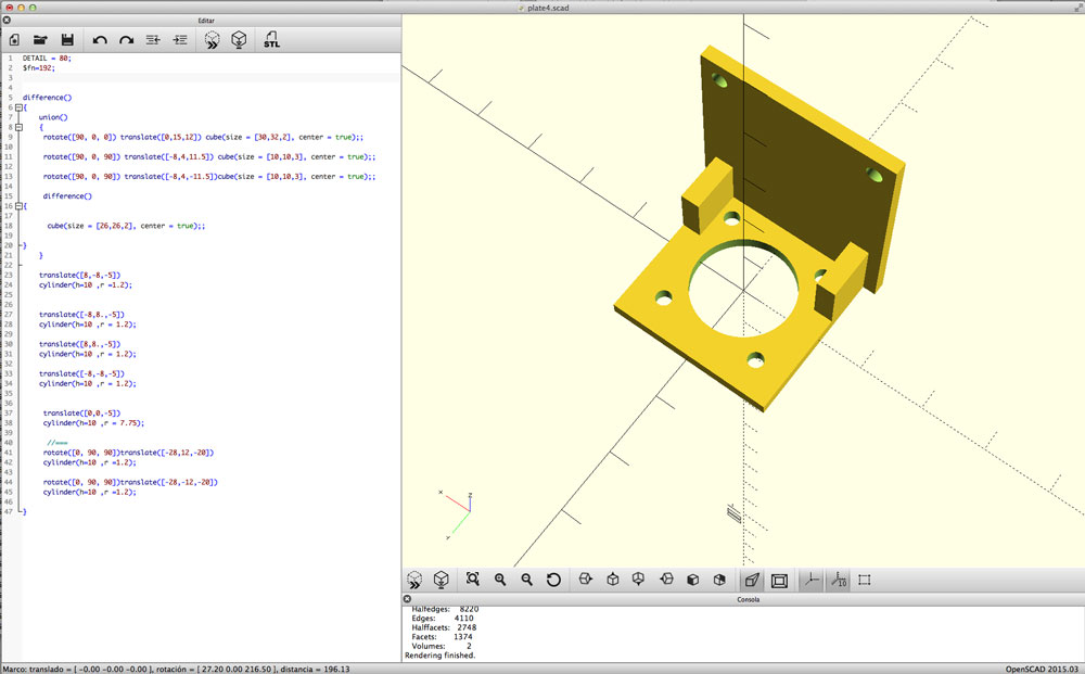
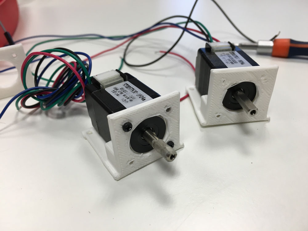
The tests are in very low resolution, but I´m happy with the results. The motor fits fine and is well fixed to the mount.
-
More coding
June 4, 2016Today, I started the code for the LED board. When I attached everything (unless the LED module, I don´t have it yet, so Im using an Arduino Lilypad one), I realized that the potentiometer for dimming the light was attached to the PB2 pin in the Attiny44, that corresponds with the Digital 8 in Arduino. Newbie fail (HOW???), and I was receiving 1023 value all the time.
Mill a new one or bridge it?. Make a bridge, of course, its Saturday.
#include < SoftwareSerial.h >

const int ledPin =  A7;
int ledState = LOW;

long interval = 1000;
int maxBrightness;

int potDimmer = A2;
int potInterval = A3;

int dimmerValue;
int intervalValue;

SoftwareSerial mySerial(0,1);

void setup() {

  pinMode(ledPin, OUTPUT);
  pinMode(potDimmer, INPUT);
  pinMode(potInterval, INPUT);
  mySerial.begin(9600);

}

void loop()
{
  dimmerValue = analogRead(potDimmer);
  intervalValue = analogRead(potInterval);
 // mySerial.println(analogRead(A2));
  maxBrightness = map(dimmerValue, 0, 1023, 0, 255);
  interval = map(intervalValue, 0, 1023, 0, 100);


  unsigned long currentMillis = millis();

  if(currentMillis - previousMillis > interval) {
    previousMillis = currentMillis;

    if (ledState == LOW)
      ledState = HIGH;
      analogWrite(ledPin, maxBrightness);
    else
      ledState = LOW;
      analogWrite(ledPin, 0);
  }
}
}
For the motor, I need to difference between spinning clockwise/counterclockwise, splitting the values incoming from the potentiometer and also adjusting the speed.
Left, incoming values from 0 to 511; and right, from 513 to 1023. The central 512 value equals to 0 speed.
                 #include < Stepper.h >
int potPin = 7;
int potValue;

const int stepsPerRevolution = 200;
Stepper myStepper(stepsPerRevolution, 0, 1, 3, 4);

int stepCount = 0;
int motorSpeedLeft, motorSpeedRight;

void setup() {
}

void loop() {
  potValue = analogRead(potPin);
  motorSpeedRight = map(potValue, 512, 1023, 0, 100);
  motorSpeedLeft = map(potValue, 0, 511, 100, 0);

    if (motorSpeedRight > 0 || mortorSpeedLeft > 0) {
      //clockwise
      if(potValue > 512){
           myStepper.setSpeed(motorSpeedRight);
           myStepper.step(stepsPerRevolution / 100);
      }
      //counterclockwise
     if(potValue < 511){
           myStepper.setSpeed(motorSpeedLeft);
           myStepper.step(-stepsPerRevolution / 100);
      }
    }
 }
-
3D modelling, 2D designing & LED module
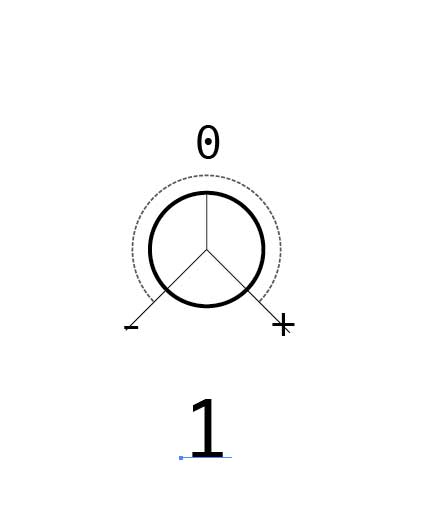
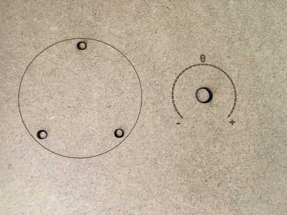
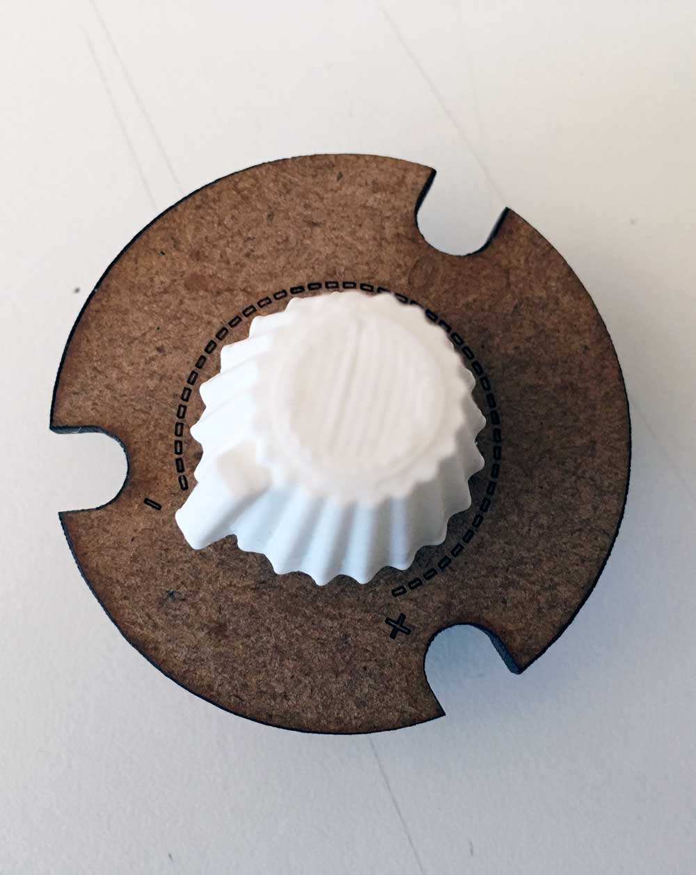
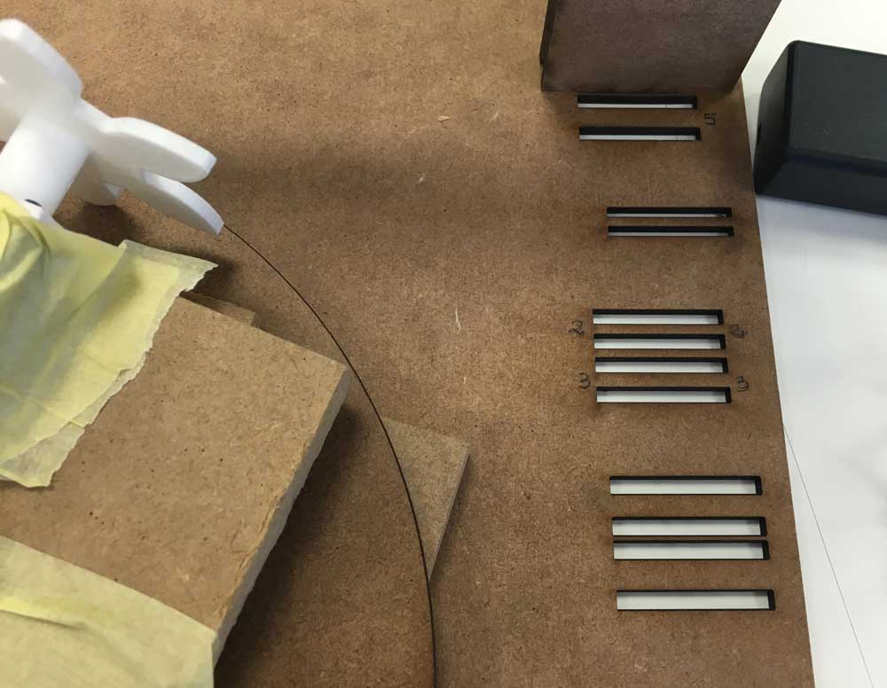
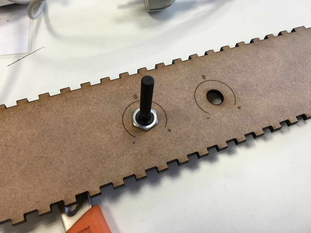
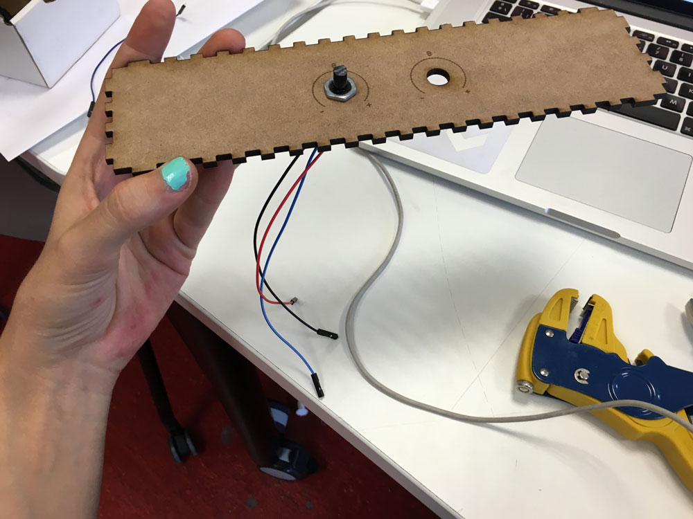
June 5, 2016Today, I started thinking about the control panel for the device. As the input are mainly (only) potentiometers, the angle rotation for this common potentiometer is of 270º, so I started figuring it out how will be the presentation. I should have marked this minimum and maximum range:
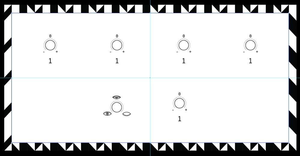
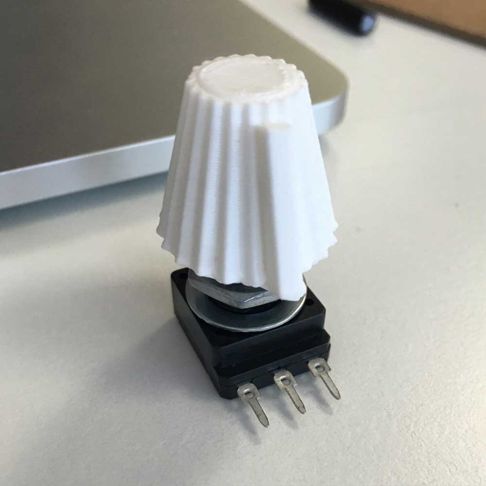
Also, as I started with at the molding & casting week designing a knob for the potentiometer, I adjusted it to my sizing in openScad, to generate a STL and 3D print it.
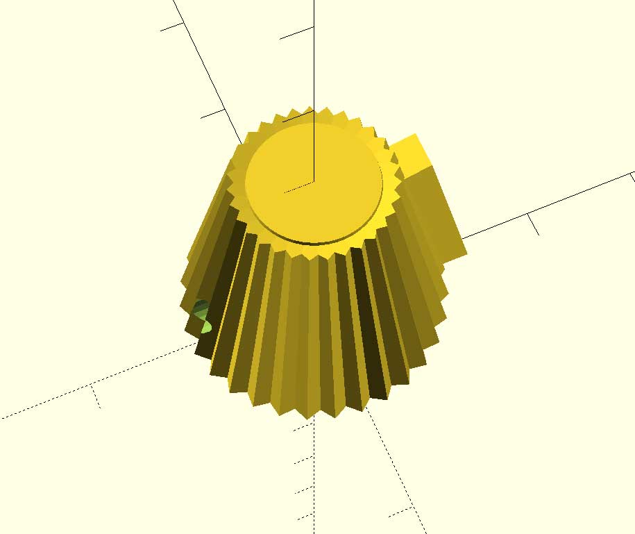
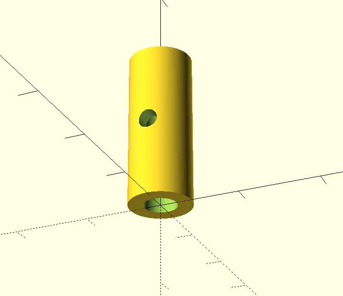
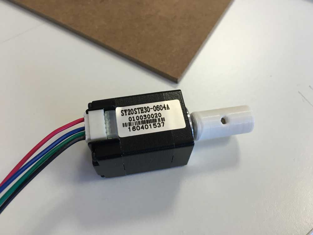
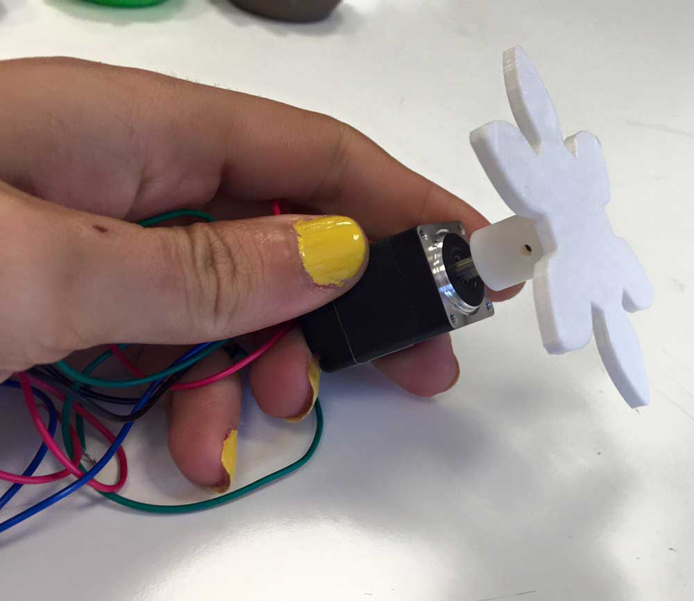
And a piece for attaching a gear to the motor´s shaft.
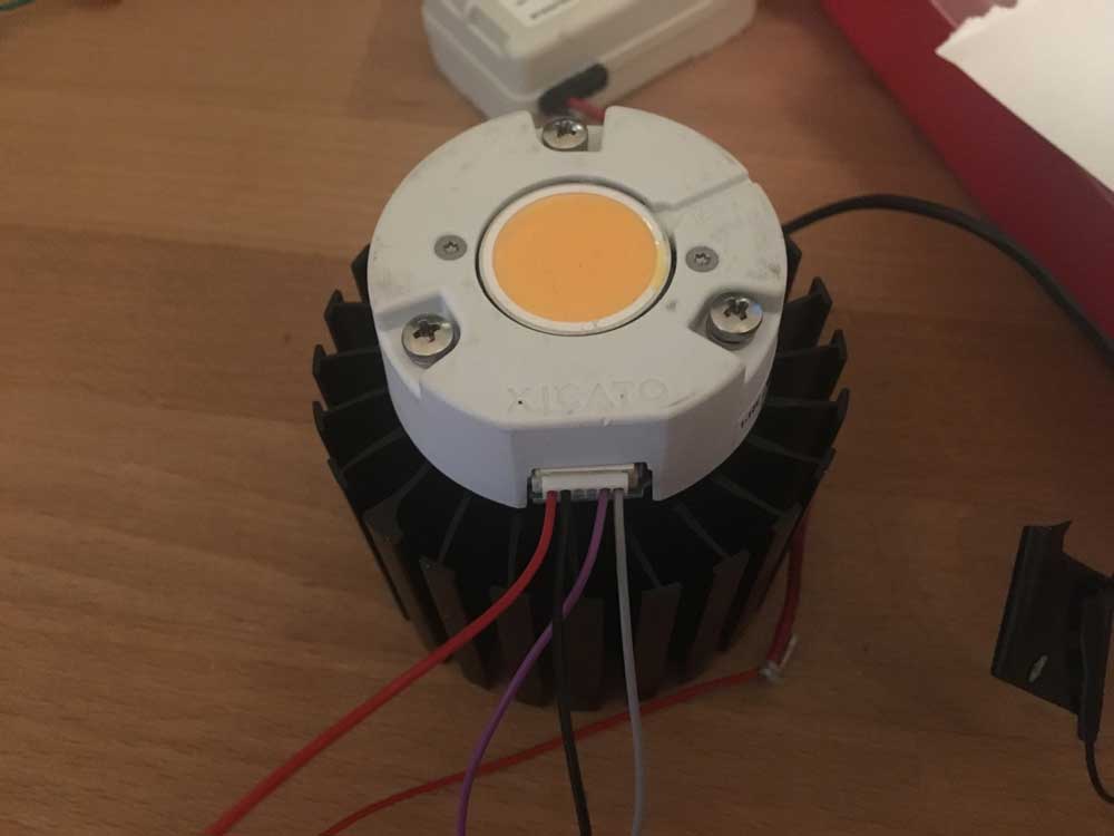
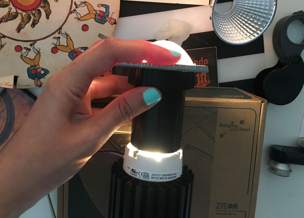
By the end of the day, I got the LED module I want to use for the final project. It´s a LED Module 0-10V from Xicato. The output I can get from the FTDI USB from the board only goes up to 5V, but I don´t really care, 5V its super bright:
-
Starting 3D Printing & Laser Cutting
June 6, 2016Today I started to print the models I designed yesterday.
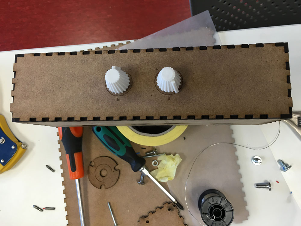
3D printing the knob for the potentiometer:
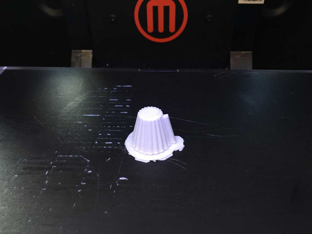
It´s too long :)
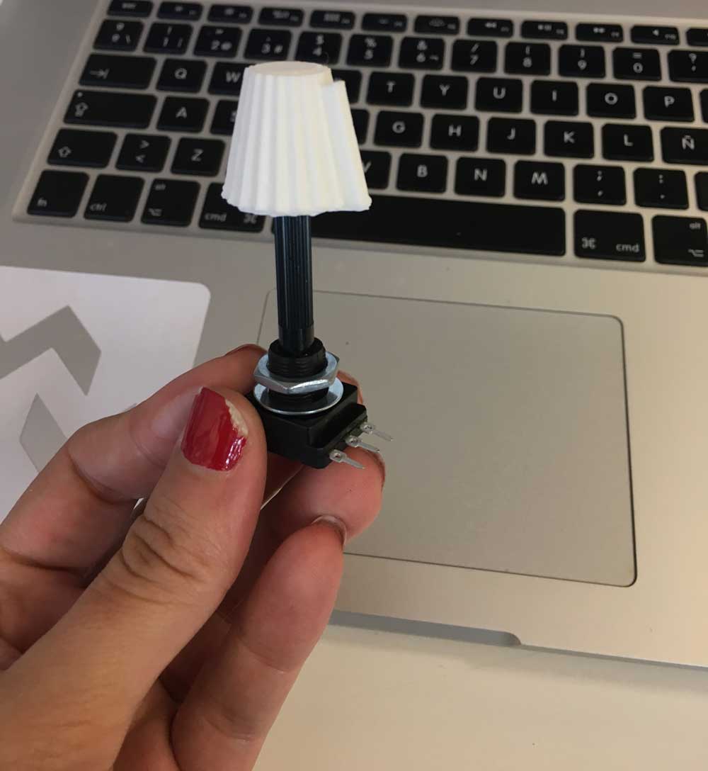
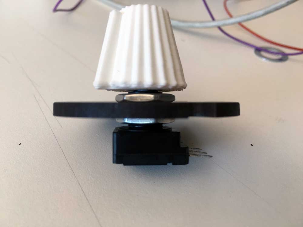
After cutting the shaft it fits perfectly:
I also started to measure the fitting for the gear attached to the motor´s shaft (with no gear yet, only testing):
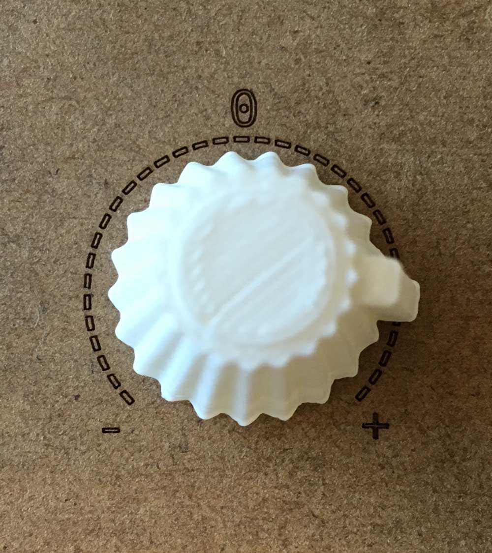
Laser cutting & engraving with 3MM plywood. Looking for the measures to fit the LED module screwholes and the potentiometer properly:
Cute control!
-
Gears
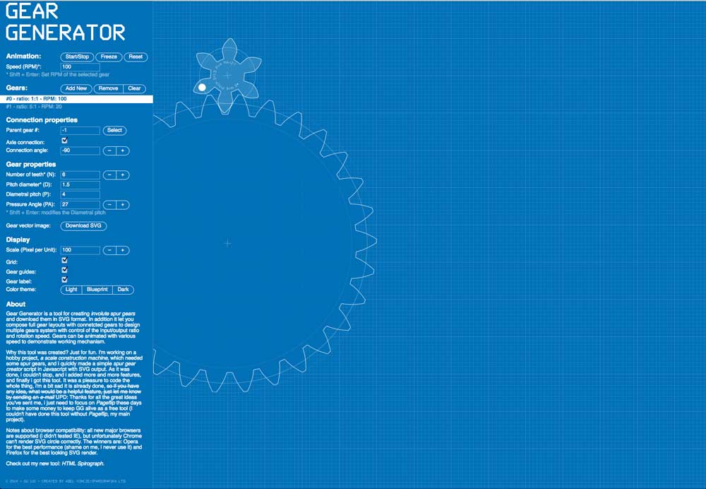
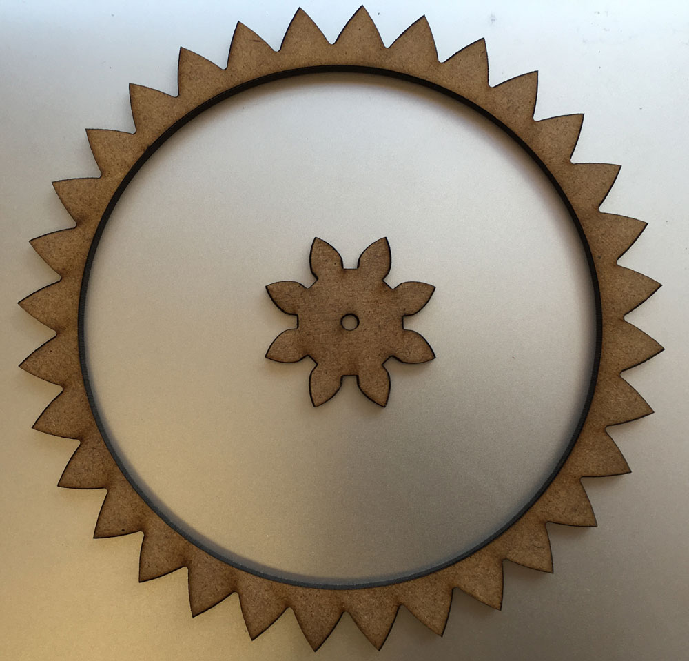
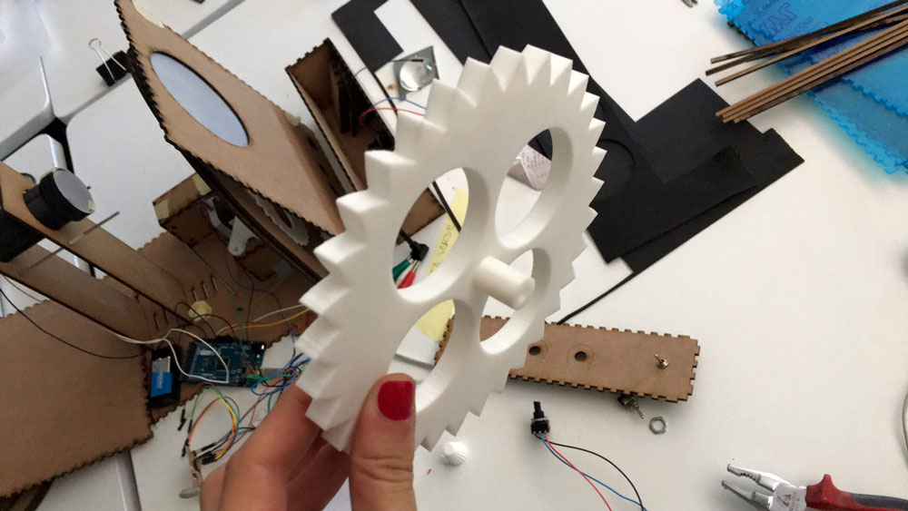
June 7, 2016Today I started the worst area for me: construction and gearing. I found a super cool online tool called geargenerator, that allows customize gears and even simulate the movement; and download svg files.
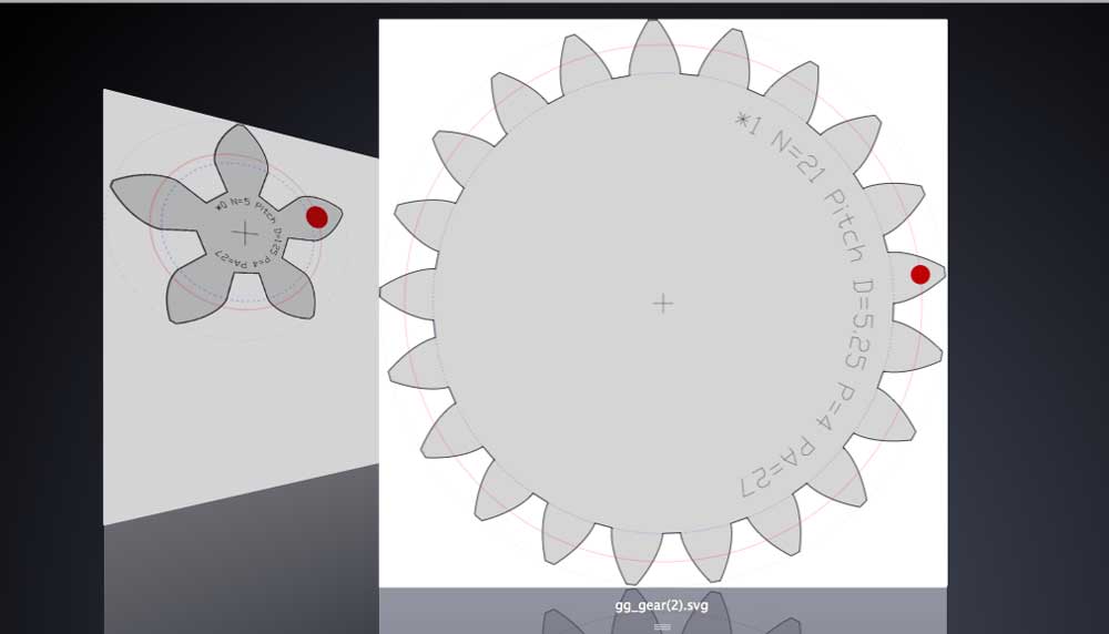
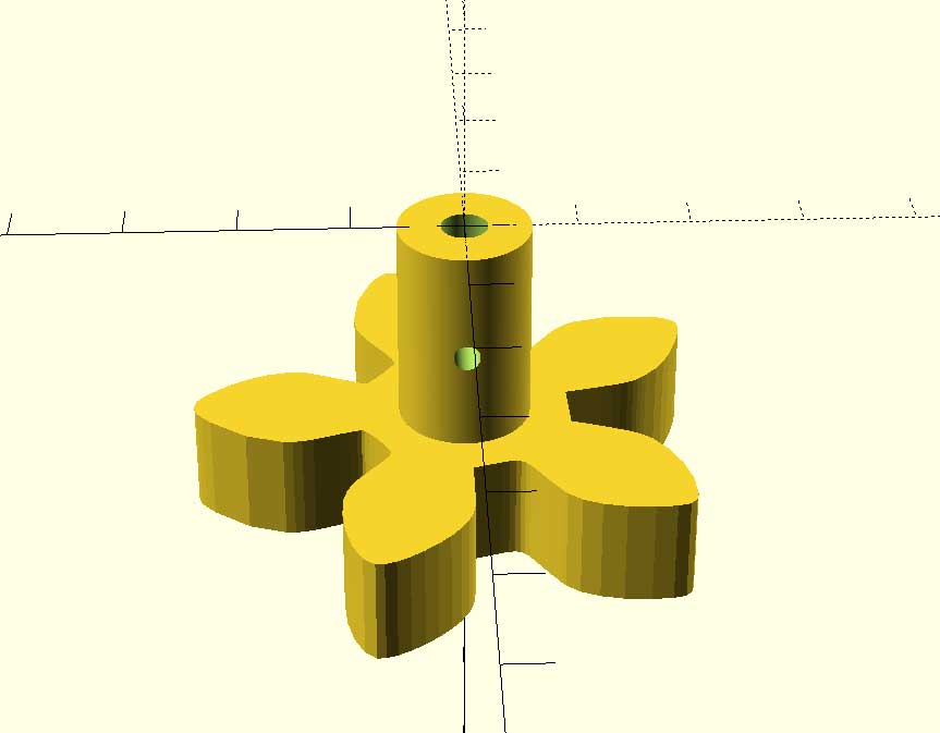
The small gear it´s going to be attached to the gear´s motor, so I needed to extrude it from 2D to 3D.

And then attach it to the shaft I designed two days ago that sucessfully fitted with the motor´s shaft. Again in openScad.
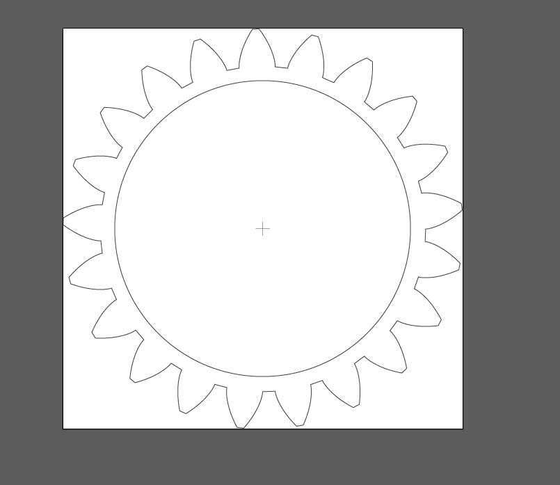
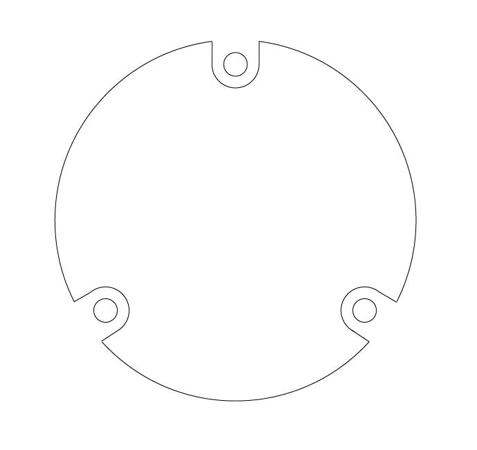
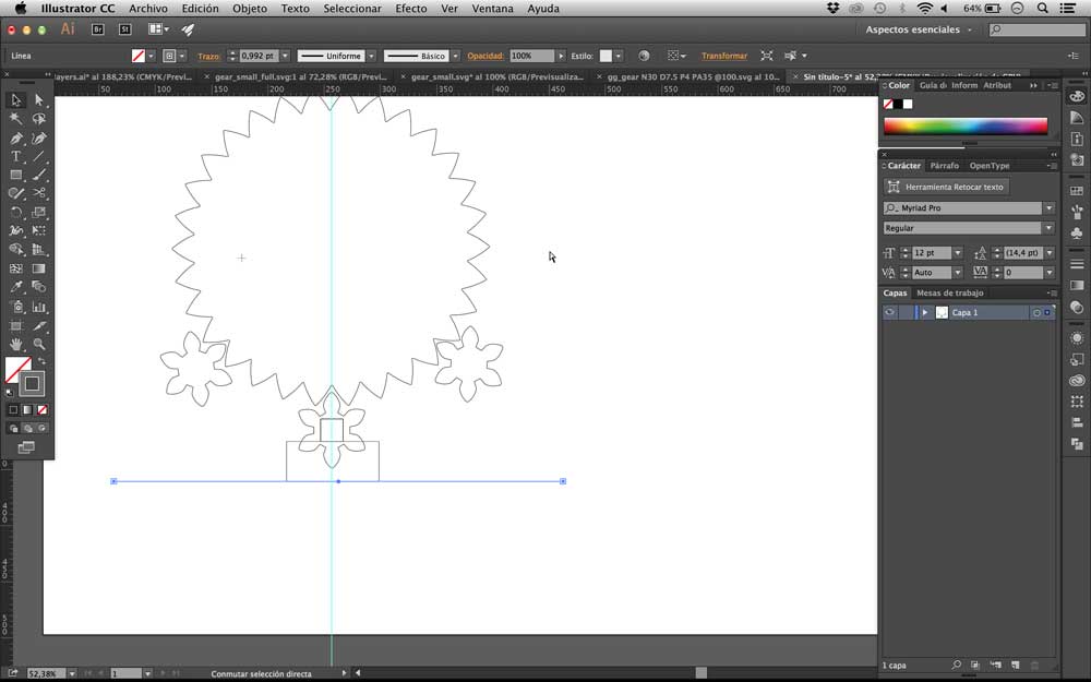
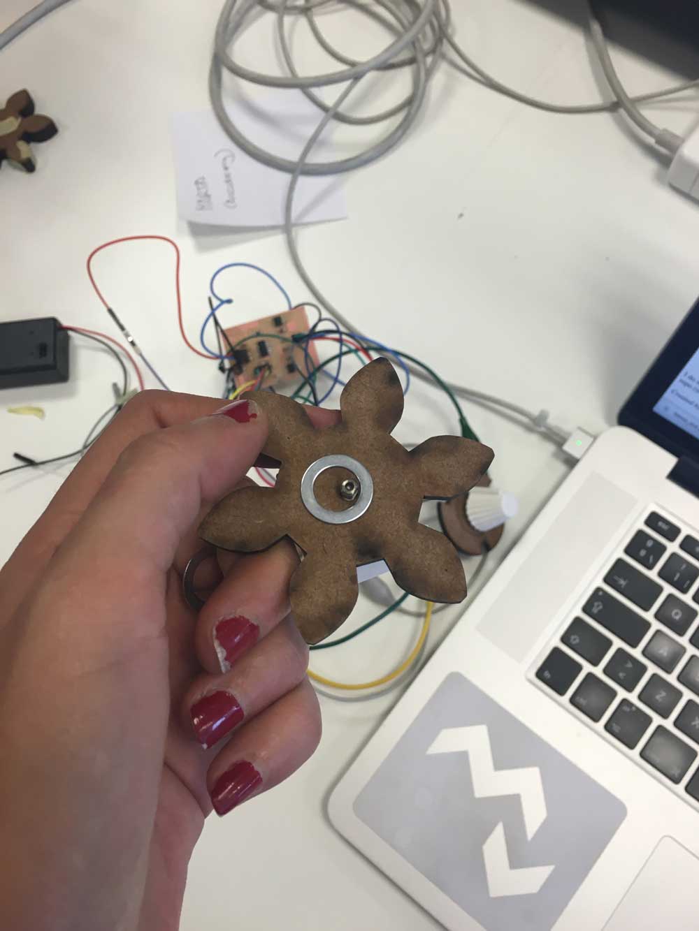
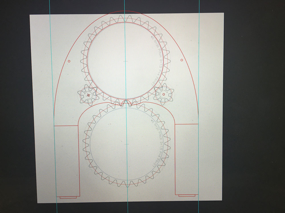
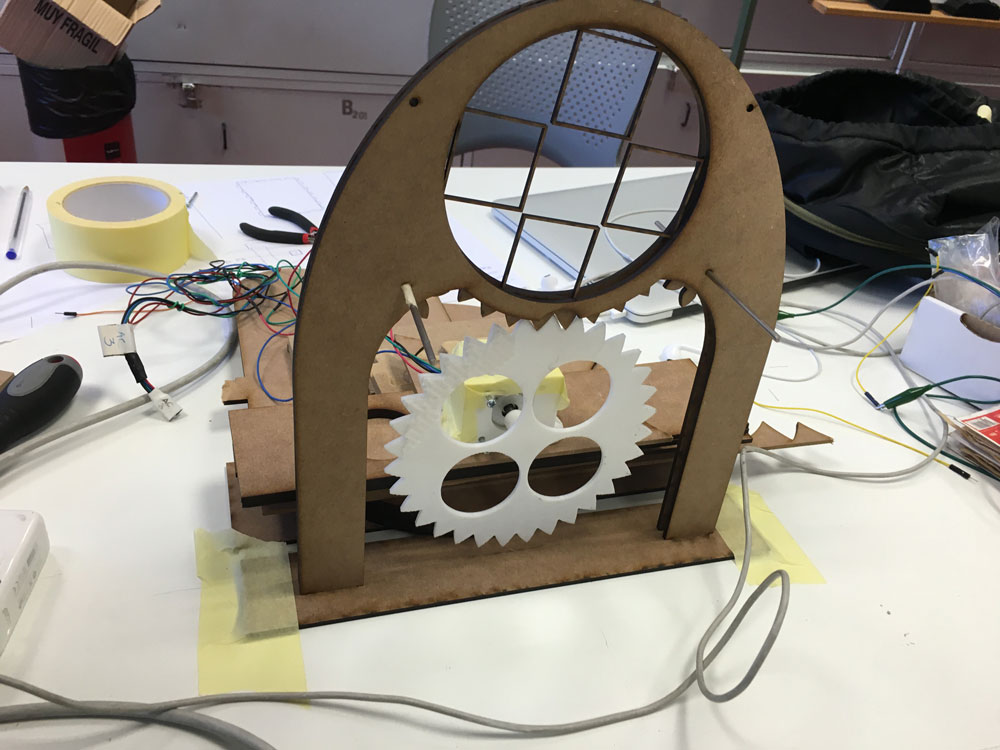
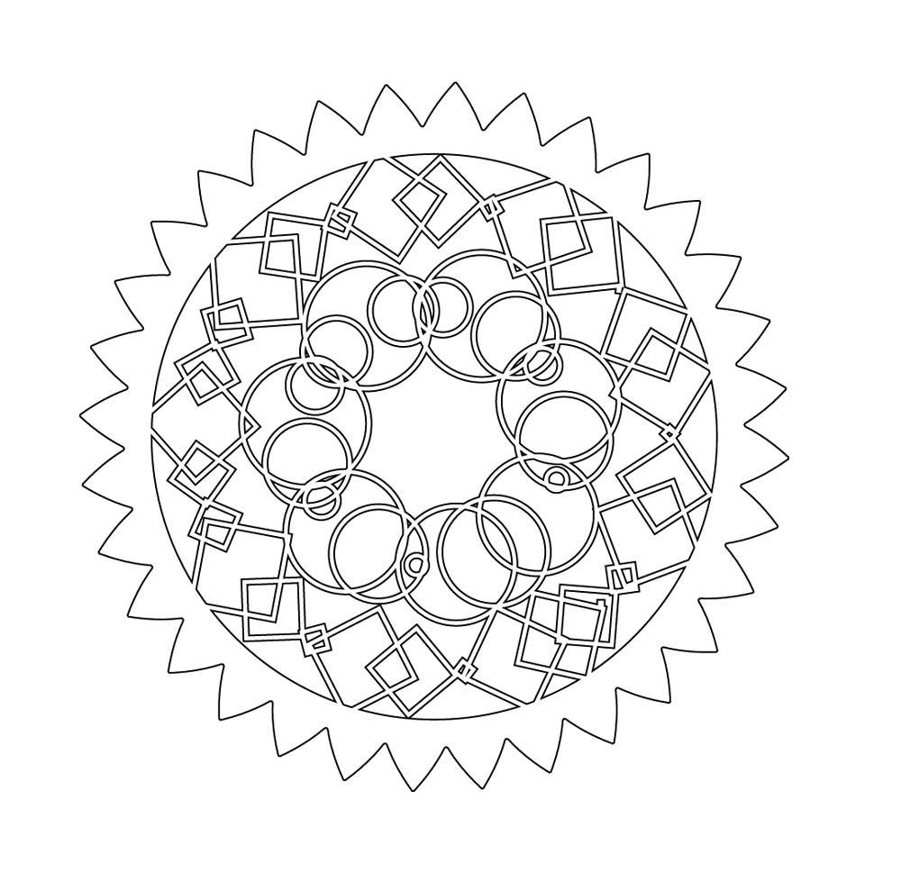
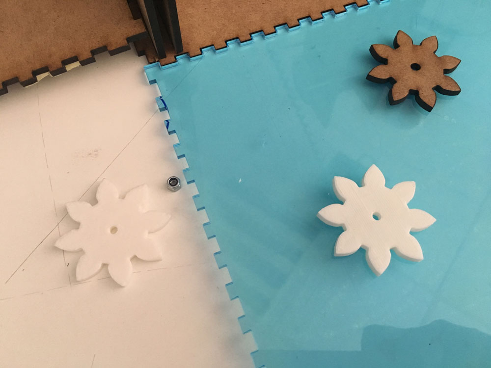
The big one it´s going to be laser cutted:
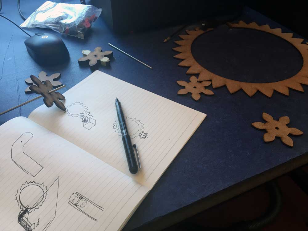
Now I can start planning the real thing, just sketching but approaching:
I also fixed the shape cut for holding the led module with the inner screws:
-
Laser cutting & gears
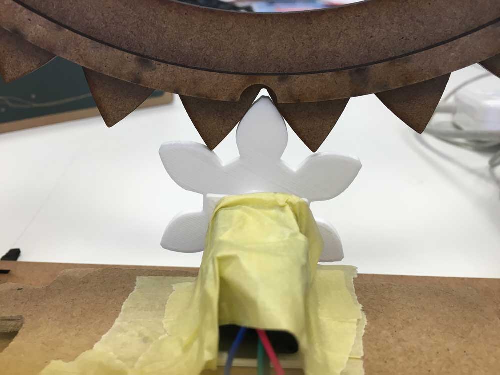
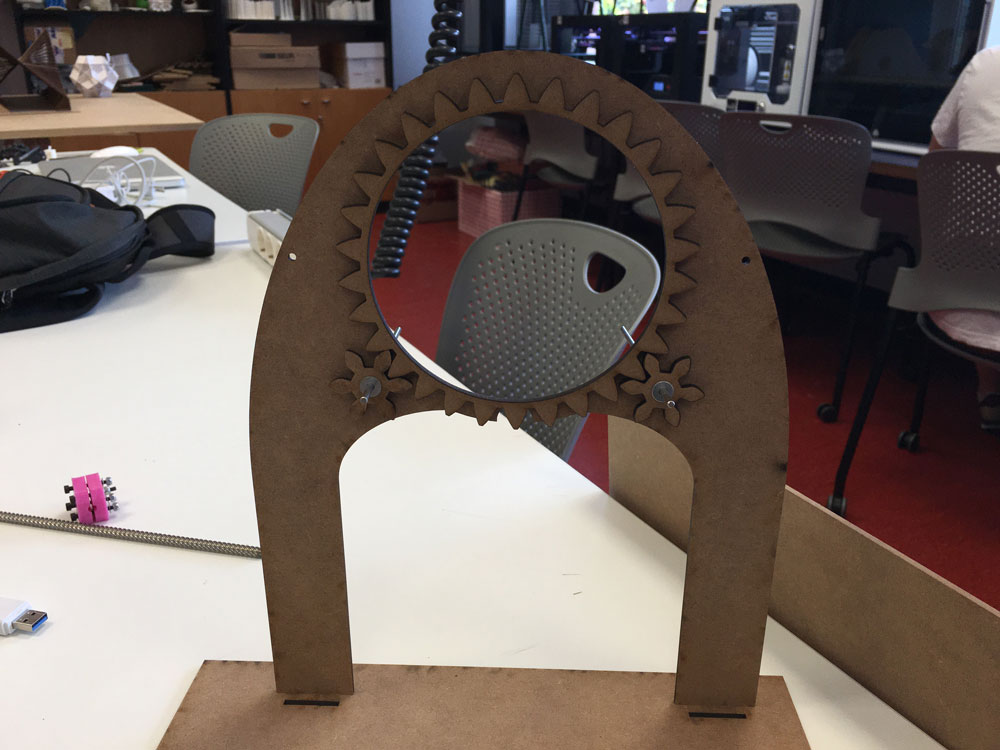
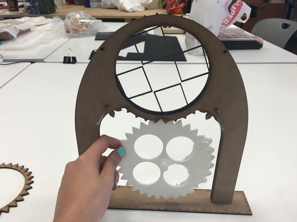
June 8, 2016Ok, time to make my ideas physical. First I tried the combination of the 3dmodel gear + the laser cutted one, with no luck, maybe I measured it wrong.
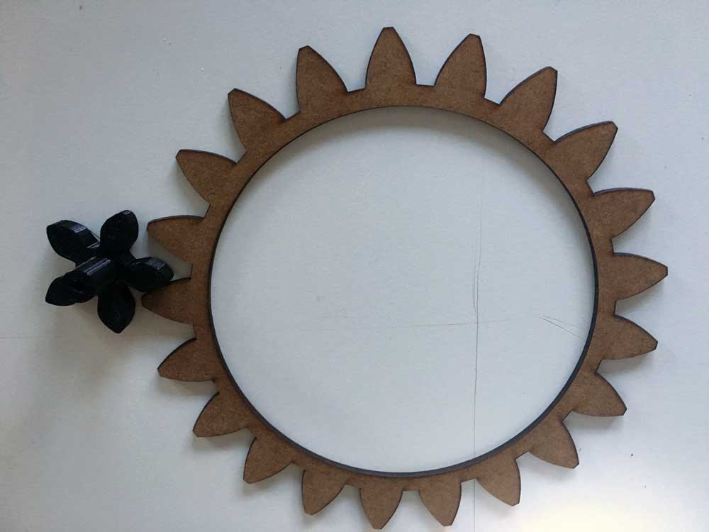
To save time, I laser cutted everything again to test fittings, with a new couple of gears, with more luck:

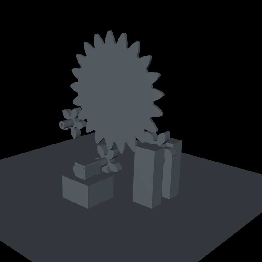
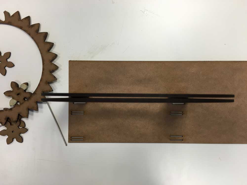
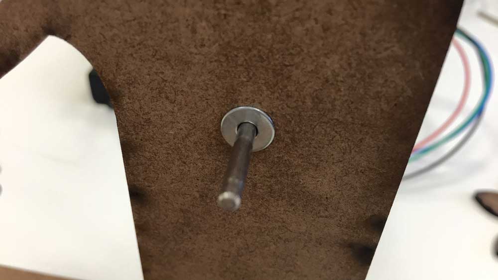
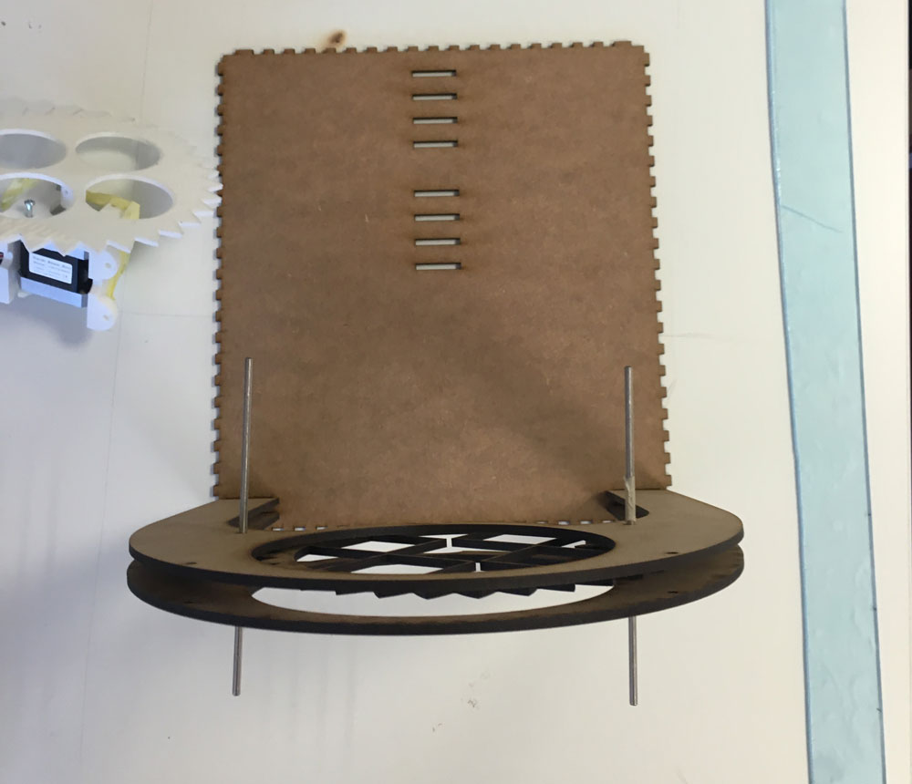
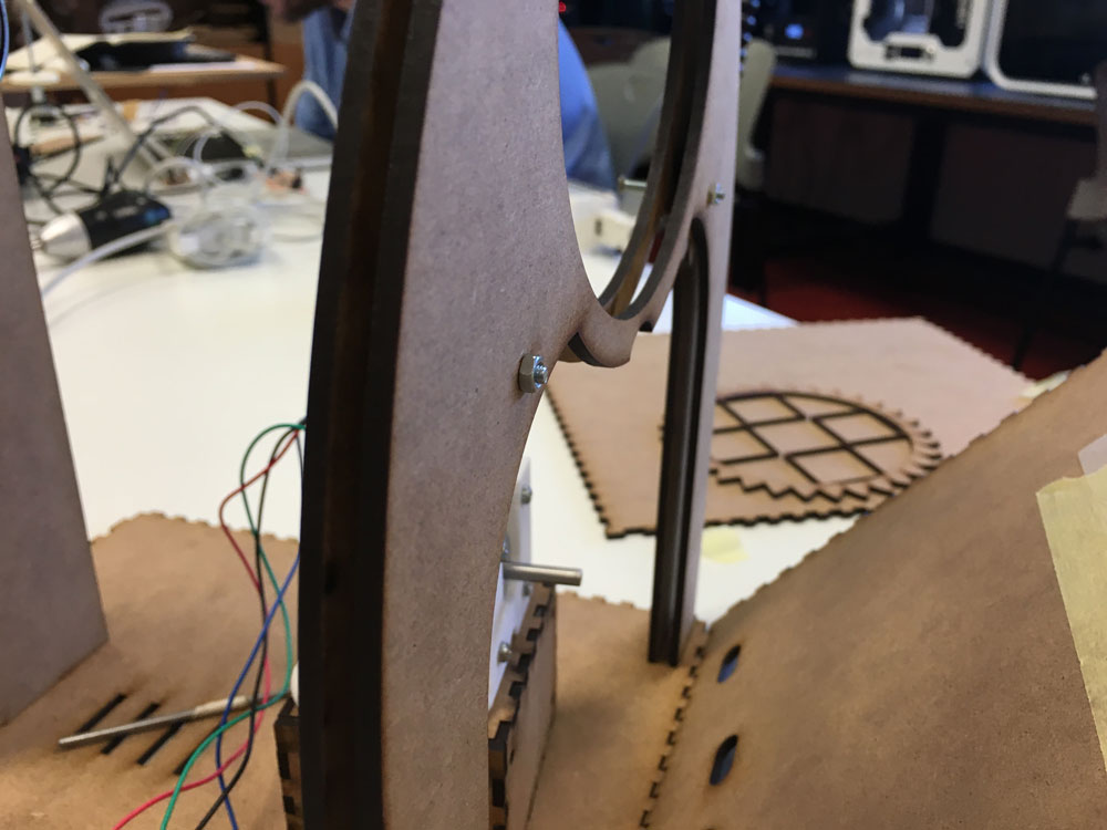
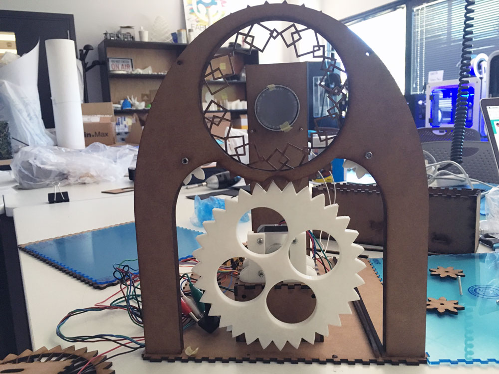
And started to think about the whole system, I need to put some support for the discs to avoid them to tilt.
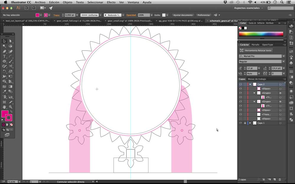
I thought that it would be better to have all the disc´s perimeter covered to play safe:
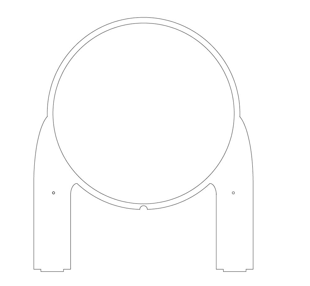
It fits!
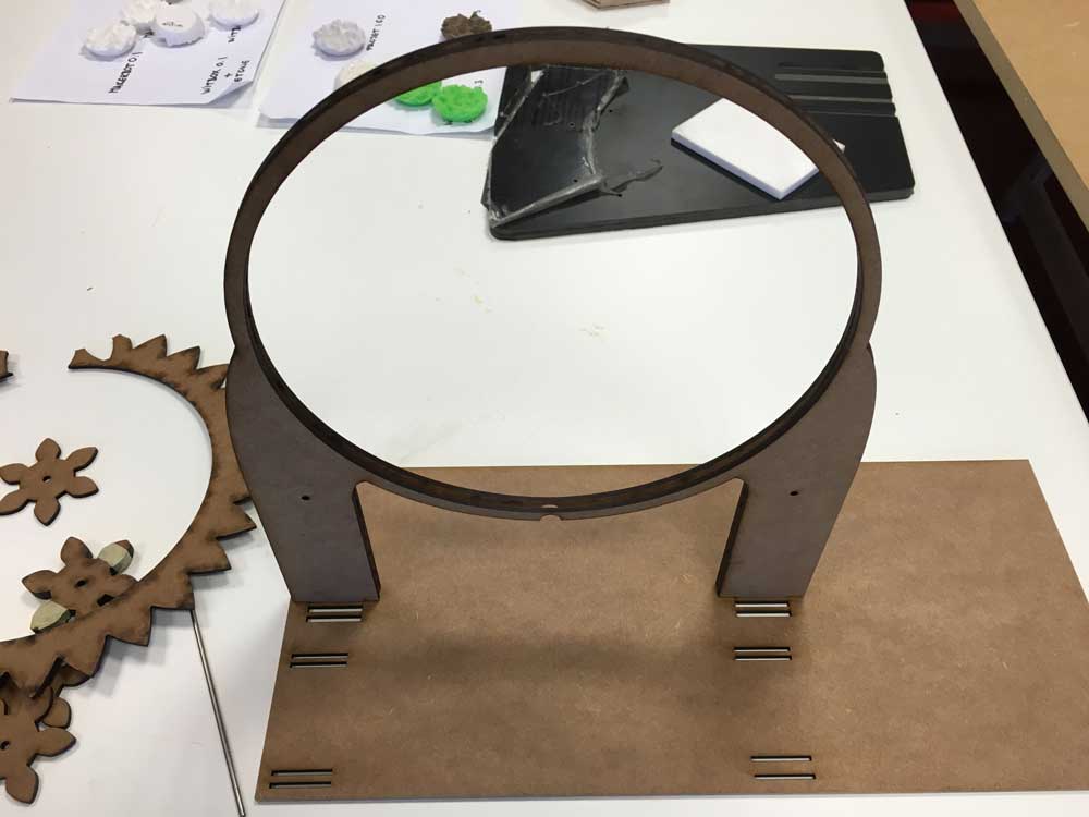
The idea seems to work:
And also I worked with the potentiometer attachment:
-
Prototyping
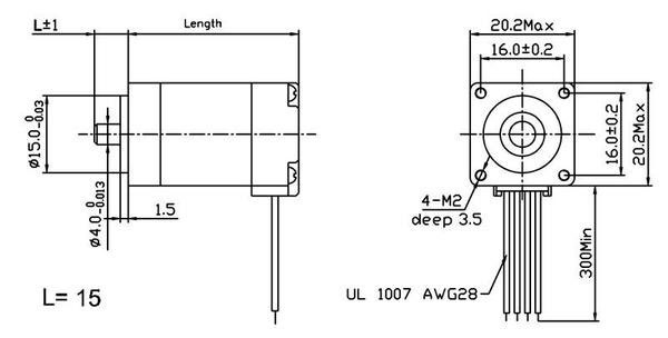
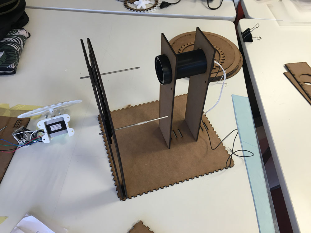
June 9, 2016Today I spent the whole day testing the nema8 stepper motor with my structure. I put some metal earrings to make easier the movement between the gears. They are big but the only ones I found around, I will buy the proper ones.
Feeding it with a 9V battery, the motor needs a little help at the beggining to start spinning and had random stops. With 12V it has more strenght but I can´t put them for too long because the external power supply I have has only regulable voltage, and it´s giving the motor too much amps. We don´t have a regulable power supply.
-
More prototyping & Coding
June 10, 2016Today I started working a little bit on my Processing app, and 3D printing the right gears for attaching to the motor´s gear. They fit better than the laser cutted ones, they are more stable, I think that yesterday it suddenly stopped because of that bad fitting of the gears.
Proper earrings:
Spacing between the two holding pieces:
I also tried to use a more "common" nema17 stepper, with 9V runs smoothly:
Why I´m not using the light?
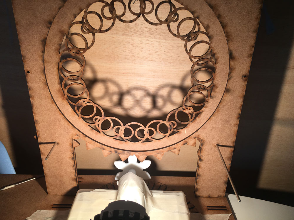
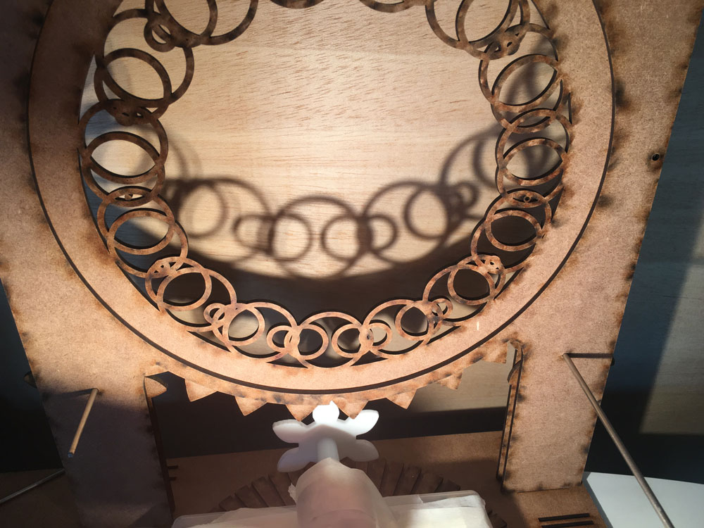
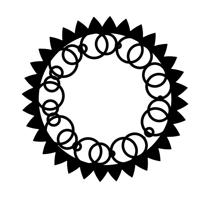
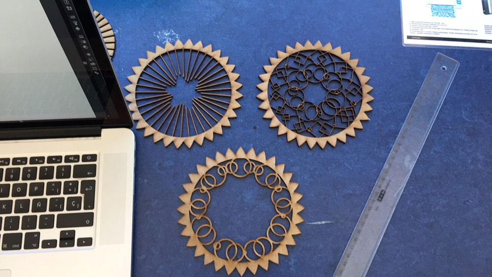
Let´s laser cut some discs with items, and a new stronger holding pair of slices:
Two similar layers:
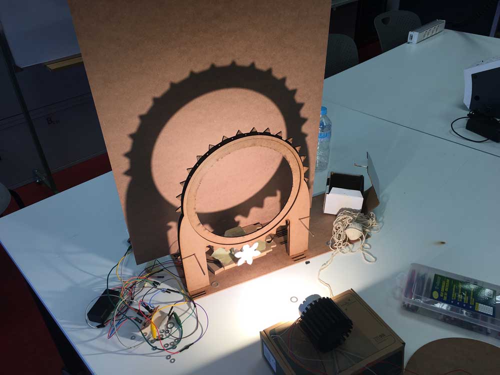
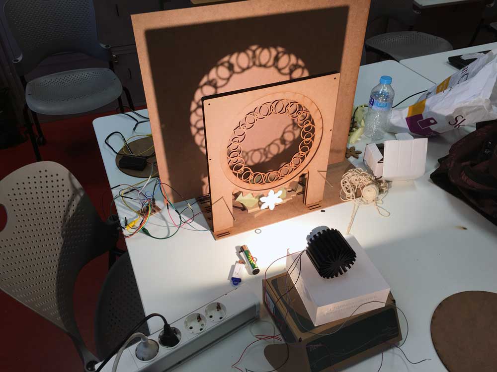
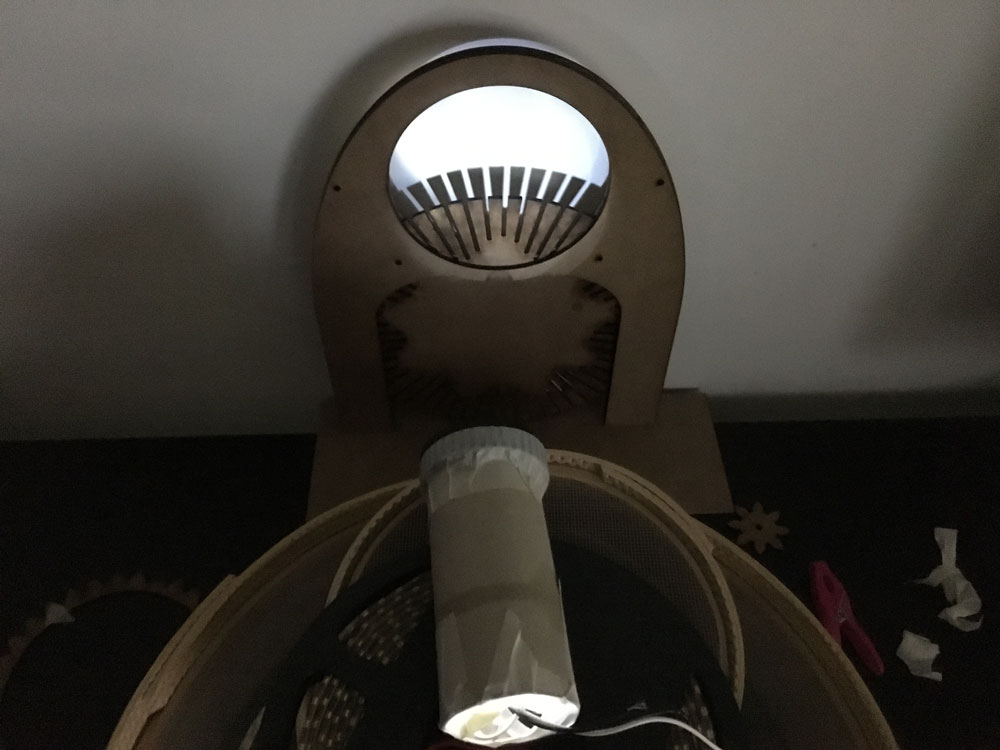
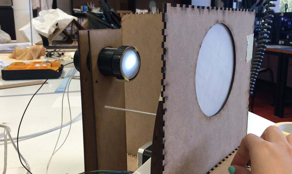
I need to focus the light because in this arrangement it gets too much dispersed, and I need to put the surface quite close to the discs to get a focused shadow. I also need to work with the spacing of the layers, they won´t be of the same size, they need to increase as they get far from the light source.
With these motors, even nema8 or nema17, i´m not getting the enough speed for create the optical illusion, I need the gears speeding faster. Maybe I try with a DC motor to see the difference.
-
More testing
June 11, 2016Today I tested a 12V 200rpm DC motor I found on a local store. It spins faster than the two steppers (as expected), I was lucky, the shaft was super similar to the nema17 one so I could fit the gear on it.
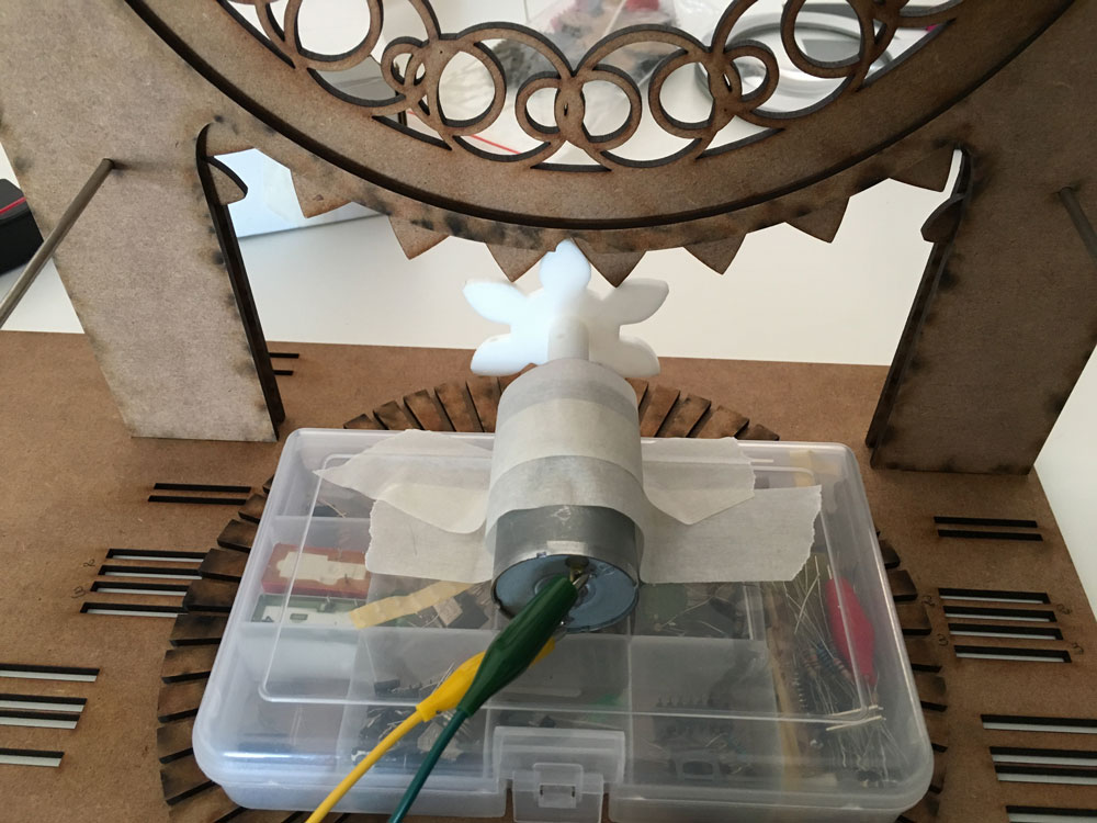
I had to stick it with tape as I could, because of its round shape is difficult to hold it, but it works fine, despite of the motor´s movement:
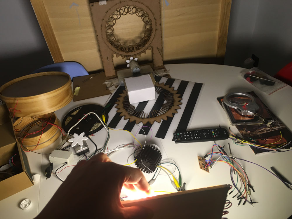
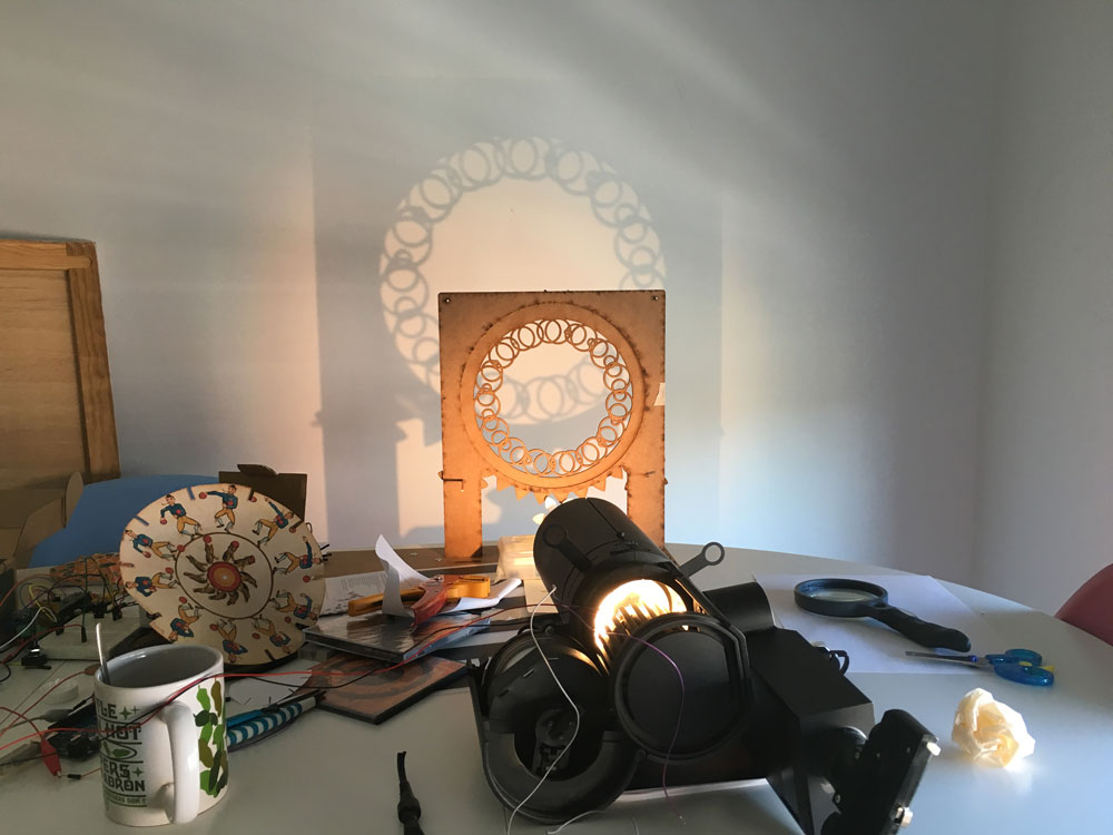
Time for test with the light.
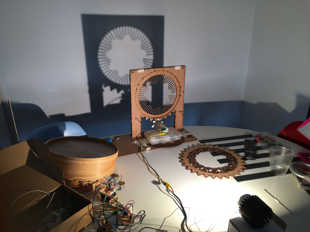
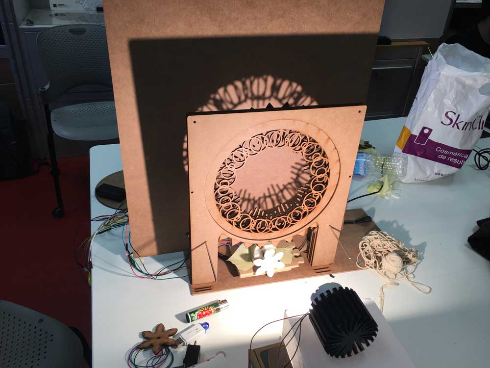
I realized that for getting a focused shadow, I really need to put the luminaire super far from the structure (more than 1 meter).
And worst, the Xicato LED Module is not responding as I expect to the blinking code. It takes too much "effort" and at low frequencies (400 ms or less) it didn´t even light up and the light didn´t reach the structure. It´s not a code problem, I tested the same with a white LED strip and works perfectly.
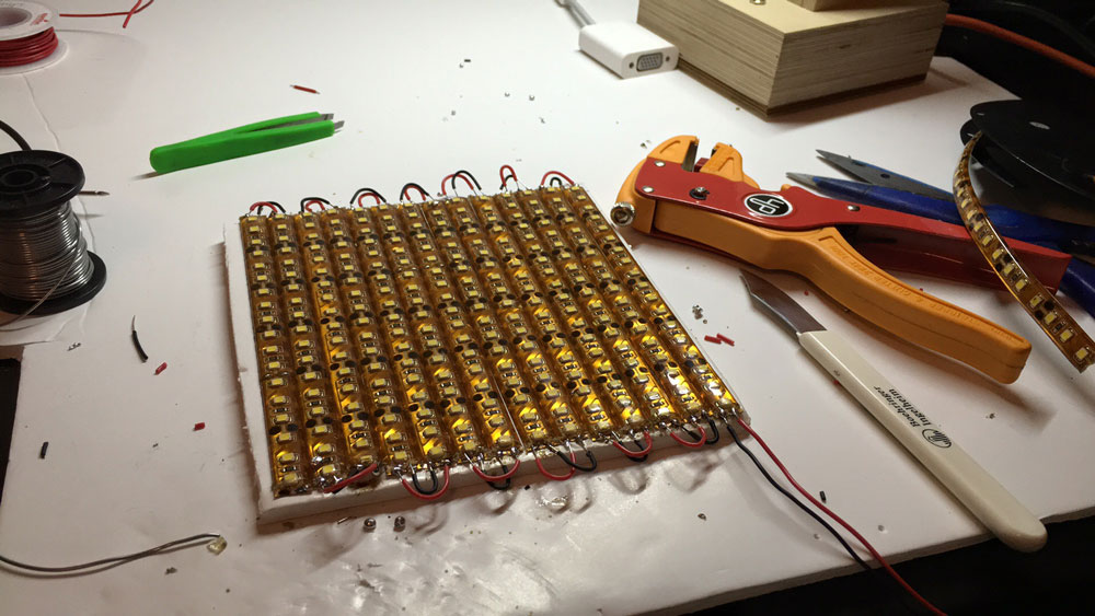
It was around midnight and I thought, If i build a led panel with led strips? and try it?
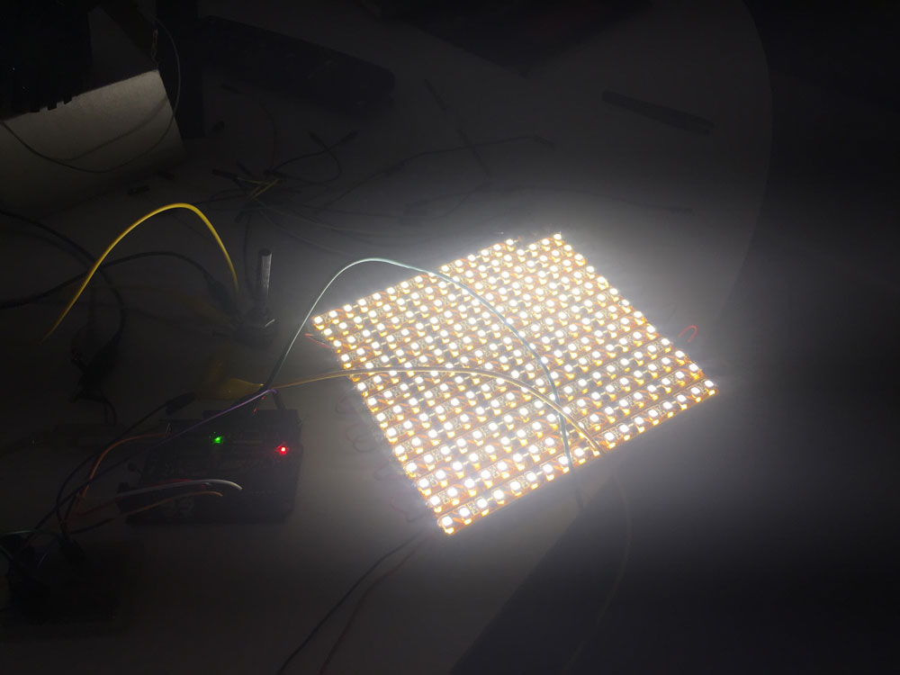
Bad idea. Time to sleep.
-
A little bit of reading
June 12, 2016Sunday, time to think about what I´ve done and what I have to fix. I took time take a look with some books. Making things move has an interesting chapter talking about gears and movement.
If I really want the fastest speed the motor can give, the two gears should be of the same size. If the little gear is half of the size of the big gone, the big will spin at half of the speed.
In addition, talking with my brother (is optometrist), he reccomended me to make the spinning items smaller, to avoid to put the light so far away.
By the other side, I found this interesting book about lantern projections. It talks a lot about how light beahaves, and the importance of use lenses to focus the light, and focal distances. IT also talks about a lot of different devices, chromatope, eidotrope....
I also found this other book.
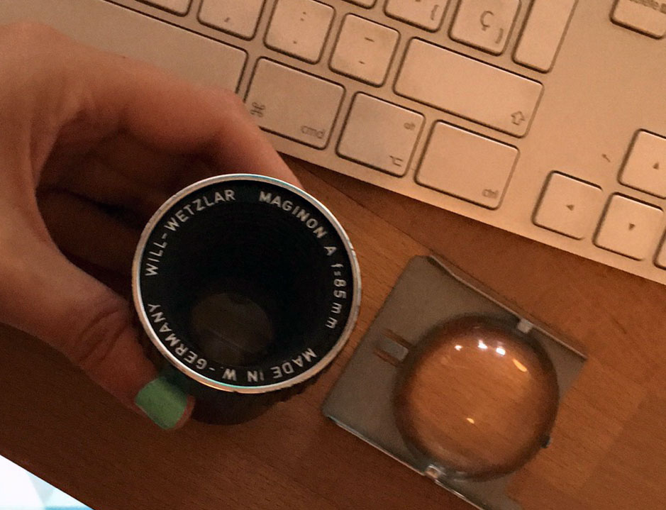
My brother recommended me to put a divergent lens between the light source and the structure. I dont have a reflex camera or something similar to try, only my lenses set for my iPhone.
With no lens:
With the tiny wide-angle lens:
It makes a little difference but it notices.
******* Considerations and to-dos ********
I should have started the process with the mechanic and lighting area, it´s taking a lot of time. If definetively I will use DC motors, I should re-fabricate the boards.
The same thing with light source, I need to look for a different light source that allows me to make the flikering to try to reproduce the animation feeling (I hope I can do it), if I use the Xicato LED module, it will be light up all the time (plan B).
Decrease the size of the items mantaining the same structure.
Play with some lenses (if I have time to get them, I hope I can, If not, It will be a huge cube.)
**** Late night ****
Why not to try to create flickering with the projector?

-
Stop & think
June 13, 2016After all that readings, why I didn´t tried at the beggining to build a "classical" zoetrope/phenakistoscope/fantoscope to study the light frequency and the spinning speed?
I totally forgot about a project that was already done, by a super cool studio from Catalonia, formed by teachers I had when I studied digital arts: playmodes studio.
I had everything I need, 2 potentiometers, a motor, a led strip and a board to drive it.
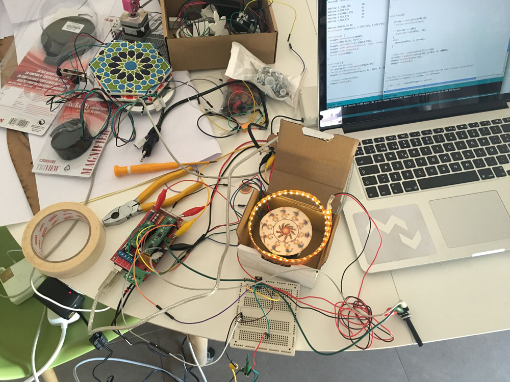
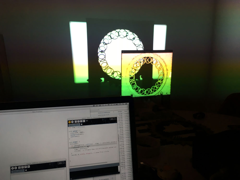
As I can see, with this speed and motor I can handle the effect:
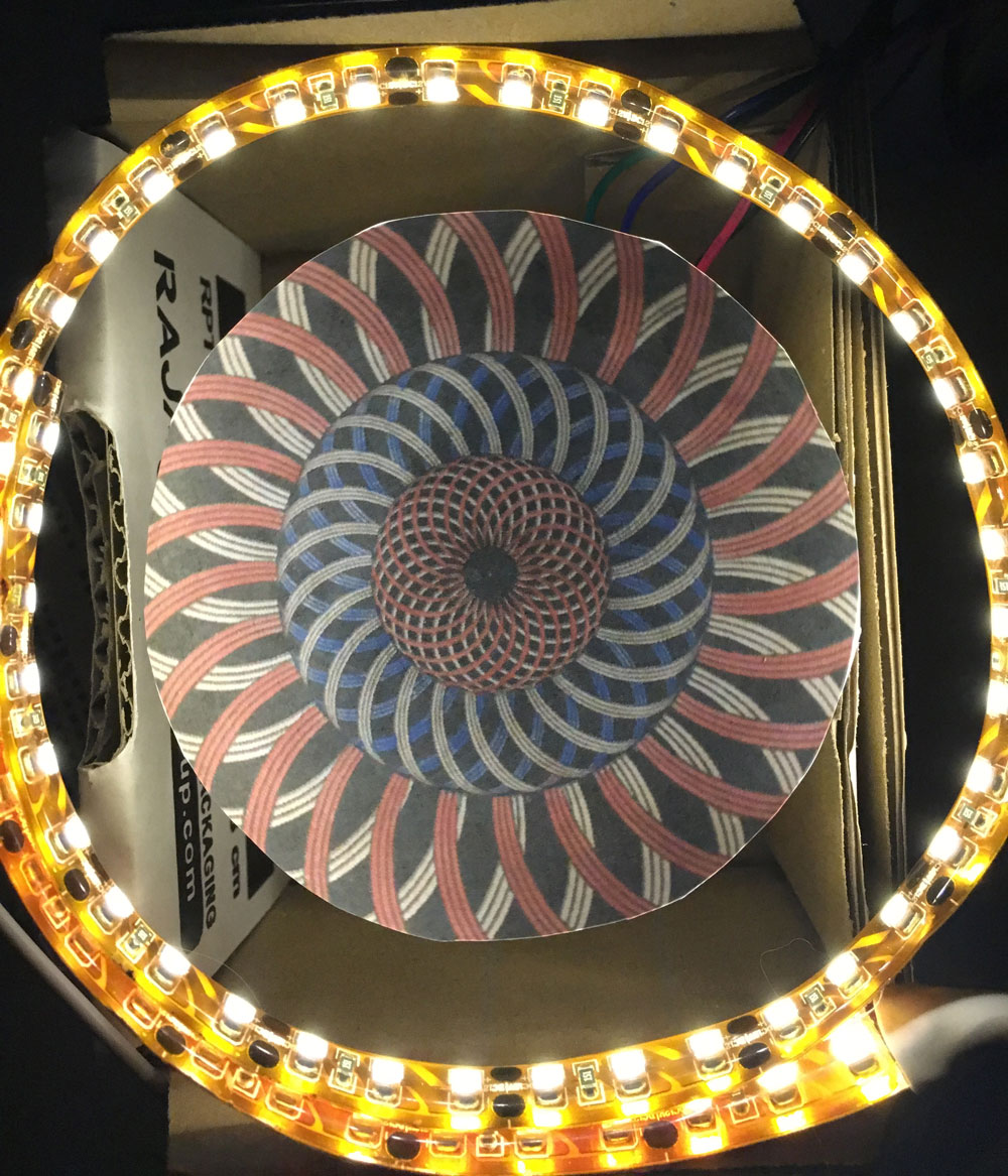
Sorry about the vertical videos and the sweeping...but with my eyes I really could see this animating:
Sucess! I only need to focus the light, and figure out what light allows me that flikering amount, of course...
-
Light
June 14, 2016First, I went to visit a Lighting design company who I work with sometimes, they borrowed me this luminaire with focus, just to check, but it´s really huge!!!
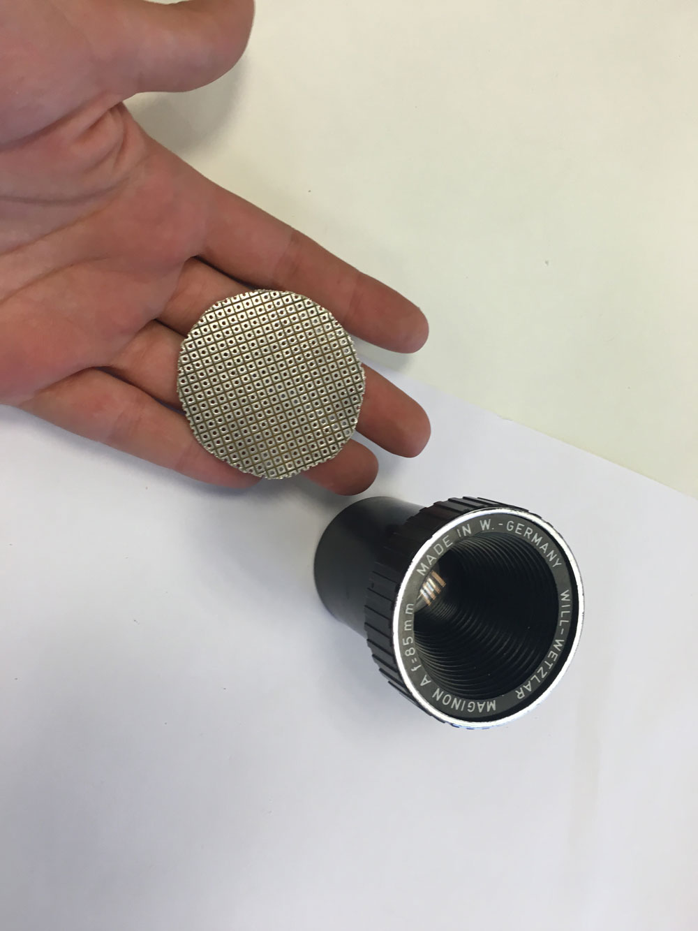
No way. I need something portable, and affordable too. I digged on the net and lucky me, found a girl who was selling (4 €), the lens of a slide projector, and he lives 10 mins walking of my place.
I made some tests with the Xicato module with satisfying results
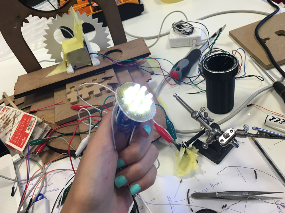
But I can´t use the Xicato, It don´t allows the flickering I need. I found some 5mm high brightness white LEDS (15 degrees of aperture, quite directional).
Only 1 LED!!
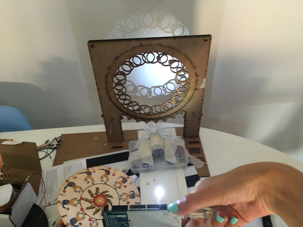
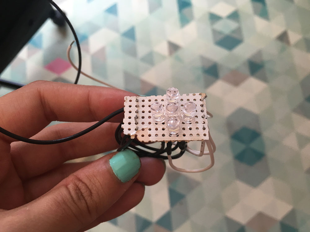
Let´s try with more than one (5; I´m prototyping with an Arduino Mega, each digital pin outputs maximum 20 mA), connected to the same pin and with the flickering code:
I soldered them to a perfored pcb piece:
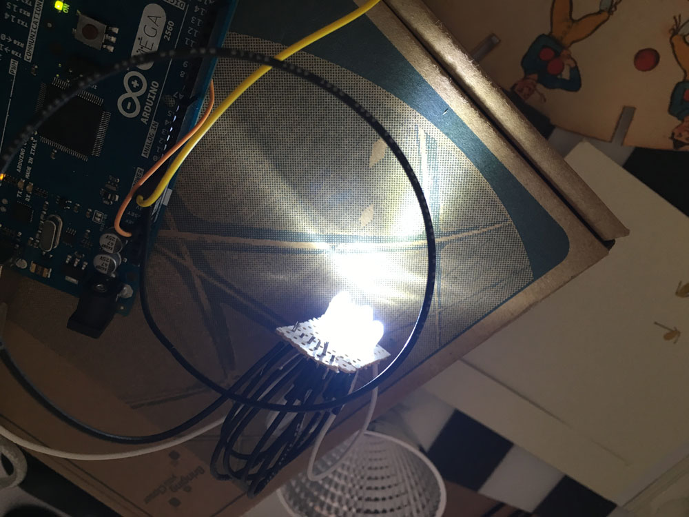
Just, for testing (and fun), I tested a LED lightbulb, and controlled the flickering with a relay:
But is not that fast as the led diodes. I chose my self-made luminaire.
-
Re-design & light
June 15, 2016Ok, I need to build my system smaller, and the motor and rotating gear should be of the same size to take full advantage of the motor´s speed. The system I already designed was working nice, so I changed measures and distances.
These pair of gears didnt run smoothly...
The good ones:
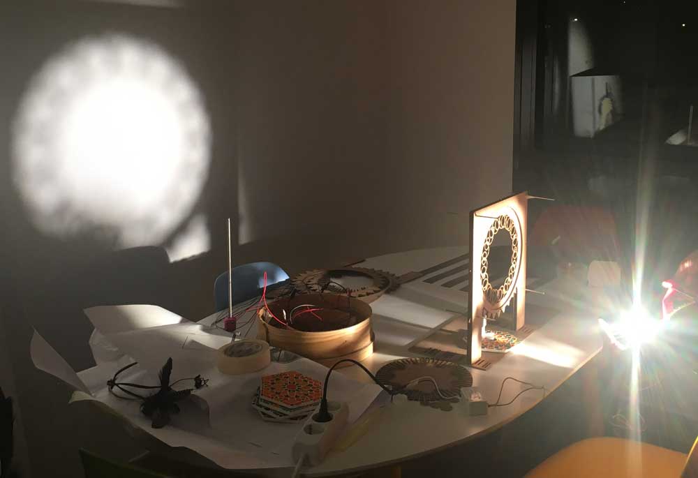
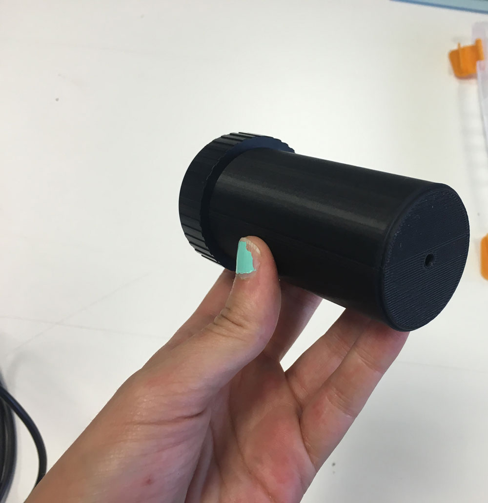
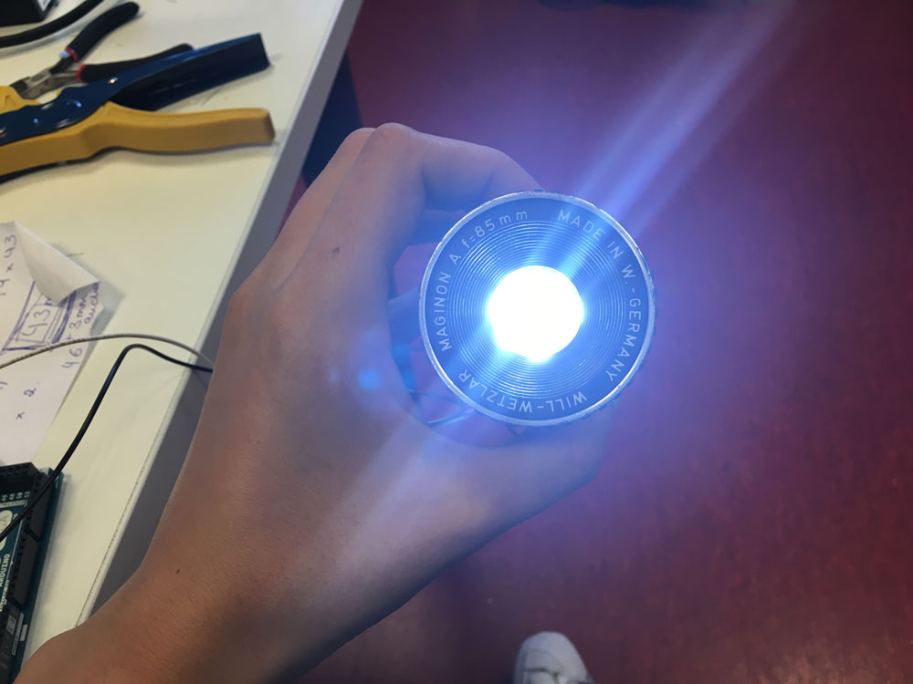
I liked the 5-led board, so I figured out how to join them to the recycled lens and not lose light. The lens fitted perfect on a carboard tube from kitchen sweaping paper...
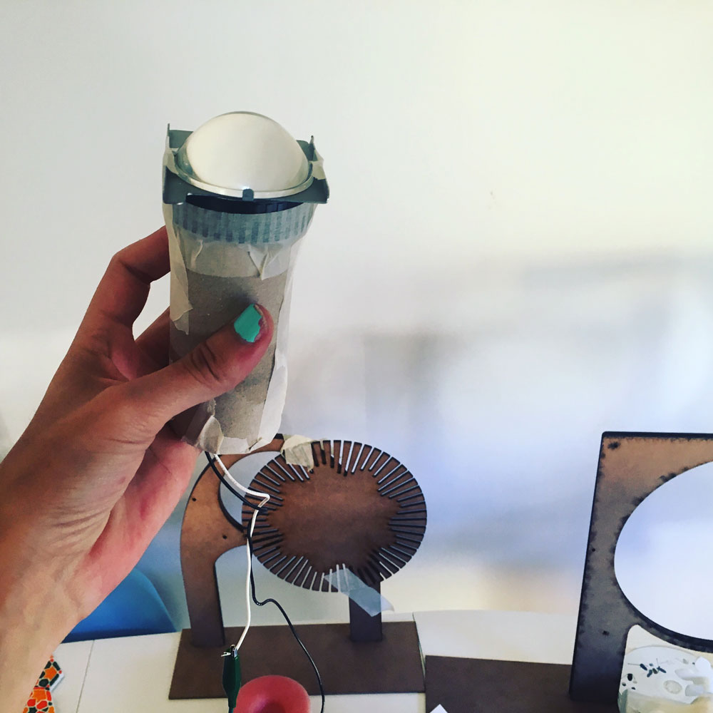
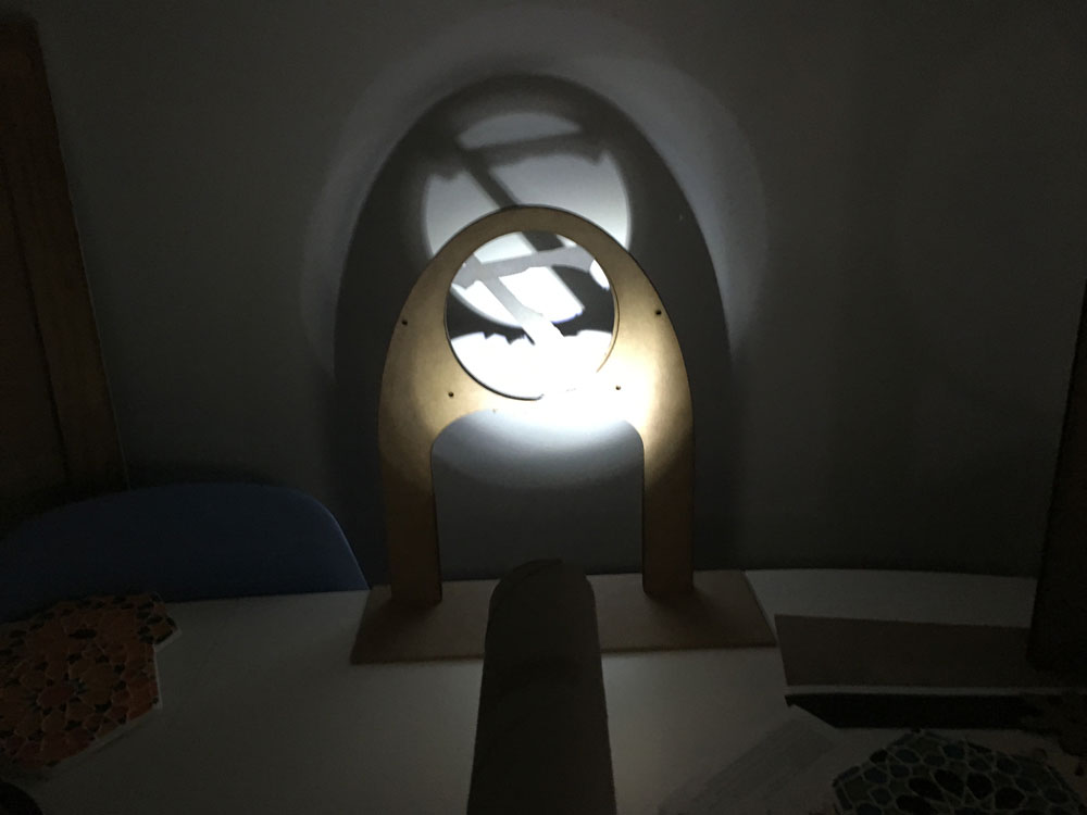
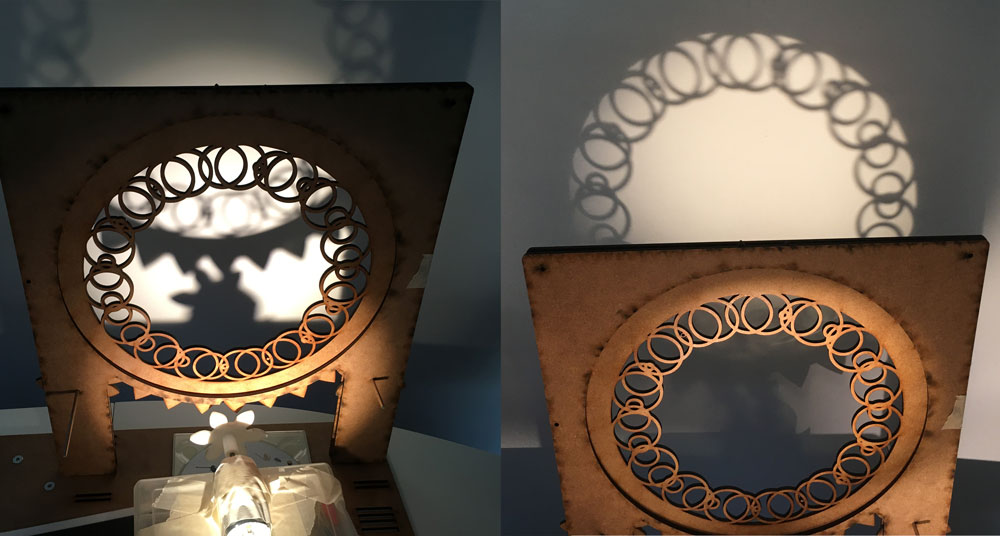
Just checking the difference between using the external lens or not, I got a more defyned shadow with the light source closer.
Mission acomplished!!!
-
Laser cutting, luminaire building & motor mount
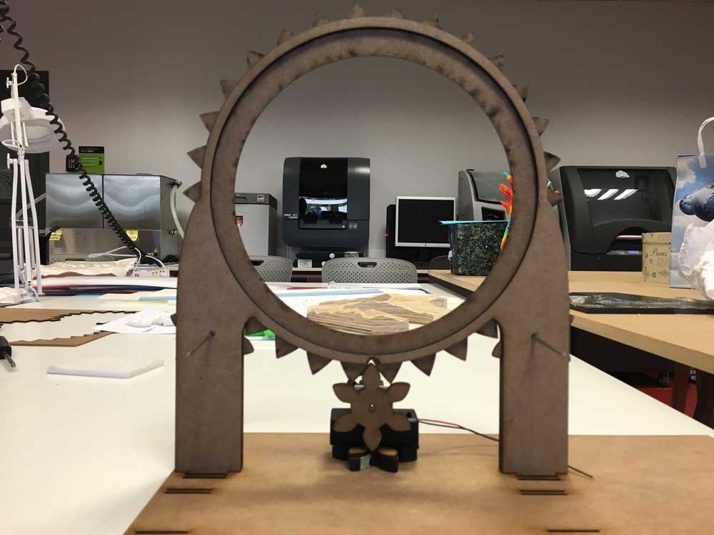
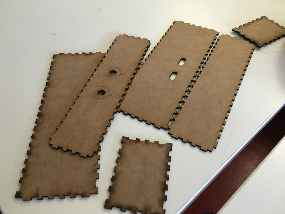
June 16, 2016Today I started laser cutting the final design:
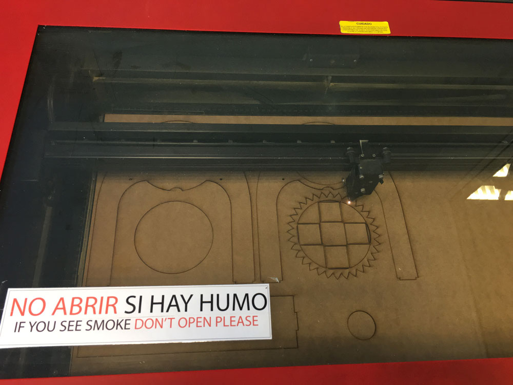
And also I tested the minimum weight for the patterns.
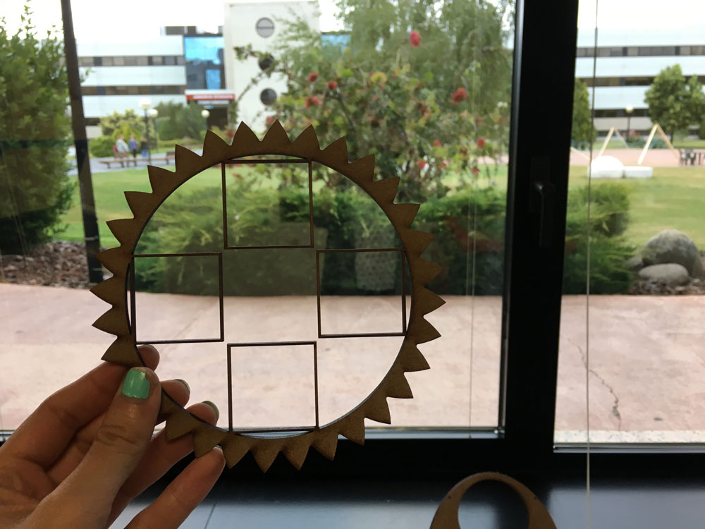
It fits smoothly and works:
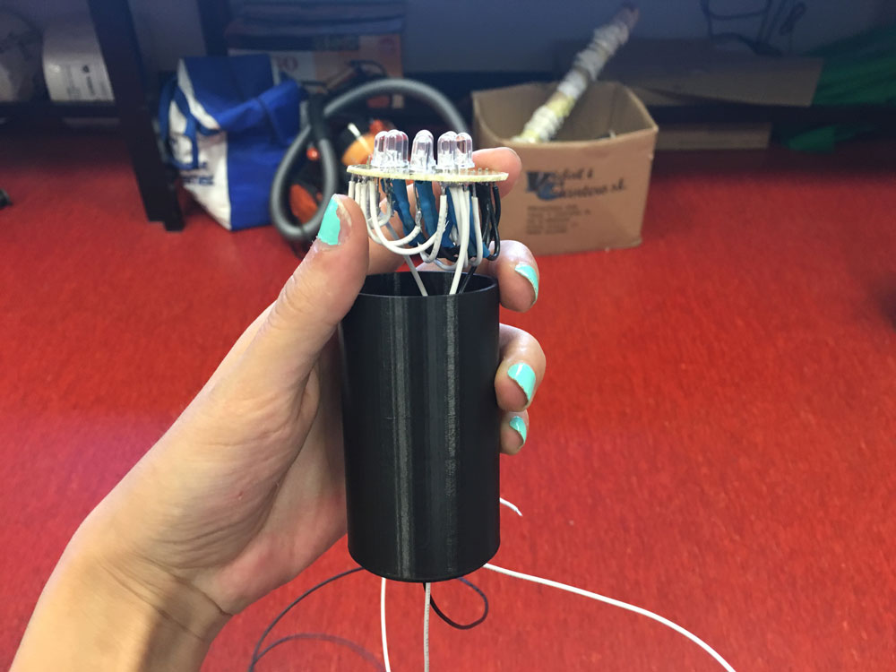
For the light source, I cutted a perfored pcb virgin board to fit into the cylinder that is going to cover the lens, and into it will fit more leds
The tube fits. I printed it in black PLA to avoid waste of lighting.
I soldered 9 leds instead of 5
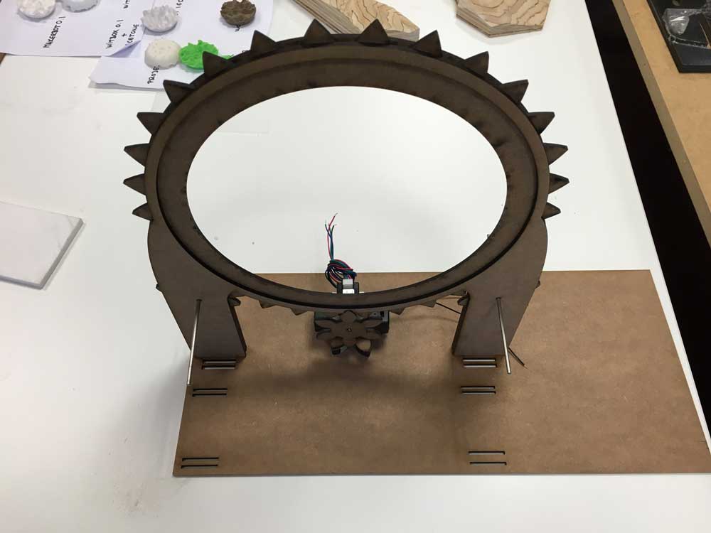
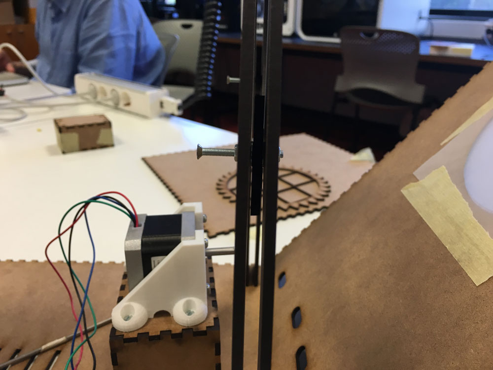
I also printed a mount for the stepper motor
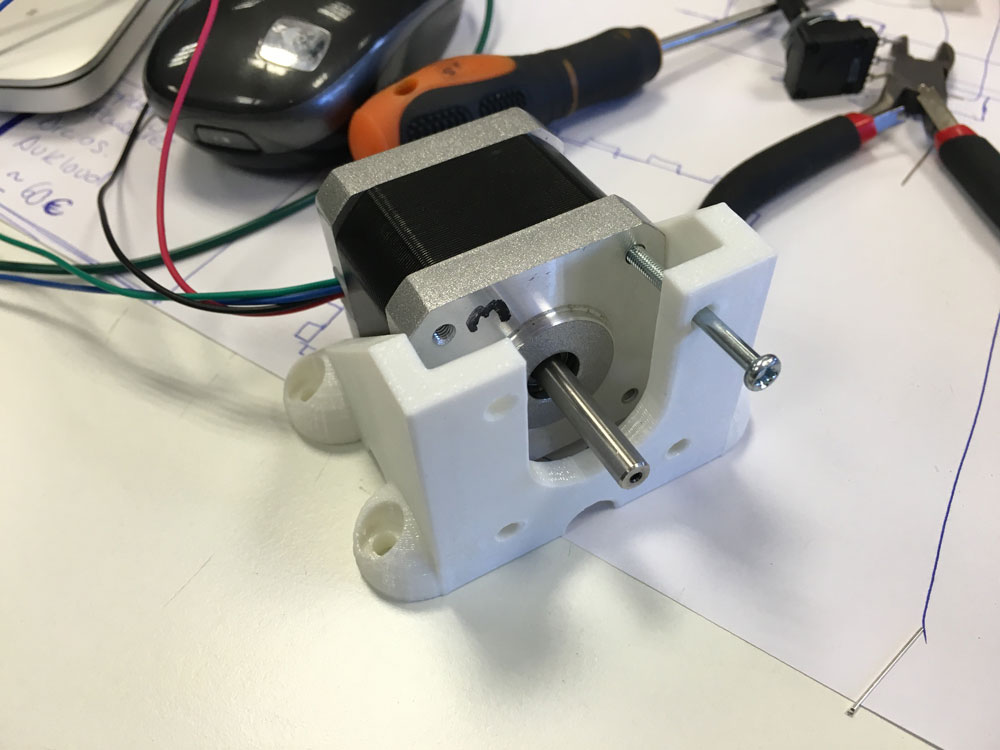
It runs smoothly! This design improved the speed and spinning.
:) :) :)
-
Final prototyping
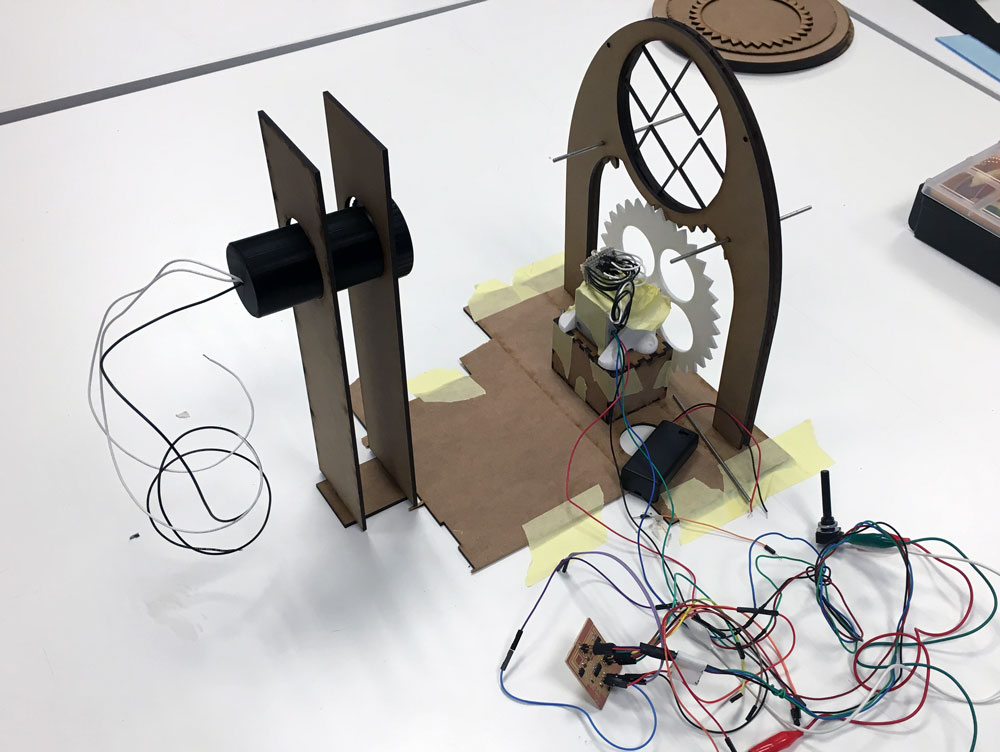
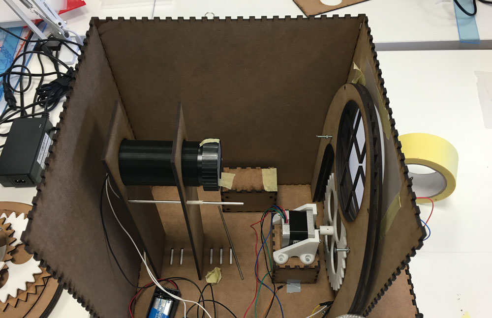
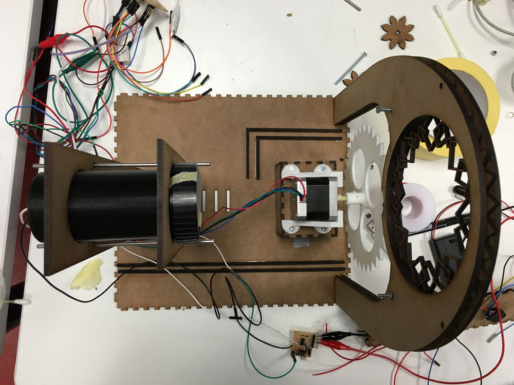
17 June, 2016Today, is the day to set everything up and running at the same time.
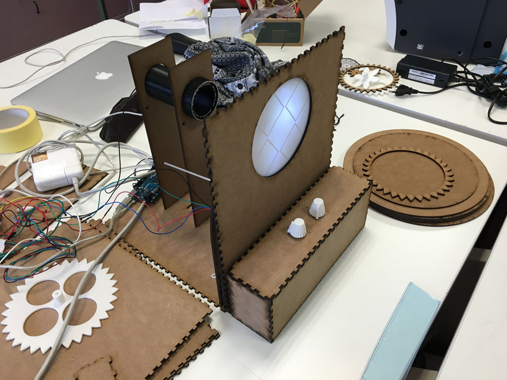
The base plattform:
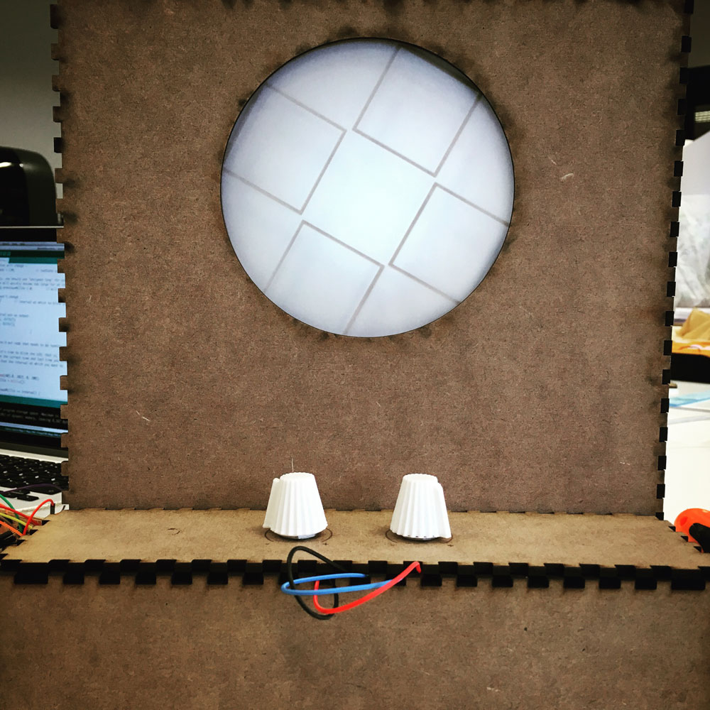
The frontal pannel with the projection surface (grease-proof paper):
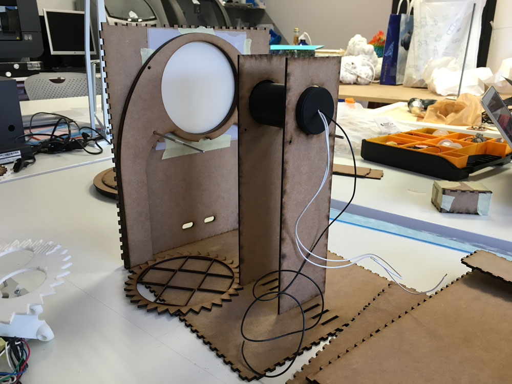
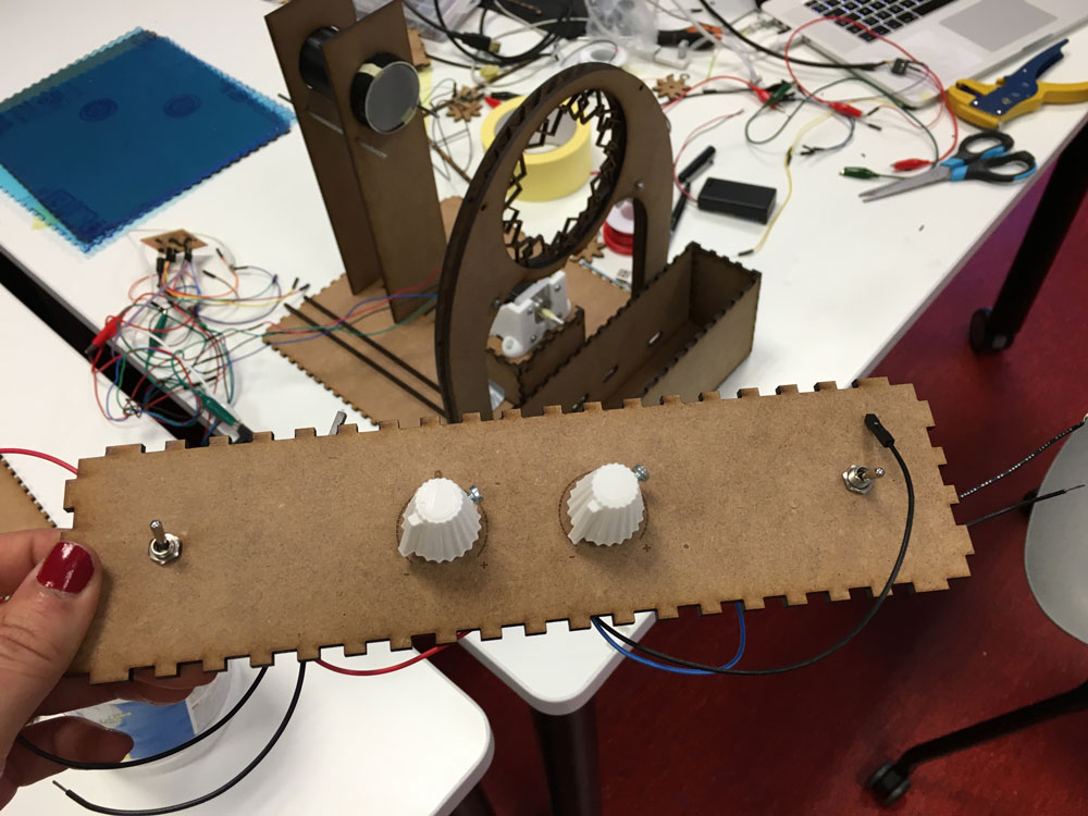
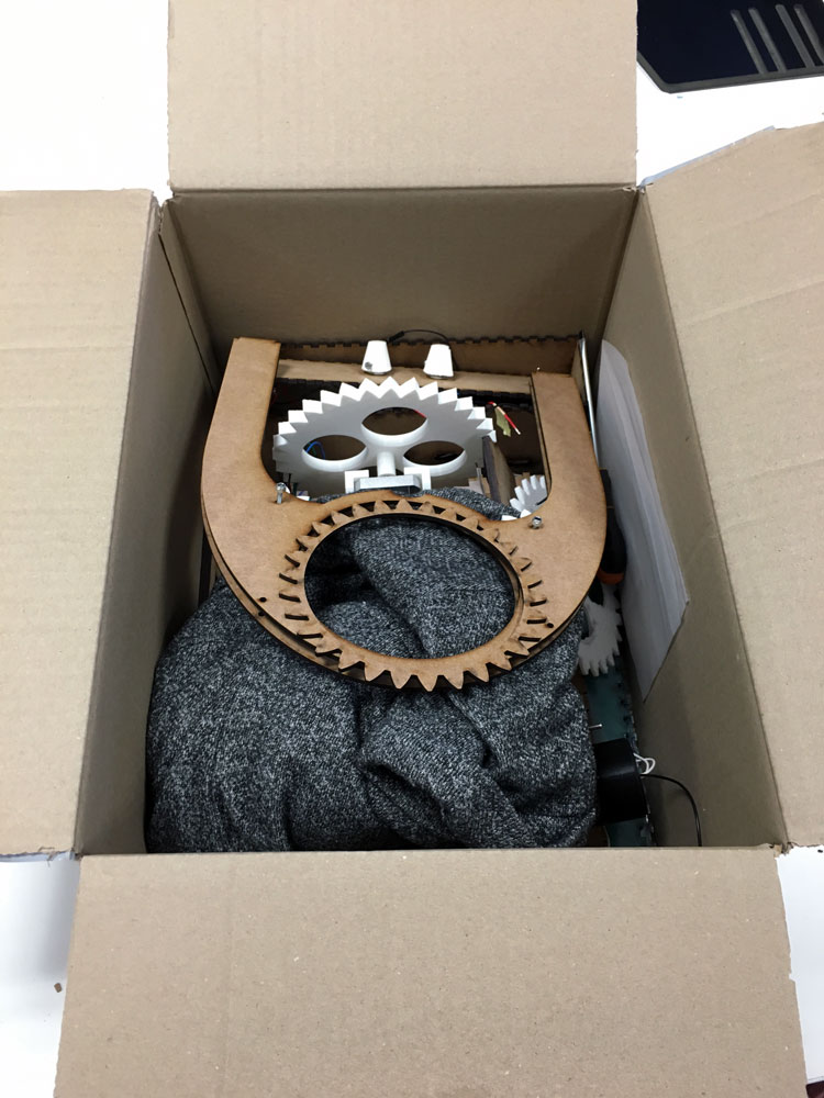
The box that will contain the electronics and the inputs (Thank you makercase):
Because these LED are so directional, I needed to diffuse the light source, with an extra layer of grease-proof paper.
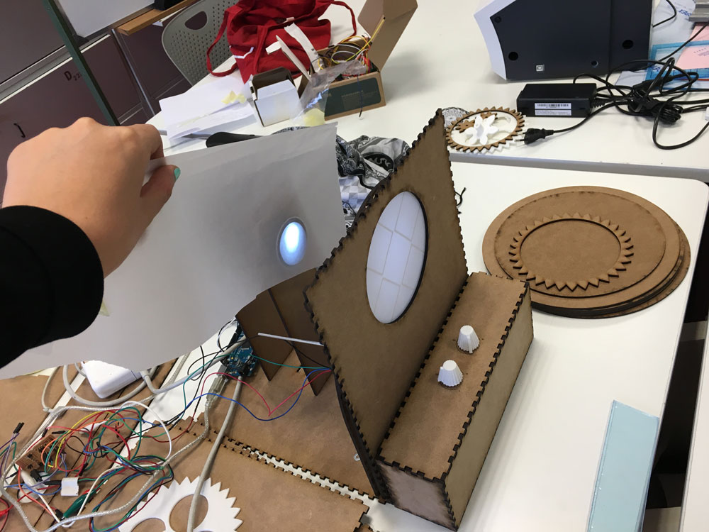
Time to screw and fit things onto their places:
I need to change these nuts, they unscrew while the motor is spinning (genius Marta). I need the blocking ones.
-
Application programming
18 June, 2016Today, I re-adapted the Processing sketch I did to the new "machine" dimensions.
I also fixed the PDF recording code, because I was using the keyboard to start recording and end it, and I I obtained a PDF with multiple repeated layers, not cool for working with them in Illustrator or send them to the laser cutter machine.
This is the code snippet I used and integrated into my code to avoid getting layer repetitions:
import processing.pdf.*; boolean record; void setup() { size(400, 400); } void draw() { if (record) { beginRecord(PDF, "####.pdf"); } // Draw something here if (record) { endRecord(); record = false; } } void mousePressed() { record = true; } -
More interface Programming
June 19, 2016Today, I continued working on the app. As for as now I only have one layer, I had to change some features.
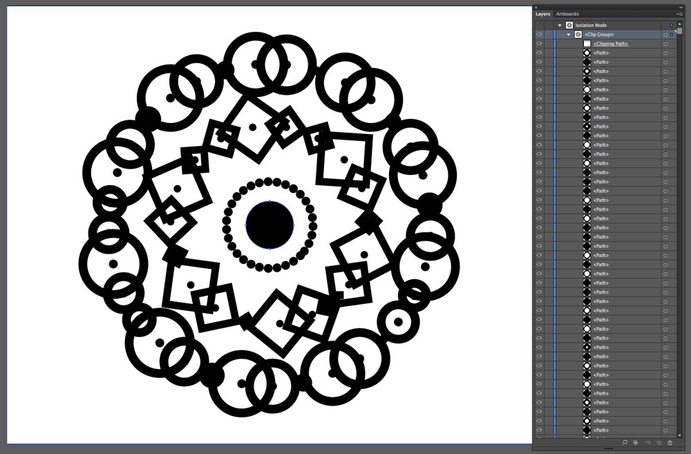
And also document the proper workflow. I can´t send the PDF file directly to the laser cutter, I need to convert the paths into outlines if I dont do that, all the frame will tear apart.
p5 recursive to laser cutter from Marta Verde on Vimeo.
Processing recursive to laser cutter 2 from Marta Verde on Vimeo.
-
Last touches
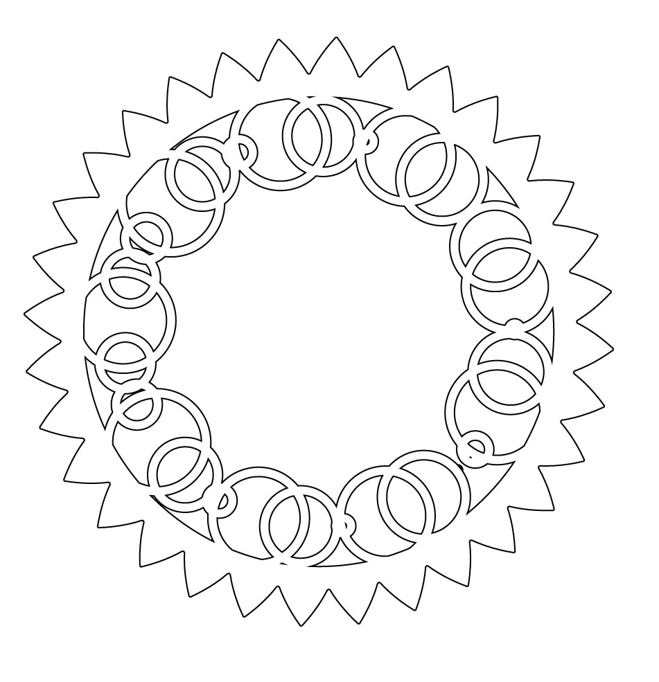
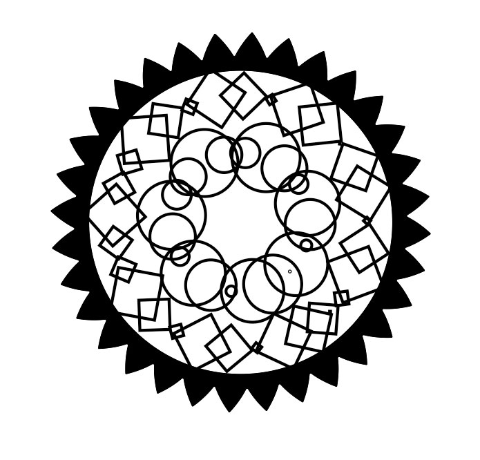
June 20, 2016Today, I laser cutted the remaining discs, made the box´s walls of methacrylate and 3d printed a wider gear for the motor, to avoid the discs to left its place.
More discs to experiment with!
The final wider gear with shaft to attach to the stepper motor:
Now it runs smoothly:
I also substituted the laser cuted plywood little support gears for 3d printed ones, 4mm height, to apport more stability:
Attaching and soldering the controllers and wires:
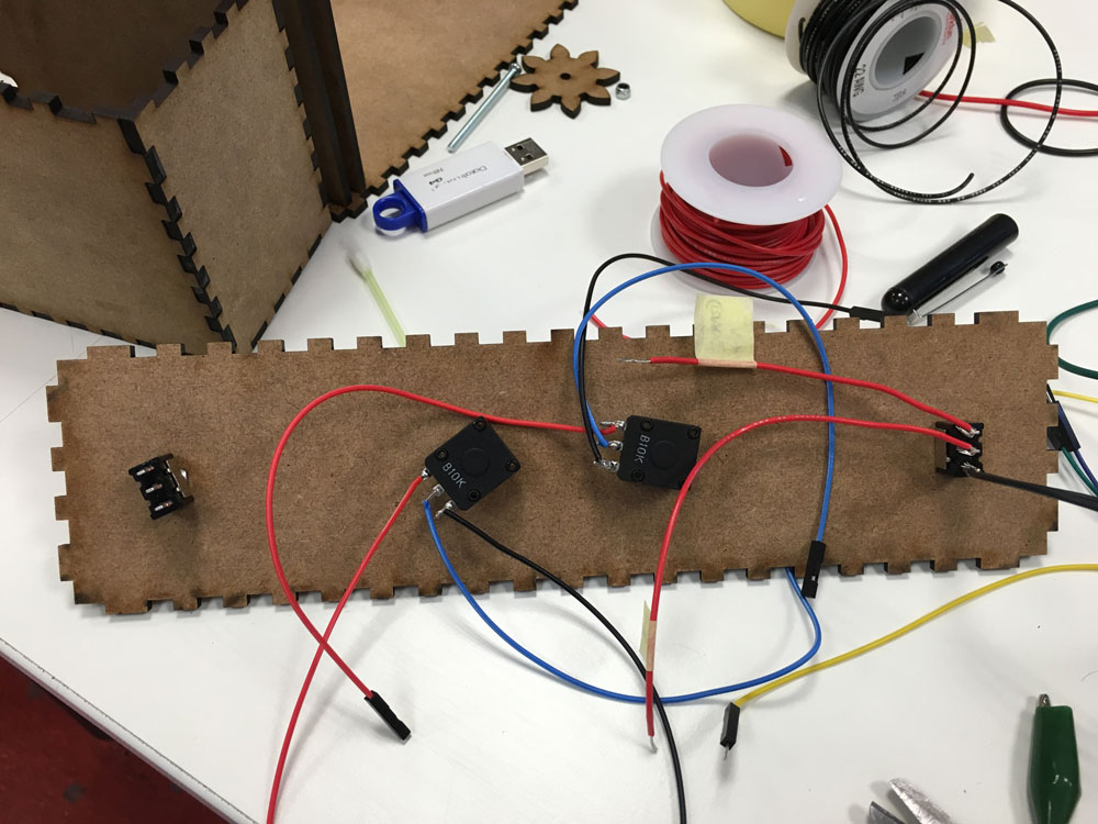
With some plywood leftovers, I made guides for holding the wires to its place:
Let´s go home!
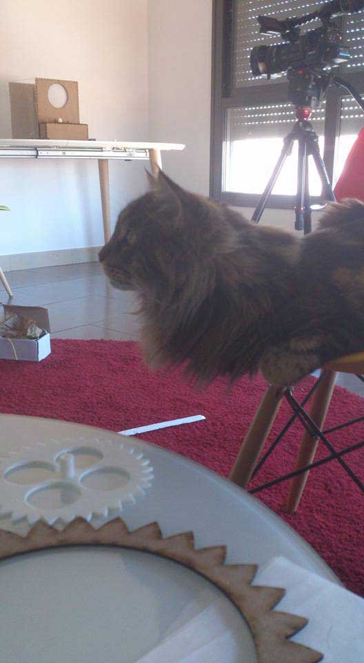
Cameras doesn´t like flickering lights
-
Video
June 21, 2016Today, is video recording time :)
-
Presentation Day
June 22, 2016Press the data "spheres" of the menu to check all the process :)
fabAcademy final project presentation from Marta Verde on Vimeo.
What tasks have been completed, and what tasks remain?
I think that I completed sucessfully a first prototype, but I need (and want) to work more on it and try to achieve the goals i had in mind when I proposed it.
What has worked?
The idea of generating an analog optical trick worked (persistence of vision).
What hasn't?
The idea of combining layers, and use the device as a "magic lantern" or projector, focus shadows is a tricky adventure.
What questions need to be resolved?
I need to learn about optics to achieve the original idea, join different shadows into one.
What will happen when?
I hope to figure it out wich game of lenses I need on the next days we have to complete assignments, and if not, for sure I will to it after If I don´t have the time. I want to continue this project.
What have you learned?
I learned a LOT. The workflow of work in a project using different techniques; the original ideas not always became true; timings, problem solving, a little bit of mechanics and structures, light behaviour....
Final project